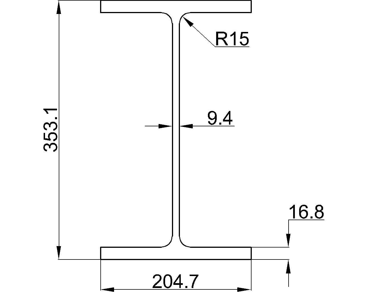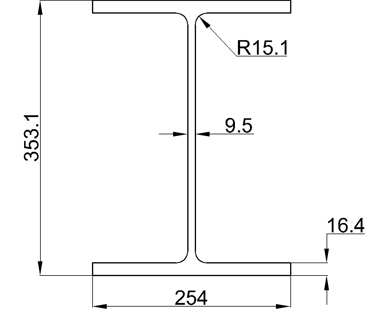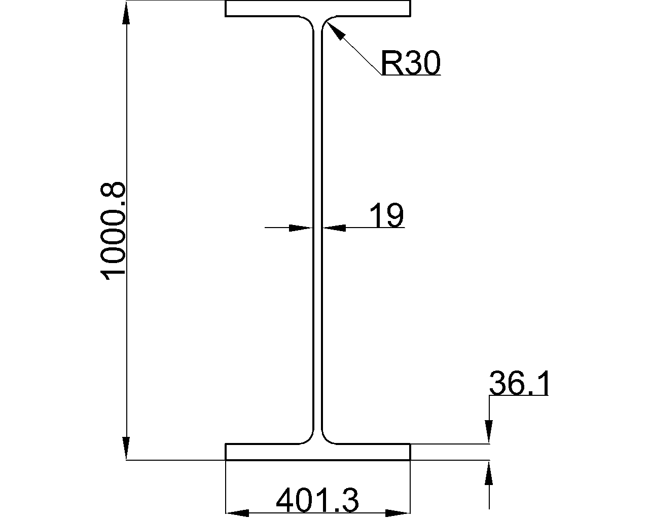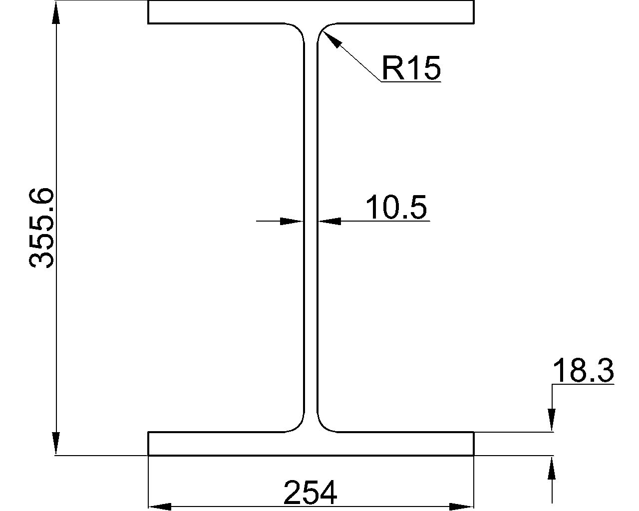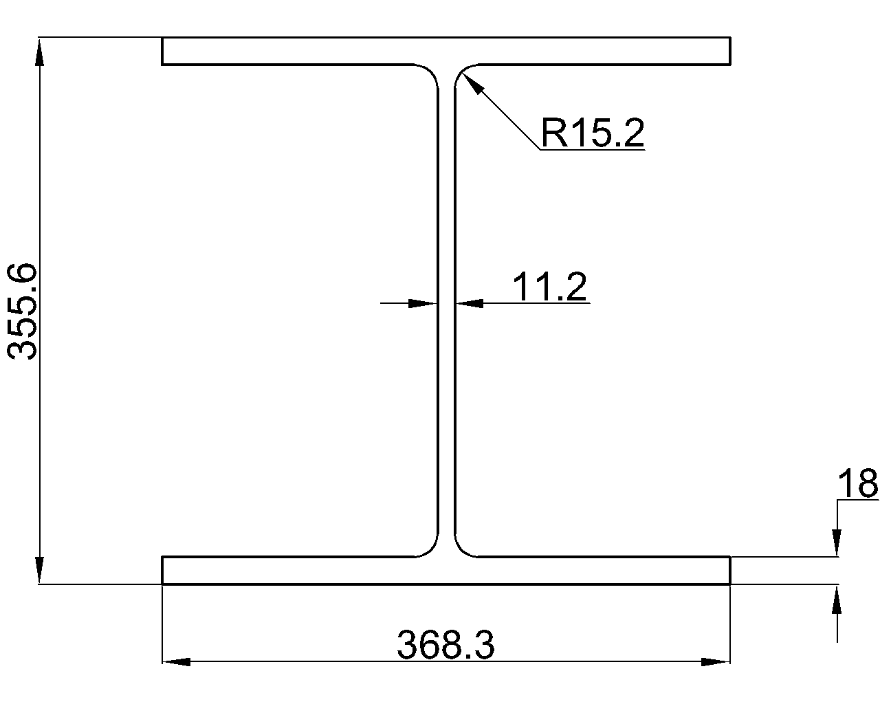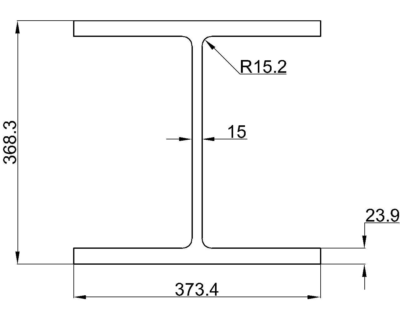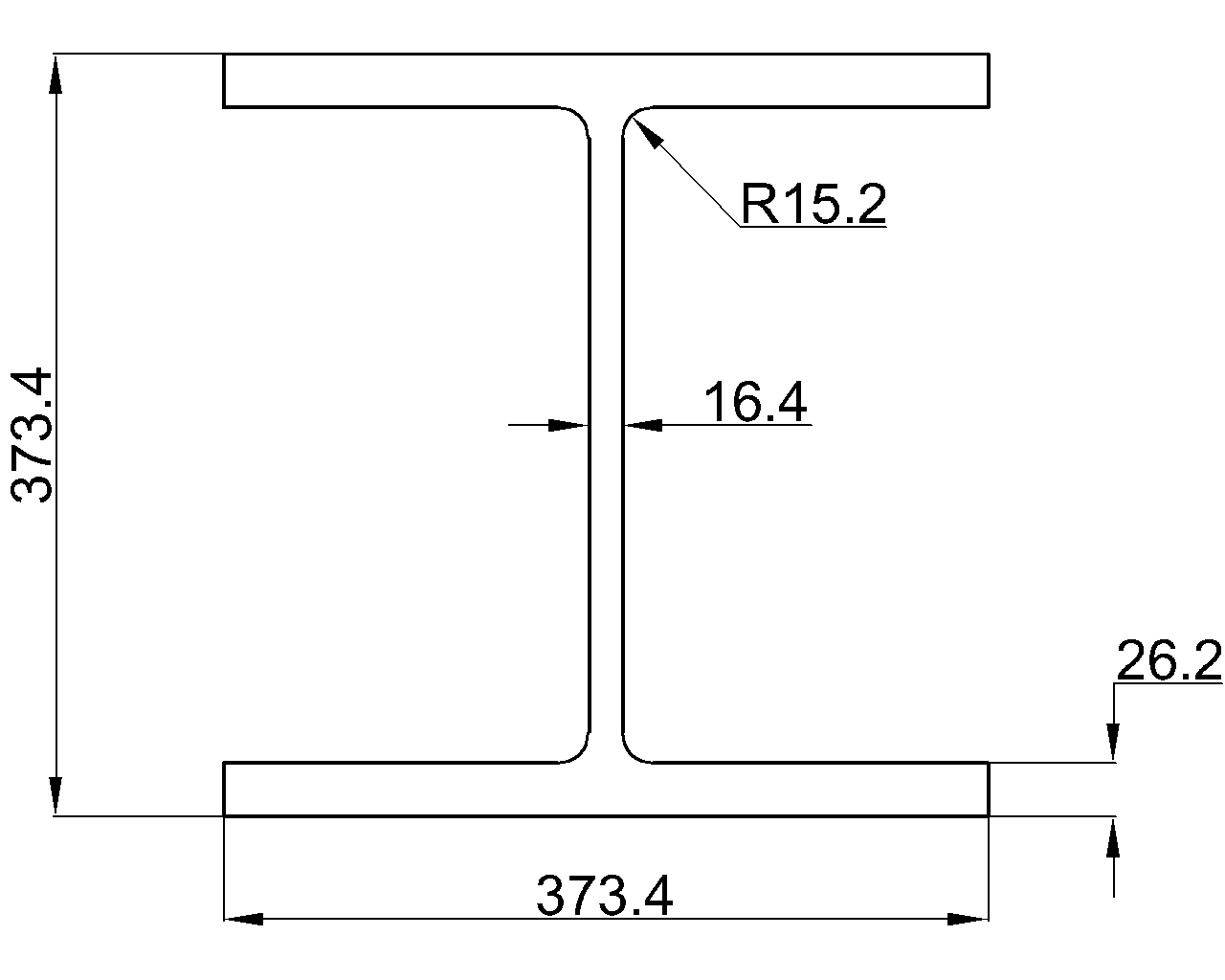
Structural steel shape tables commonly provide a published weight per unit length. That value makes it possible to estimate the weight of a beam, column, brace, channel, angle, tee, pile, or HSS member without rebuilding the section geometry in CAD. The basic multiplication is simple, but selecting the correct length and understanding what the table value includes are essential.
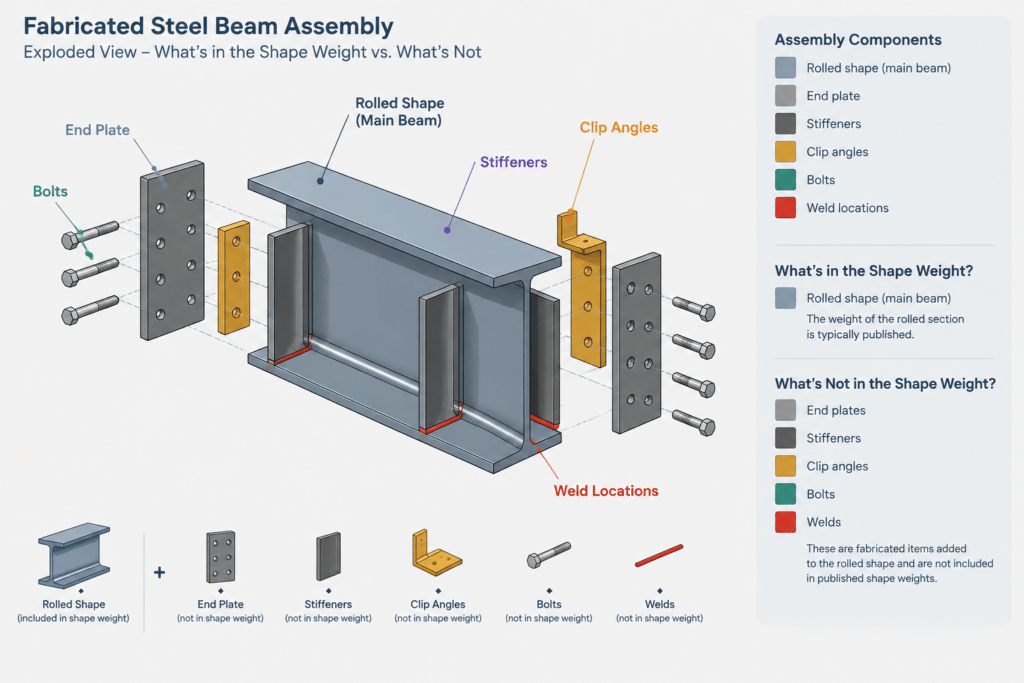
A useful takeoff should distinguish between the weight of the primary shape and the weight of the fabricated assembly. Connection plates, stiffeners, cap plates, bolts, weld metal, coatings, and other items are not automatically included in the listed weight of a rolled or hollow section.
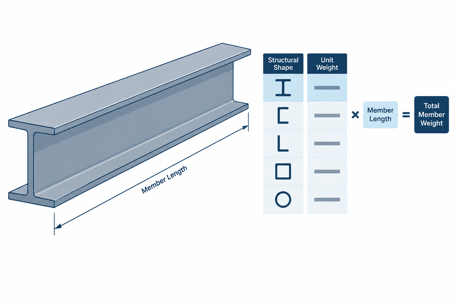
The basic member-weight calculation
For a straight member with a constant cross section, the estimated member weight is:
Member weight = published unit weight × member length
In a U.S. customary workflow, unit weight is often expressed in pounds per foot and length in feet. In a metric workflow, mass per unit length may be expressed in kilograms per meter. The units must be compatible before multiplication.
The calculation can also be rearranged for planning and checking:
- Total length = member weight ÷ unit weight
- Unit weight = member weight ÷ member length
These relationships are useful for spreadsheet checks, material summaries, and comparisons between a bill of materials and a model-derived takeoff.
Where the unit weight comes from
Use a verified shape table, project reference, or material database that identifies the exact section. Do not estimate unit weight from nominal depth alone. Two shapes with similar overall depth can have substantially different flange, web, leg, or wall dimensions.
W-shapes and related rolled sections
In a W-shape designation, the second designation value conventionally represents nominal weight per foot. Similar designation patterns are used for several other rolled-shape families. Even when the designation includes a weight value, the complete shape name should still be checked because series, depth group, and weight are all part of the identity.
Channels, angles, tees, and HP shapes
Published section data for channels, angles, structural tees, and bearing-pile shapes normally includes unit weight. For unequal-leg angles and tees, verify orientation separately from weight. Rotating or mirroring a member does not change its unit weight, but it can affect detailing, connection geometry, and the interpretation of section properties.
HSS and pipe
An HSS designation primarily communicates nominal outside dimensions and nominal wall thickness rather than member weight. Obtain unit weight from verified section data instead of interpreting one part of the designation as pounds per foot. Pipe designations follow their own naming conventions and should not be treated as interchangeable with HSS descriptions.
Choosing the correct member length
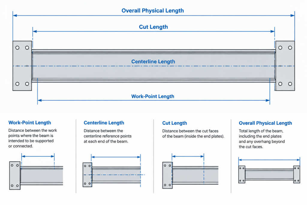
The most common takeoff error is often not the unit weight; it is the length used in the multiplication. Structural drawings and models can contain several different length concepts for the same member.
| Length reference | What it may represent | Takeoff concern |
|---|---|---|
| Work-point length | Distance between analytical or layout reference points | May extend beyond or stop short of the physical steel |
| Centerline length | Distance along the modeled member axis | Depends on model offsets and end-cut representation |
| Overall length | Extreme physical length of the member | May include projections or sloped end geometry |
| Cut length | Length used to prepare the piece for fabrication | Usually the most relevant basis for the main-shape material quantity |
| Order length | Length purchased from a supplier or cut from stock | Can include allowances and is not necessarily the finished piece length |
For a preliminary framing takeoff, a modeled centerline or work-point length may be adequate if that basis is documented. For a fabrication-oriented material list, use the defined cut length or other project-approved quantity basis. Do not silently mix length types within the same schedule.
Sloped and skewed members
A sloped brace or rafter must be measured along its actual longitudinal axis, not by its horizontal plan projection. Likewise, a member skewed in plan may be longer than a dimension measured along a building grid. A three-dimensional model can help, but only if member endpoints and offsets have been modeled consistently.
End cuts, miters, and profiles
Angled cuts can make “length” ambiguous. One flange edge may be longer than the other, while the member axis has a different modeled length. The takeoff method should identify whether weight is based on centerline cut length, maximum overall length, or stock consumed. This distinction becomes important when estimating purchasing needs rather than only finished-member weight.
Shape weight versus fabricated assembly weight
The result of unit weight multiplied by length represents the main section only. A fabricated beam or column may include many additional components.
- Shear tabs, end plates, base plates, cap plates, and splice plates
- Stiffeners, doubler plates, continuity plates, and bearing plates
- Clip angles, seats, connection tees, and small attachment shapes
- Bolts, nuts, washers, studs, anchors, and other fasteners
- Weld metal and backing components
- Galvanizing, paint, fire protection, or other applied materials
For an assembly takeoff, calculate each plate or attachment separately and add it to the main-shape estimate. Plate weight is commonly developed from material volume and an appropriate verified density or from a controlled plate-weight reference. Small components may be tracked by count or by a project-specific estimating method.
Should holes and copes be deducted?
Bolt holes, access holes, beam copes, slots, and notches remove material, but they are not always deducted in ordinary estimating workflows. Calculating every small subtraction can create considerable effort while giving a false impression of precision.
Whether deductions are included depends on the purpose of the takeoff:
- Conceptual estimate: main-shape weight is often sufficient.
- Bid or purchasing estimate: stock lengths, waste, and major removals may matter more than individual bolt holes.
- Shipping estimate: fabricated assembly weight may be required, including attachments.
- Lift planning: use a verified project-specific weight rather than an informal table calculation.
- Production tracking: the fabricator may apply established rules for additions, deductions, and remnants.
Large profile cuts or extensive openings may justify explicit deductions, but the method should be stated. A gross-shape estimate and a detailed net-material calculation are not the same quantity.
Why calculated and actual weights can differ
Published unit weights are reference values based on the defined section geometry and material assumptions used for the table. Actual manufactured products are subject to permitted dimensional and mass variation. Fabrication also changes the final assembly through cutting, drilling, welding, and attachment of other pieces.
Rounding creates another difference. If each member is rounded individually and then summed, the result may not match a total calculated from unrounded lengths. A consistent workflow is to retain adequate precision during calculations and round only the reported totals according to the project’s estimating practice.
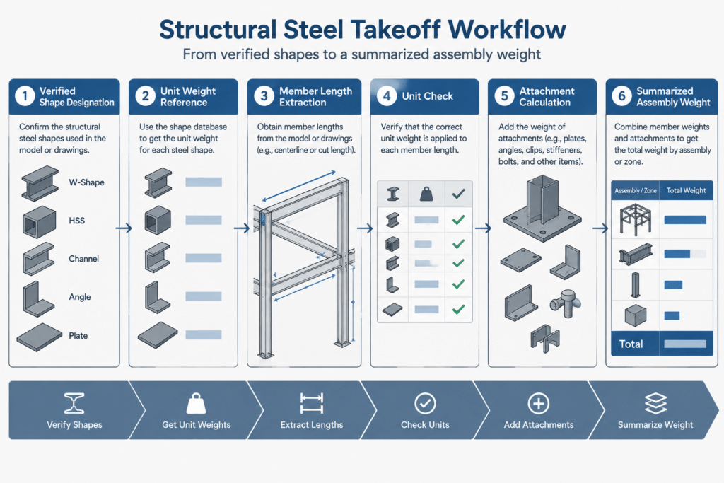
A practical takeoff workflow
- Confirm the complete shape designation. Check the section family, size, and any wall or weight component of the name.
- Obtain verified unit weight. Use the same controlled reference for all members when possible.
- Define the length basis. State whether the schedule uses work-point, model-axis, overall, cut, or order length.
- Check units. Convert length before multiplying if the unit-weight and length units do not match.
- Calculate main-shape weight. Multiply unit weight by the applicable length.
- Add attachments separately. Track plates, secondary shapes, and hardware using an appropriate method.
- Apply deductions consistently. Avoid selectively subtracting holes or cuts without a documented rule.
- Group and reconcile. Summarize by piece mark, shape, sequence, shipping unit, or another useful category.
- Perform a reasonableness check. Compare total length, member count, and average weight against the framing shown.
Using CAD and BIM quantities carefully
CAD polylines, block attributes, and model objects can automate length extraction, but automation does not establish that the underlying geometry is correct. Confirm insertion points, scale, units, end offsets, and whether the object represents the actual steel envelope or only a symbolic centerline.
Duplicate members, hidden objects, reference files, and alternate design options can also inflate a quantity report. Before relying on an export, compare model counts with plans, elevations, framing schedules, and piece marks. A reliable steel takeoff combines verified section data with a clearly defined geometric basis; neither the table nor the model is sufficient by itself.