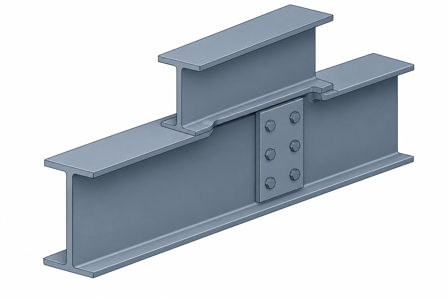
A beam cope is a localized removal of material from a member flange and part of its web. Copes are commonly used where a supported beam must fit around the flange of a supporting beam, girder, or other framing element while leaving room for the connection. Although the finished cut may appear simple, beam cope detailing requires coordination among member geometry, connection components, erection clearances, fabrication methods, and structural design.
The detailer’s task is not merely to draw a notch. The cope must describe the intended cut unambiguously without assuming that nominal shape depth, flange thickness, or rolled fillet geometry is identical for every member. Its dimensions should also correspond to the work point and elevation system used throughout the project.
What a Beam Cope Does
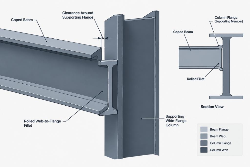
At a typical framed beam connection, the end of the supported beam approaches the web of a supporting member. If the supported beam’s top flange conflicts with the supporting member’s top flange, a portion of the supported flange and web may be removed. This creates space for the members to intersect at the required elevations.
The remaining web can then receive the specified connection, such as a plate, angle, or other engineered attachment. The cope itself does not define the connection’s capacity. Cope geometry and the reduced section at the beam end must be reviewed as part of the connection design.
Common Cope Configurations
| Configuration | Material removed | Typical coordination issue |
|---|---|---|
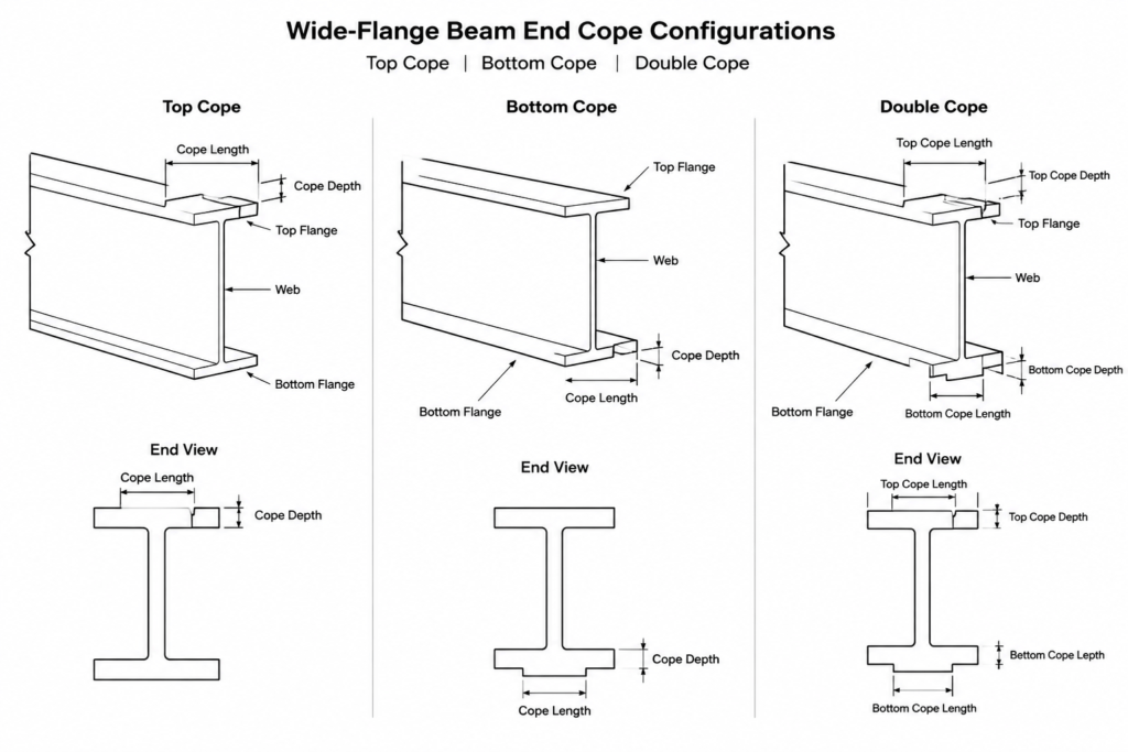
| Top cope | Top flange and adjacent web at the member end | Clearance below the supporting member’s top flange |
| Bottom cope | Bottom flange and adjacent web at the member end | Clearance above a lower flange, seat, or obstruction |
| Double cope | Both flanges and portions of the web | Available web depth for the connection and the stability of the remaining end region |
| Skewed cope | A cope adapted to a non-square framing intersection | True geometry may not be visible in a standard orthographic view |
A top cope is frequently encountered when beams share a common top-of-steel elevation. The supported beam must pass below the supporting flange while maintaining the intended elevation. Bottom and double copes arise when framing geometry or connection components create additional interference.
These descriptions identify geometric arrangements, not standard cuts. The actual cope must be established for the specific members and connection.
The Main Dimensions of a Cope
Cope length
Cope length is the horizontal extent of the cut measured from the member end or another clearly identified reference. It must provide room for the supporting flange, rolled fillet region, connection components, permitted fabrication variation, and required erection clearance.
A detail should make clear whether the stated length applies to the flange removal, the straight web cut, or another geometric feature. Ambiguous dimensioning can cause a fabricator to interpret the same value differently from the connection model.
Cope depth
Cope depth is the vertical distance from a defined edge or surface to the horizontal cut line. On a top cope, it may be referenced from the top of the beam; on a bottom cope, from the bottom. When elevations are critical, the detailer should confirm how this local dimension relates to top-of-steel, bottom-of-steel, and member work lines.
The depth is influenced by actual supporting-member geometry. Relying only on a nominal depth contained in a shape designation can miss flange-thickness and fillet-region conflicts.
Cope corner and transition
The intersection between the horizontal and vertical cuts should not be represented as an unexplained sharp internal corner. Fabrication may use a rounded transition, drilled termination, or another approved cutting method. The required treatment should be coordinated with the project’s connection design and fabrication practice.
A CAD arc drawn for appearance is not automatically a valid cope radius. If the transition geometry is design-sensitive, it must be explicitly defined or referenced to verified project requirements.
Geometry That Must Be Checked
A reliable cope detail considers more than the visible outline of two nominal sections. Relevant geometry can include:
- The supporting member’s flange width and thickness
- The supporting web location and rolled web-to-flange fillet
- The supported beam’s flange thickness and web thickness
- Any end setback between the beam and supporting web
- Connection plates, angles, welds, bolts, and access requirements
- Skew, slope, camber, or rotation of either member
- Top-of-steel and bottom-of-steel elevations
- Fabrication and erection clearances specified for the project
- Coatings or other project-specific conditions that affect fit-up
Rolled fillets deserve particular attention. A supporting beam is not a collection of perfectly square plates. Its web transitions into each flange through a curved region. Extending the supported beam too close to that region can produce an interference even when simplified rectangular CAD outlines appear to fit.
Cope Dimensions Versus End Setback
Cope length and beam end setback are related but are not interchangeable. End setback locates the end of the supported member relative to the supporting member or work point. Cope length describes how far the flange removal extends from that end.
For example, increasing the end setback may move the entire beam away from the support, while increasing the cope length removes more material without changing the beam-end location. Confusing these controls can affect connection placement, bolt locations, weld access, and the remaining beam web.
Both values should be tied to consistent references. In a model or drawing set, avoid mixing dimensions from a supporting-member centerline, supporting-web face, and supported-beam end unless each relationship is clearly shown.
How to Show a Beam Cope on Shop Drawings
An effective shop detail normally includes an elevation or web view where the cut profile is visible. A section, plan, or auxiliary view may be needed for skewed framing or unusual flange cuts.
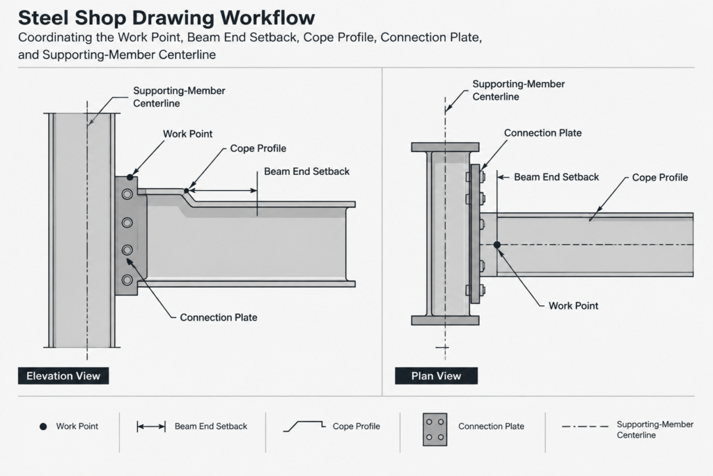
The drawing should communicate:
- Which end and which flange are coped
- The cope length and depth
- The corner or cut termination where required
- The beam-end setback and connection reference
- The relationship between the cope and connection components
- Whether the opposite side is identical, mirrored, or different
- Any special fabrication instruction that has been verified for the project
Use directional descriptions carefully. Labels such as left, right, near side, and far side depend on the view. End marks, orientation views, piece marks, and consistent viewing conventions are more reliable than isolated notes.
CAD and Model-Based Detailing Workflow
- Place the members from verified work points and elevations. Establish framing geometry before creating local cuts.
- Use the correct section geometry. Confirm the selected shapes and relevant dimensions against the project reference.
- Apply the beam-end setback. Do not use the cope to conceal an incorrect member-end location.
- Model the supporting flange and fillet region. A simplified rectangle may be acceptable for some views, but interference checks should account for realistic geometry.
- Add the connection components. The available web area and access cannot be evaluated from the members alone.
- Create the cope from controlled dimensions. Avoid freehand trimming or geometry that cannot be traced to a detail dimension.
- Review multiple views. Check elevation, plan, section, and three-dimensional views, especially for skewed or sloped framing.
- Compare the drawing with the model. Ensure displayed dimensions describe the same cut that will be fabricated.
Automated clash detection can identify overlapping solids, but it cannot determine whether a cope is structurally acceptable, easy to fabricate, or properly dimensioned. It should support—not replace—technical review.
Common Beam Cope Detailing Errors
- Using nominal depth as exact geometry: A shape designation alone does not establish every flange, web, and fillet dimension needed for fit-up.
- Ignoring rolled fillets: Square-corner CAD profiles can conceal interference near the supporting web.
- Oversizing the cope for convenience: Additional clearance also removes additional material and may affect the engineered connection.
- Leaving the inside corner undefined: A generic sharp corner can conflict with fabrication practice or design intent.
- Dimensioning from inconsistent references: Mixing work-line, member-end, and face-of-web dimensions can produce cumulative errors.
- Checking only one view: Skew and slope can make a cut appear adequate in elevation while it interferes in plan or true projection.
- Assuming mirrored ends: Opposite ends may frame into different support sizes or connection arrangements.
Final Review Checklist
Before releasing a coped beam detail, verify that the member sizes, elevations, orientation, setback, and connection arrangement match the latest project information. Confirm that the cope clears the actual supporting geometry rather than only a schematic outline. Check that the remaining web and corner treatment agree with the engineered connection requirements and that the cut can be understood from the issued views and dimensions.
A well-detailed cope is precise rather than merely generous. It provides the required fit while preserving the geometry assumed by the connection design and giving the shop an unambiguous, traceable cutting profile.