Structural steel drawings do more than describe geometry. They establish how a fabricator will locate holes, cut members, place plates, and verify finished work. The dimensioning method therefore affects not only drawing clarity but also how variation can accumulate across a part or assembly.
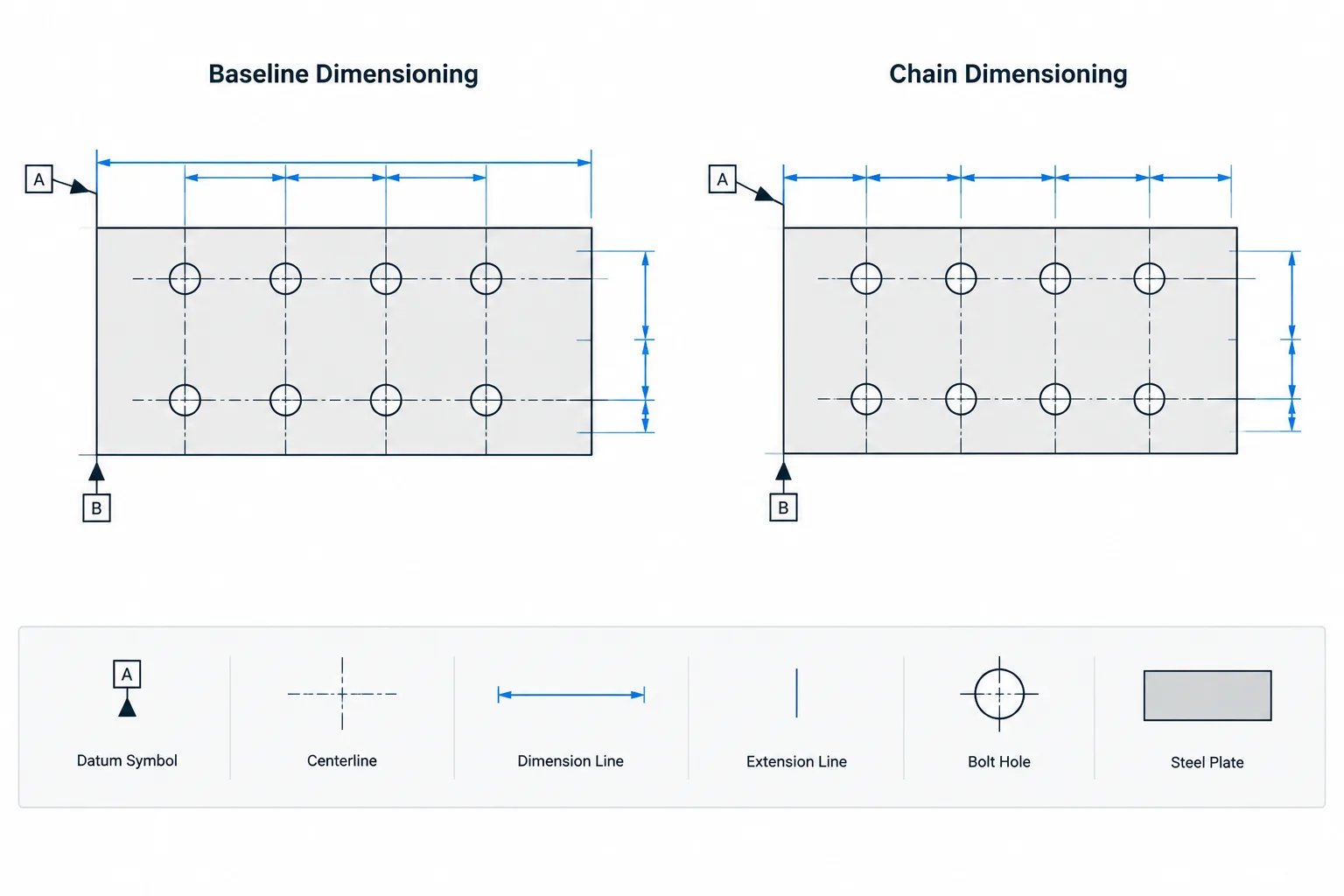
Baseline dimensioning locates multiple features from a common datum. Chain dimensioning locates each feature from the one before it. Both methods can be valid, but they communicate different layout logic. Choosing between them requires an understanding of functional relationships, fabrication workflow, inspection, and the consequences of accumulated error.
What Is Baseline Dimensioning?
Baseline dimensioning measures several features from one shared reference. On a beam, that reference might be the member end, a work point, a column line, or the centerline of a connection. On a plate, it may be a finished edge, a centerline, or another clearly identified datum.
For example, a series of bolt-hole centerlines can each be located from the left end of a plate. The individual dimensions do not depend on the actual position of the preceding hole. Each hole is tied directly to the same controlling reference.
Baseline dimensions are especially useful when:
- Every feature must align with geometry elsewhere in the structure.
- A member end or work point controls the connection location.
- Accumulated variation across a hole pattern must be limited.
- Inspection will be performed from a common reference.
- Intermediate features may be revised without shifting the remaining layout.
A baseline must be recognizable and physically useful. An ambiguous edge, an unmarked work point, or a theoretical point that cannot be established during fabrication may weaken an otherwise sound dimensioning scheme.
What Is Chain Dimensioning?
Chain dimensioning places dimensions consecutively from one feature to the next. A hole is located from the previous hole, a stiffener from the previous stiffener, or one plate edge from an adjacent break point.
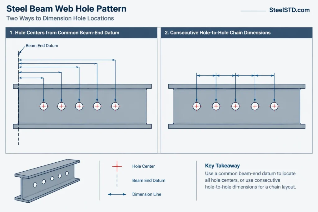
This method clearly communicates local spacing. It is often appropriate when the relationship between neighboring features is more important than their independent positions relative to an end datum. Equal spacing in a repetitive pattern is a common example.
The primary concern is accumulation. Each completed interval may vary slightly from its intended location. When multiple intervals are placed in sequence, the final feature can reflect the combined effect of the preceding intervals. The issue is not that chain dimensions are inherently incorrect; it is that they assign control differently from baseline dimensions.
Comparing the Two Methods
| Consideration | Baseline dimensioning | Chain dimensioning |
|---|---|---|
| Reference | Common datum for multiple features | Previous feature in the sequence |
| Primary strength | Controls absolute feature locations | Communicates local spacing clearly |
| Accumulated variation | Does not build through the dimension chain in the same way | Can accumulate across consecutive intervals |
| Revision behavior | One feature may move without redefining every later interval | A changed interval may affect downstream locations |
| Typical steel use | Connection locations, end setbacks, critical hole lines | Repeated spacing, local plate geometry, secondary patterns |
| Inspection approach | Measure repeatedly from the datum | Measure successive feature-to-feature distances |
Running and Coordinate Dimensions
Running dimensions are a compact form of baseline dimensioning. Instead of drawing a separate dimension line from the datum to every feature, a series of cumulative values is shown along one dimension line or adjacent to successive features. Every displayed location still originates from the same zero point.
Coordinate dimensioning uses labeled positions referenced to established axes or datums. It can be effective for base plates, complex gusset plates, equipment-support frames, and irregular hole patterns. Coordinates may reduce overlapping dimension strings, but the drawing must make the origin, axis directions, and referenced feature centers unmistakable.
Running or coordinate dimensions should not be mistaken for chain dimensions merely because the values appear in a sequence. The key question is where each value begins: at the common datum or at the preceding feature.
Applying Dimensioning Methods to Steel Members
Beam connection holes
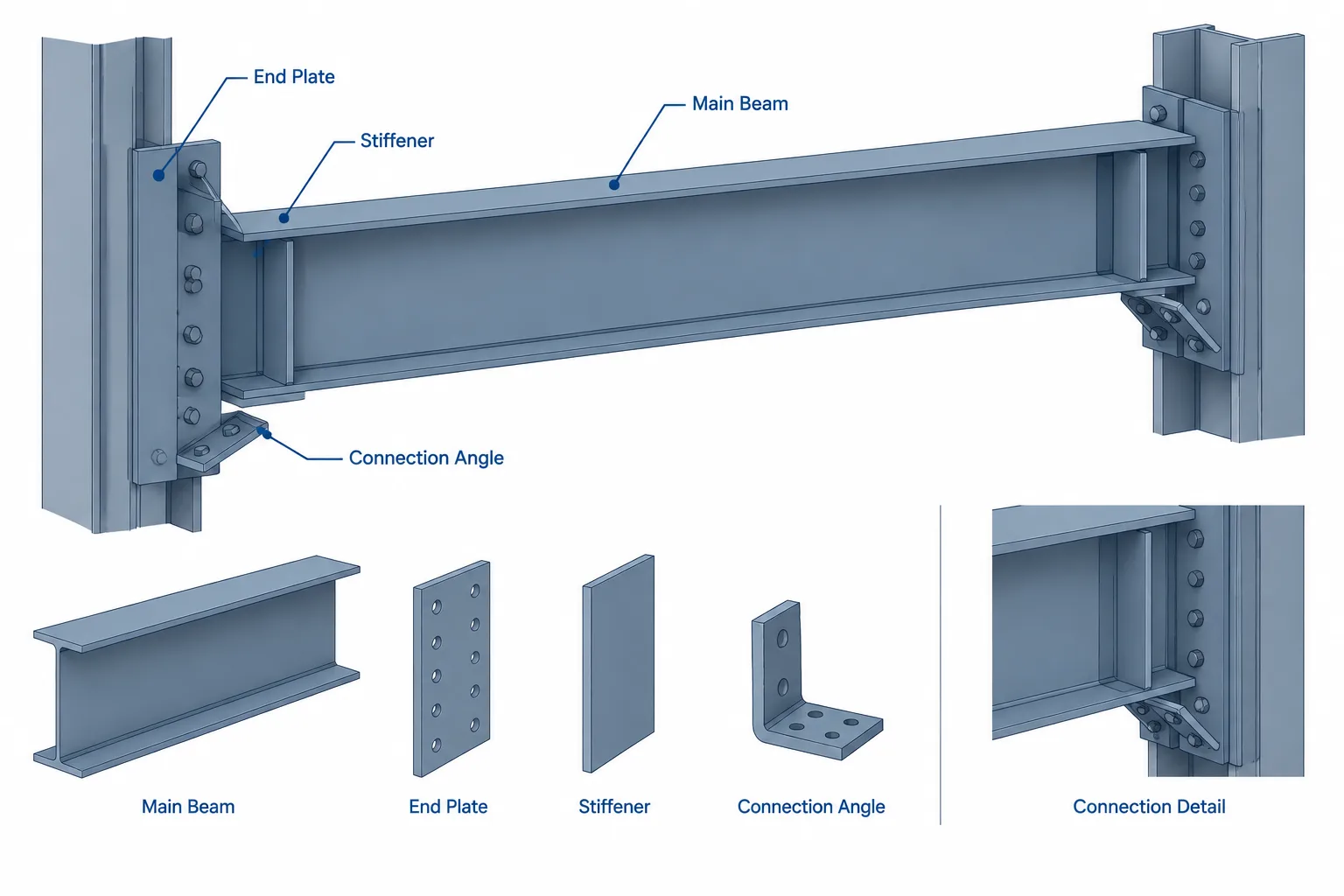
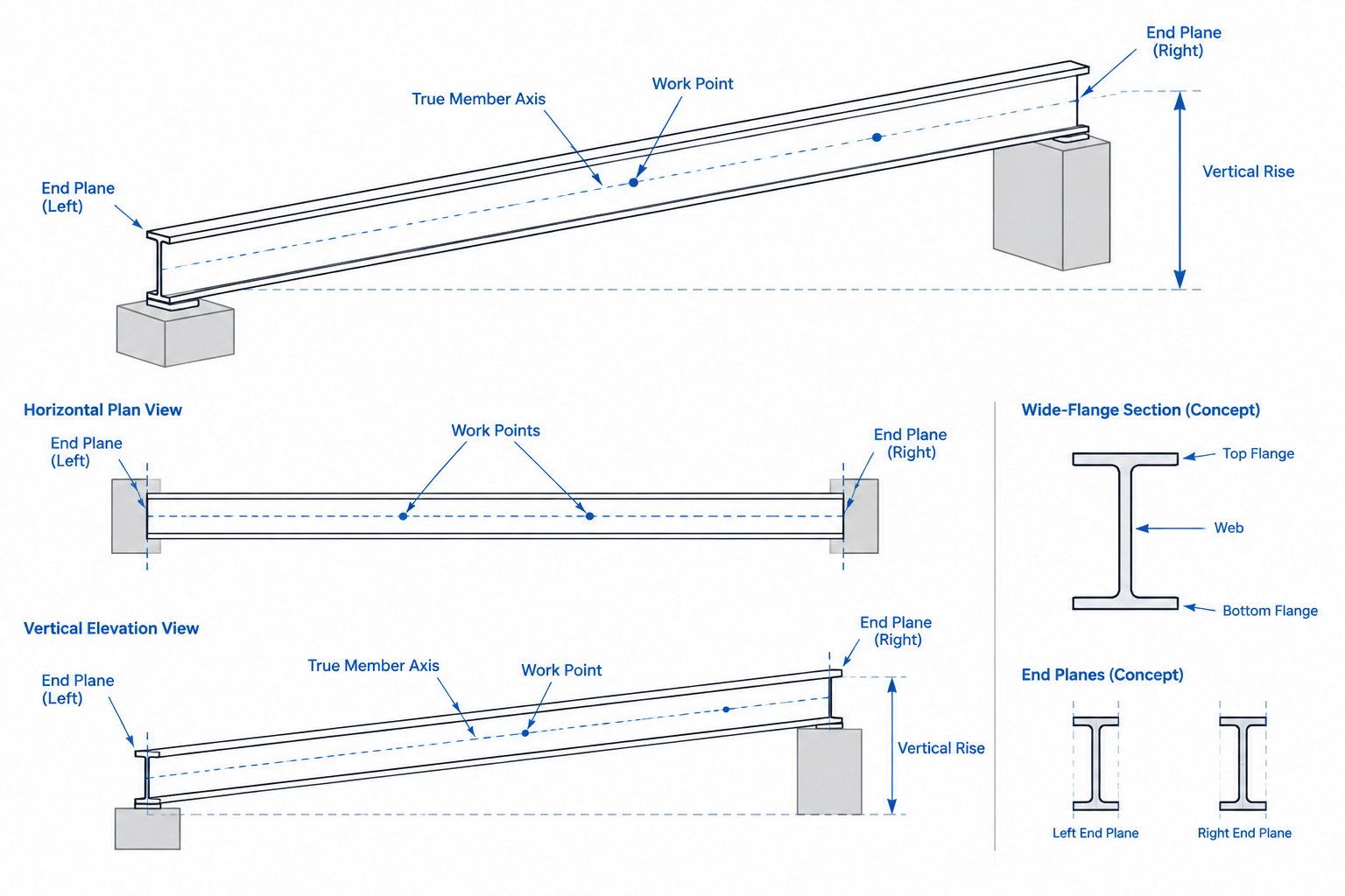
Beam-end hole patterns are commonly controlled by the relationship between the member end, connection work point, supporting member, and connecting material. Locating the pattern from a meaningful end datum or connection centerline can prevent an unrelated intermediate feature from influencing its position.
Within the pattern, local bolt spacing may be shown as a chain or as repeated spacing when that presentation is clear. This creates a useful hybrid: the pattern has an absolute location, while its internal geometry is described locally.
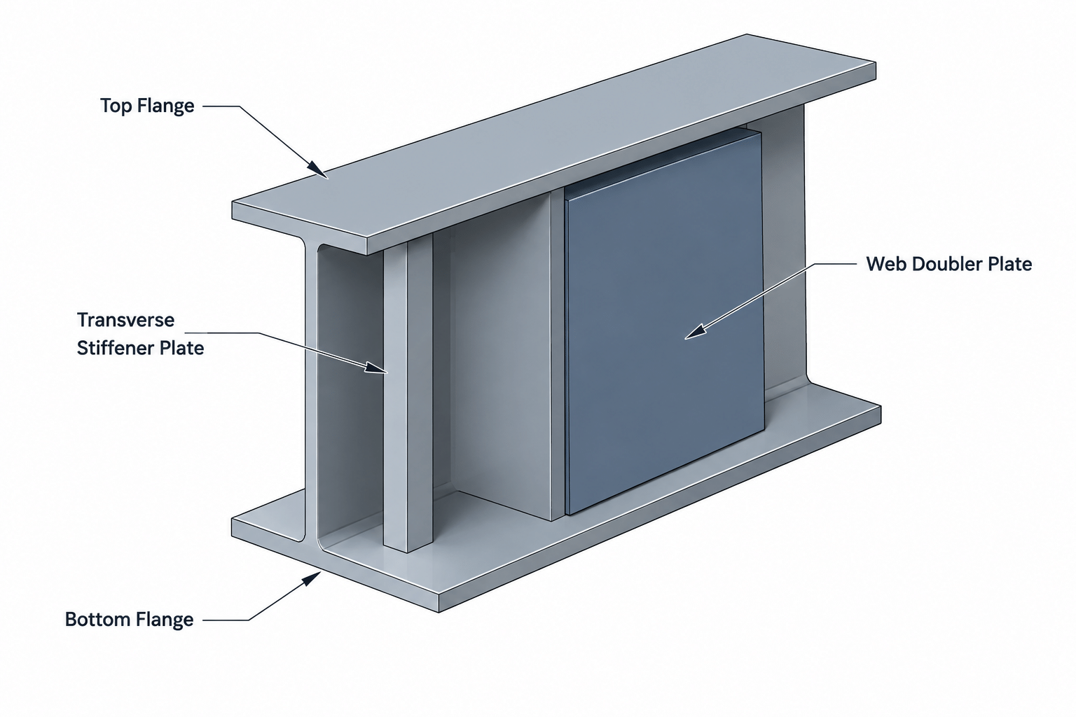
Stiffeners and connection plates
A stiffener intended to align with another member, concentrated reaction, or external plate should be dimensioned from the reference that governs that alignment. Dimensioning it only from a nearby clip, hole, or secondary plate can hide the actual design relationship.
For regularly spaced intermediate stiffeners, a combination of overall limits and repeated spacing may be more readable than a large group of overlapping baseline dimensions. The detail should still identify which end or centerline controls the pattern.
Base plates and anchor-rod holes
Base plate layouts often benefit from centerlines and coordinate-style dimensions because the hole pattern must relate to the supported column and the field-established anchor-rod layout. Plate edges alone may not be the most reliable controlling references, particularly when edge dimensions are secondary to member and anchor alignment.
The drawing should distinguish the column centerlines, plate centerlines, hole centers, and any intentional offset between them. A symmetric-looking detail must not be relied upon to imply symmetry.
Gusset plates and irregular profiles
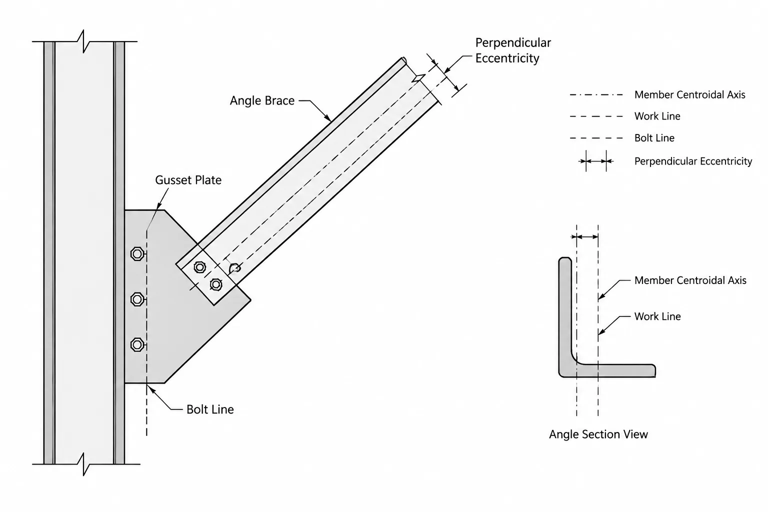
Irregular gusset geometry may require several reference types. Bolt groups may be located from work lines, while plate boundaries are defined by edge offsets, intersections, radii, or cut-line endpoints. Trying to force the entire plate into one long dimension chain can obscure the structural relationships.
A practical approach is to establish primary datums first, locate critical holes and connection lines from them, and then define the surrounding plate profile. This separates connection geometry from the excess material needed to form the plate boundary.
Overall Dimensions Do Not Replace Feature Locations
An overall dimension is valuable as a fabrication and checking reference, but it does not necessarily define the intermediate geometry. Conversely, a complete chain of intermediate dimensions may leave the overall size unclear.
Where appropriate, drawings can show both:
- Controlling dimensions needed to lay out the part.
- Overall dimensions useful for cutting, fit-up, and verification.
- Reference dimensions that confirm geometry without controlling fabrication.
Reference dimensions should be visually identified according to the project drafting convention. Duplicate controlling dimensions should be avoided because separate dimension strings can become inconsistent after a revision.
Select Datums That Match Fabrication and Function
A good datum is stable, identifiable, and connected to the function of the part. Common candidates include member ends, finished plate edges, centerlines, work points, and established grid references. Rolled-shape flange toes, curved fillet boundaries, rough thermal-cut surfaces, and theoretical intersections that are difficult to establish may be poor shop datums unless the fabrication process specifically supports them.
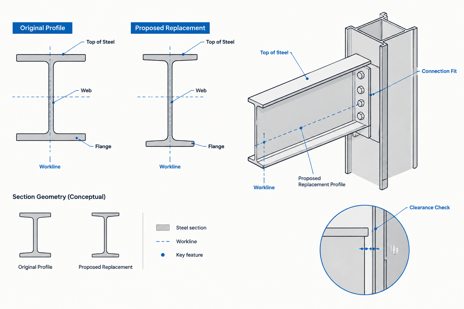
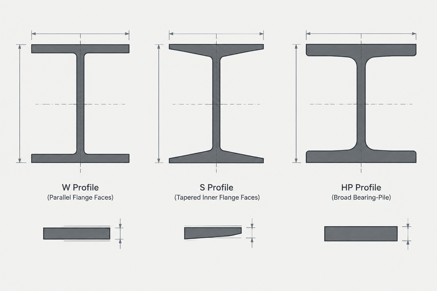
The best geometric datum is not always the best functional datum. A dimension may be easy to draw from the end of a W-shape, but the connection may actually be controlled by a column grid line or beam work point. The detail should communicate both when the distinction matters.
A CAD Workflow for Reviewing Dimension Logic
CAD makes it easy to place dimensions, but associativity and precision do not determine whether the chosen references are appropriate. Before issuing a drawing, review the dimensional structure rather than only the displayed values.
- Identify controlling geometry. Mark member ends, work points, centerlines, and connection interfaces.
- Classify features. Separate critical connection features from secondary cuts, clips, and repeated items.
- Choose the primary datum. Use the reference that controls fit, alignment, or field location.
- Locate critical features. Dimension important hole groups, plates, and stiffeners directly from the appropriate datum.
- Describe local patterns. Add spacing, gage, and repeated-layout information without creating contradictory dimensions.
- Add useful overall checks. Show overall length or pattern extent where it helps fabrication and inspection.
- Test revisions. Consider what happens if one intermediate feature moves. Unrelated downstream geometry should not shift unintentionally.
- Remove redundancy. Retain one clear controlling route for each location.
Common Dimensioning Problems
- Closed dimension loops: Every segment and the overall distance are shown as controlling, leaving no clear location for allowable variation to be absorbed.
- Mixed datums without explanation: Some features originate at the member end while others originate at a grid or work point, but the relationship between those references is missing.
- Dimensions to hidden or unclear geometry: The shop cannot easily identify the referenced feature in the view provided.
- Repeated dimensions in multiple views: A revision updates one view but leaves a conflicting value elsewhere.
- Reliance on drawing scale: An undimensioned feature is expected to be measured graphically rather than defined.
- Assumed symmetry: Similar-looking holes or edges are treated as centered without an explicit centerline or equal-spacing instruction.
Use a Hybrid Strategy Deliberately
Most effective steel details do not use baseline or chain dimensioning exclusively. They use each method according to the relationship being communicated. A connection group can be located from a work point, its bolt rows described by local spacing, and its overall extent shown as a check. A plate can be positioned from the member centerline while its edge profile is defined from nearby cut intersections.
The goal is not to maximize the number of dimensions. It is to create an unambiguous path from the project reference system to the fabricated feature. Final drawings must also follow the governing contract documents, project standards, fabrication practices, and responsible design requirements.