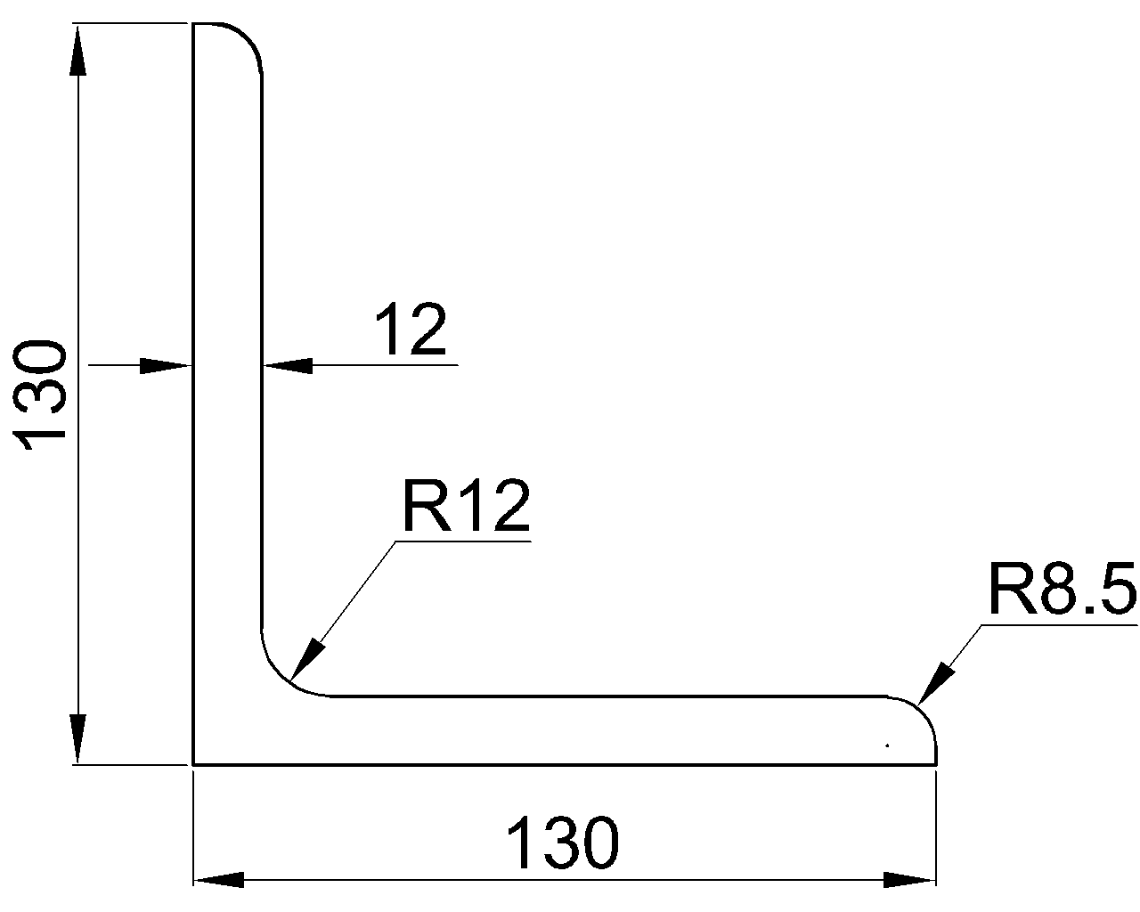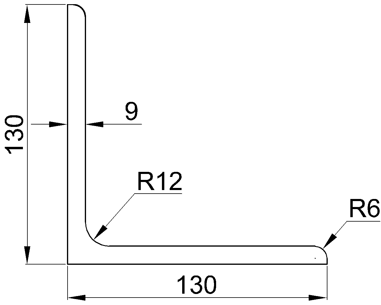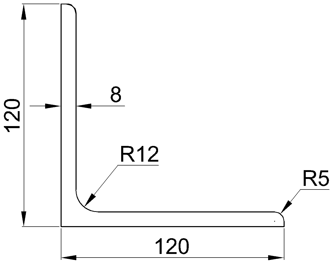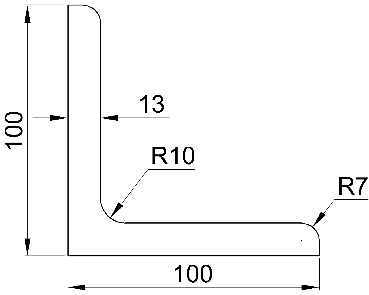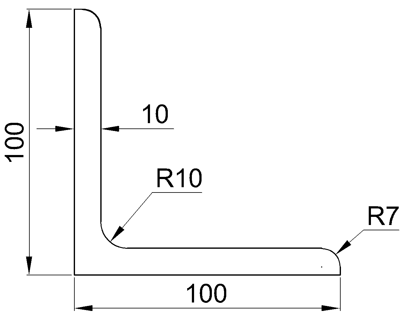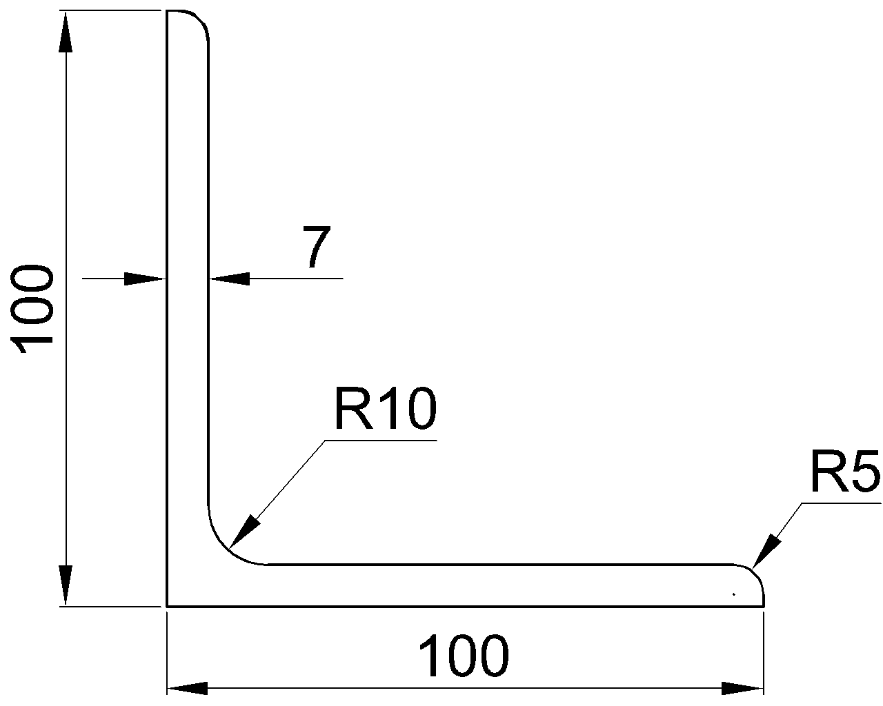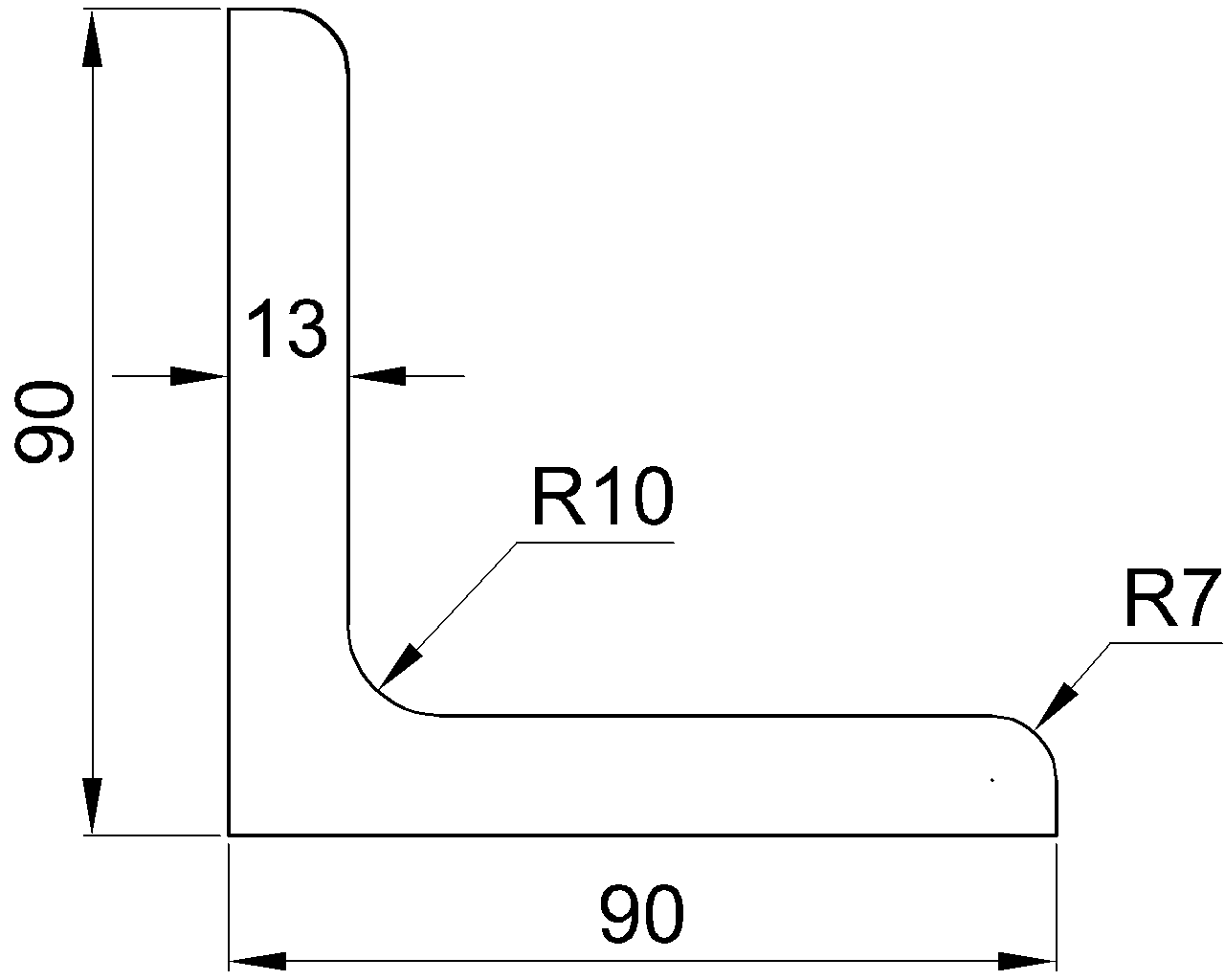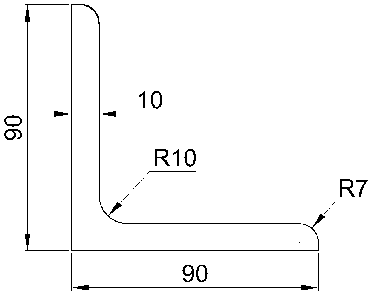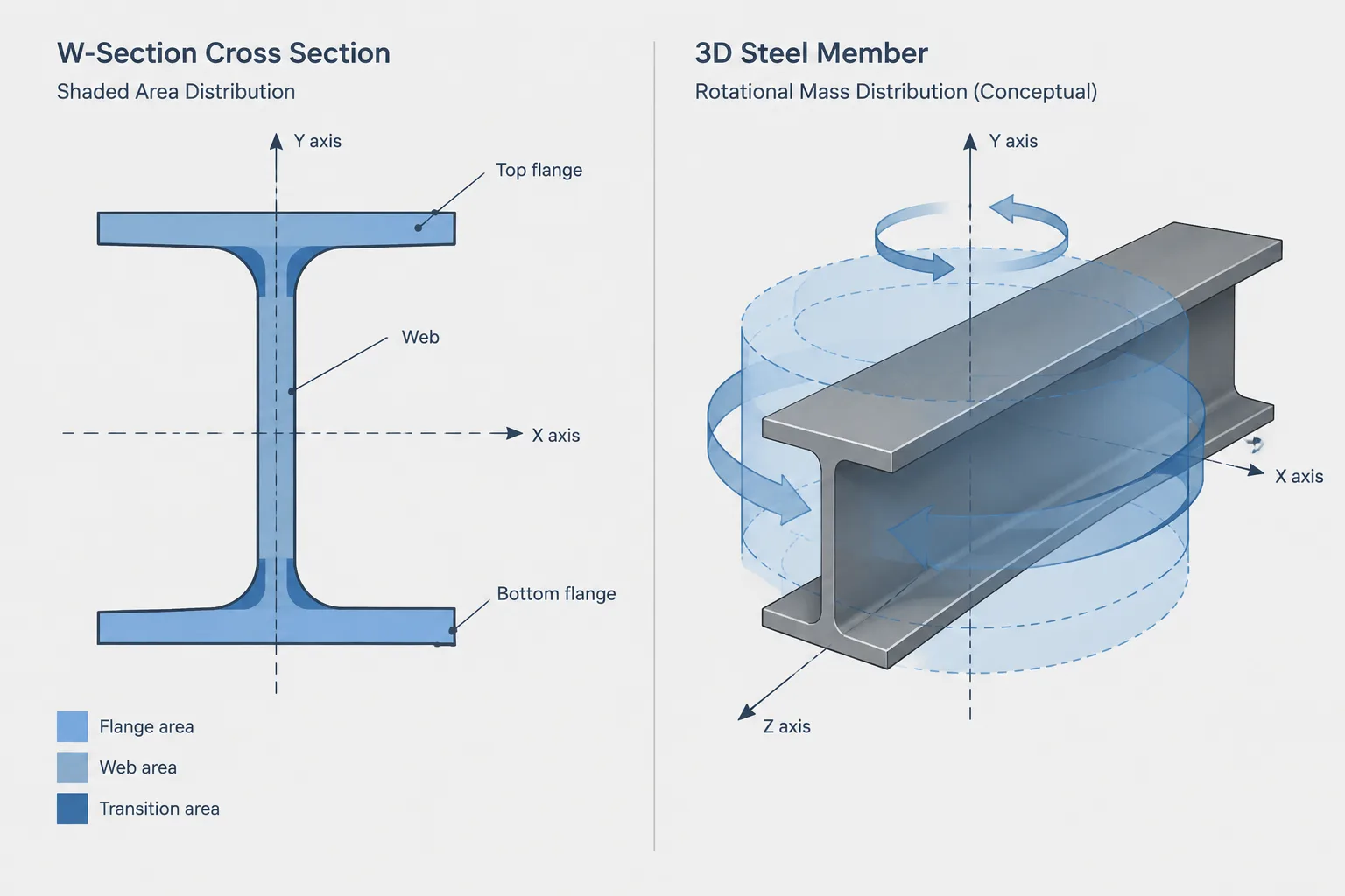
The phrase moment of inertia can refer to two different properties. Structural steel shape tables normally report the area moment of inertia, also called the second moment of area. Mechanical and dynamic analyses may instead use the mass moment of inertia. Both are often labeled with the letter I, but they describe different physical behavior and cannot be substituted for one another.
This distinction matters when transferring steel geometry among shape databases, CAD drawings, structural analysis models, and mechanical simulation software. The property name, reference axis, and units must all agree before a value is used.
What Is the Area Moment of Inertia?
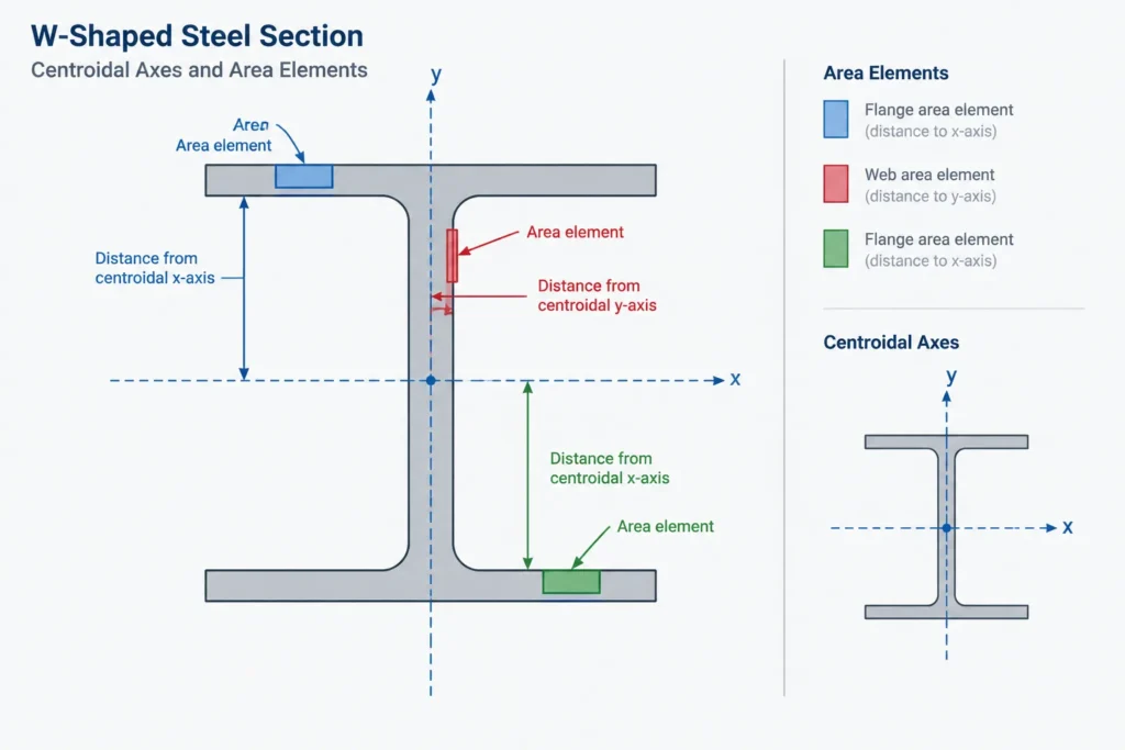
The area moment of inertia describes how a cross-sectional area is distributed relative to a selected axis. For a steel shape, it depends on section geometry rather than member length, steel density, or total member mass.
For an axis designated x, the property can be expressed conceptually as:
Ix = ∫ y² dA
Each small element of cross-sectional area contributes according to the square of its distance from the axis. Material farther from the axis has a much greater effect than material close to it. This is why the placement of flanges can strongly influence the bending properties of a W-shape even when the web contains a meaningful portion of the total area.
Area moment of inertia is typically reported in length raised to the fourth power, such as in.4 or mm4. The fourth-power unit is an immediate clue that the value is a section property rather than a mass property.
Where area moment of inertia is used
- Elastic bending and deflection calculations
- Column and member stability relationships
- Derivation of elastic section modulus
- Calculation of radius of gyration
- Comparison of strong-axis and weak-axis stiffness
- Section-property checks for rolled and built-up shapes
Area moment of inertia does not by itself represent load capacity. Strength and serviceability checks also depend on material properties, member length, bracing, boundary conditions, load application, local geometry, and the applicable design requirements.
What Is the Mass Moment of Inertia?
Mass moment of inertia describes how mass is distributed relative to an axis of rotation. It represents rotational inertia: the resistance of a physical object to angular acceleration about that axis.
For an axis of rotation, it can be expressed conceptually as:
Imass = ∫ r² dm
Here, the integration is performed over mass rather than cross-sectional area. The distance r is measured from each mass element to the applicable rotational axis.
Mass moment of inertia has units combining mass and length squared. Depending on the unit system and software environment, the displayed units may take several forms. Unlike an area property, it depends on the density, full three-dimensional geometry, member length, and location of the rotational axis.
Where mass moment of inertia is used
- Rigid-body rotational dynamics
- Mechanical motion and acceleration studies
- Equipment, machinery, and moving-assembly simulations
- Some vibration and dynamic system models
- CAD mass-property reports for three-dimensional solids
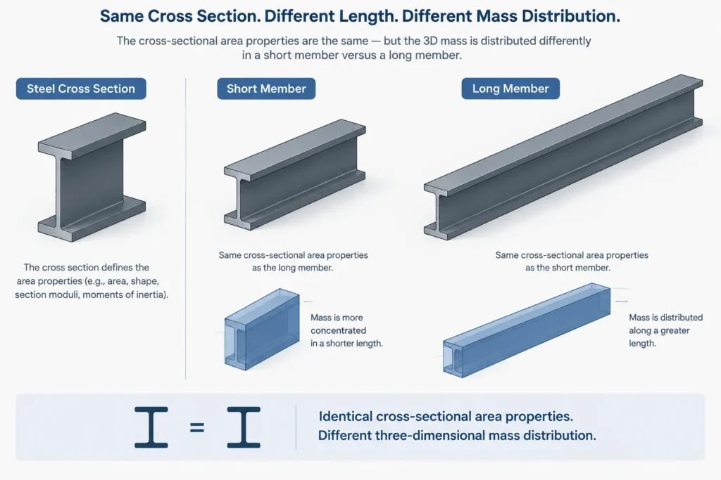
A steel beam section extruded into a short solid and the same section extruded into a long solid have the same cross-sectional area moment of inertia. They do not have the same mass moment of inertia because their total mass and three-dimensional mass distribution differ.
Side-by-Side Comparison
| Characteristic | Area moment of inertia | Mass moment of inertia |
|---|---|---|
| Describes | Distribution of cross-sectional area | Distribution of mass |
| Common symbol | I | I, Imass, or a software-specific label |
| Typical dimensional form | Length4 | Mass × length2 |
| Depends on material density | No | Yes |
| Depends on member length | No, for a defined cross section | Yes, for a three-dimensional member |
| Typical source | Steel shape table or section-property calculation | Three-dimensional solid model or dynamics calculation |
| Primary use | Bending, deflection, stability, and section comparison | Rotational motion and dynamic response |
How Area Moment of Inertia Relates to Other Steel Section Properties
Several familiar properties in structural steel tables are derived from the area moment of inertia. Recognizing these relationships helps confirm that the correct type of inertia is being used.
Elastic section modulus
The elastic section modulus about a selected axis is related to the area moment of inertia by:
S = I / c
The distance c is measured from the neutral axis to the relevant extreme fiber. For an unsymmetric section, the distances to opposite extreme fibers can differ, producing different section modulus values on the two sides.
Radius of gyration
The radius of gyration of a cross section is:
r = √(I / A)
This is a geometric section property. Despite its name, it is not the same as the radius used to describe the rotational mass distribution of a complete three-dimensional object.
Product of inertia
The product of inertia describes the distribution of area relative to two reference axes. It is important for unsymmetric sections and transformations to principal axes. It remains an area property and commonly has length-to-the-fourth units.
Do Not Confuse Either Property with the Torsional Constant
The symbol J can create another source of confusion. In some mathematical contexts, a polar area moment may be identified as J. In structural steel tables, however, J commonly identifies the Saint-Venant torsional constant.
For general structural shapes—especially open sections such as W-shapes, channels, angles, and tees—the torsional constant should not be assumed to equal a simple polar sum of two bending moments of inertia. Bending stiffness, uniform torsional response, warping behavior, and rotational mass response are separate concepts. Always identify the complete property name rather than relying on a single letter.
Why CAD Property Reports Can Be Misread
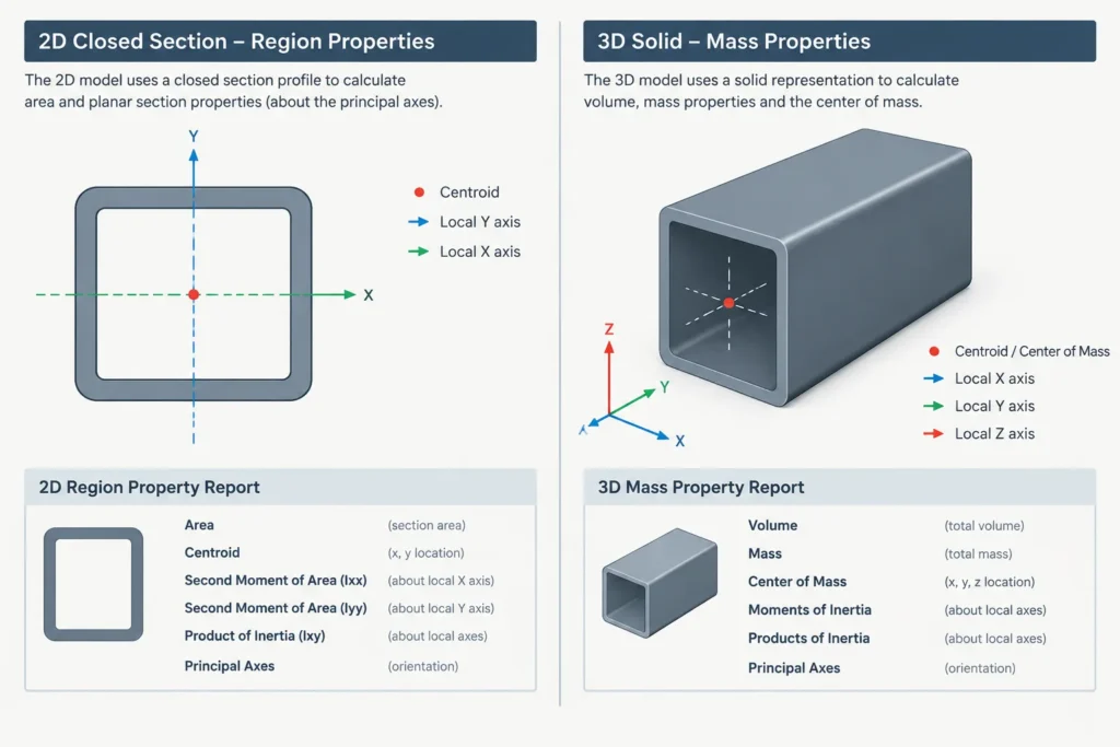
A two-dimensional section-region command and a three-dimensional solid mass-properties command may both return values labeled as moments of inertia. The results can represent different quantities.
A 2D region report may provide area, centroid coordinates, area moments about selected axes, principal moments, and product of inertia. A 3D solid report may provide volume, center of mass, and a mass-inertia tensor. If density is assigned or implied, the solid report may be evaluating the object as a body rather than as a structural cross section.
Before transferring any CAD result into a calculation, verify:
- Whether the source object is a 2D region or a 3D solid
- Whether the calculation uses area, volume, or mass
- The origin and direction of the reported axes
- Whether the axes pass through the centroid or another reference point
- The drawing units and the property units
- Whether fillets, corner radii, welds, plates, holes, or simplified geometry are included
- Whether the reported value is local, global, centroidal, or principal
A Practical Verification Workflow
- Name the required property. State whether the task needs area moment of inertia, mass moment of inertia, torsional constant, or another property.
- Identify the axis. Confirm both its direction and location. An axis with the correct label but the wrong origin can produce a different value.
- Check the units. Length4 indicates an area moment. Mass × length2 indicates a mass moment.
- Confirm the modeled object. Use cross-sectional geometry for section properties and complete solid geometry for mass properties.
- Review orientation. Rotating a steel section can exchange the property associated with the model’s horizontal and vertical axes even though the physical section has not changed.
- Compare related properties. Area, centroid, section modulus, and radius of gyration can help reveal an axis or unit mistake.
- Record the source and assumptions. Note whether the value came from a published shape table, a calculated region, or a solid-model report.
Key Takeaway
Structural steel shape tables use area moments of inertia to describe cross-sectional geometry for bending and stability applications. Mass moments of inertia describe the rotational behavior of complete objects and require mass distribution information. Because both may be labeled I, the safest practice is to check the full property name, axis definition, modeled geometry, and units every time data moves between a table, drawing, model, or analysis tool.