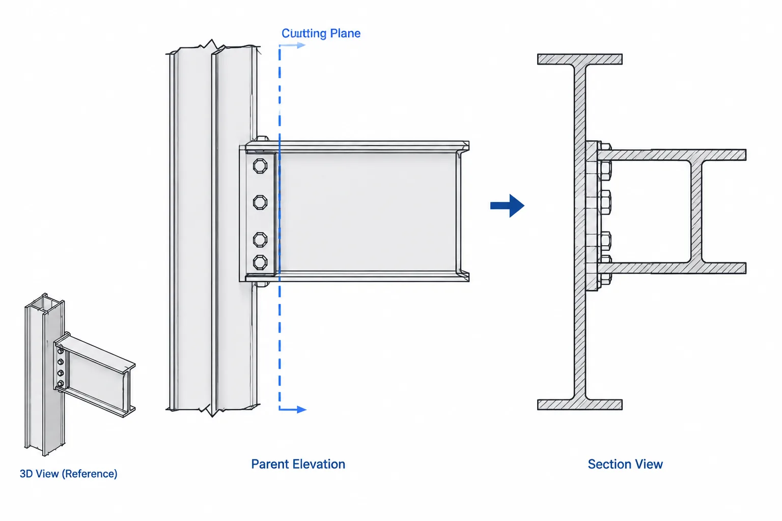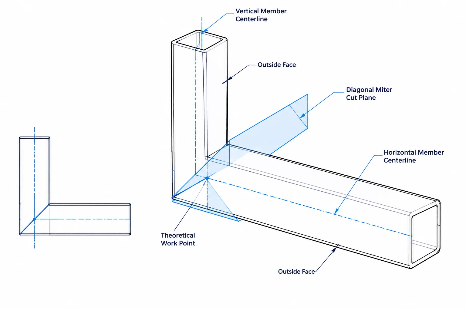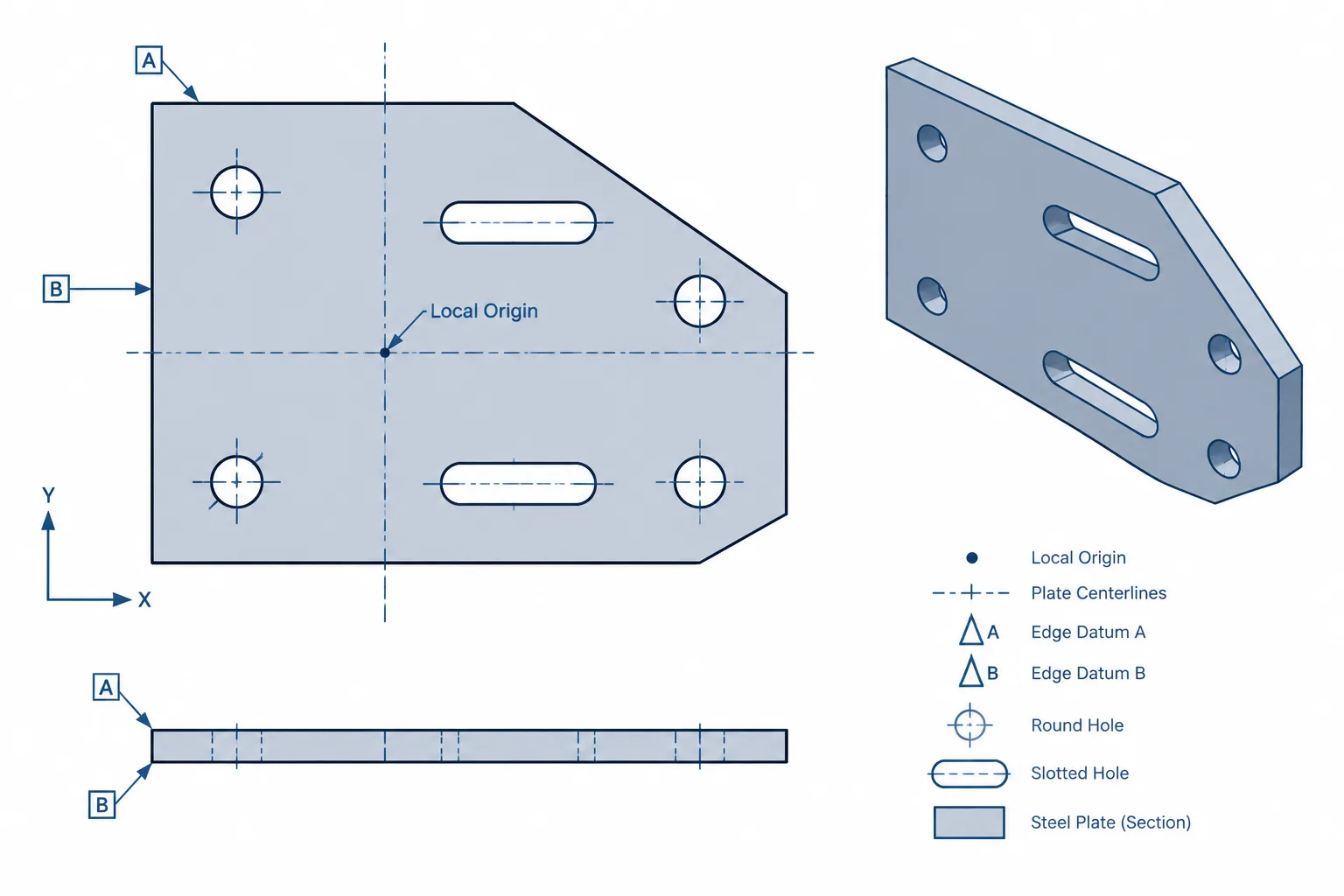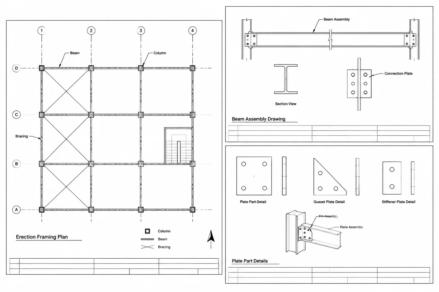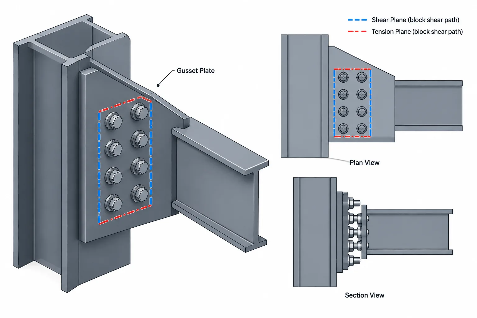
A bolt pattern is more than a collection of holes. In many structural steel connections, the location of the bolt-group centroid helps define how a load acts relative to the fasteners. It can affect the interpretation of eccentricity, the distribution of forces within the group, and the clarity of connection drawings.
For drafters and detailers, the practical task is usually geometric: place the holes correctly, establish reliable datums, and make the pattern easy to verify. For engineers, the same geometry becomes part of the connection analysis. Keeping those two uses aligned reduces errors between calculations, models, CNC data, and shop drawings.
What Is a Bolt-Group Centroid?
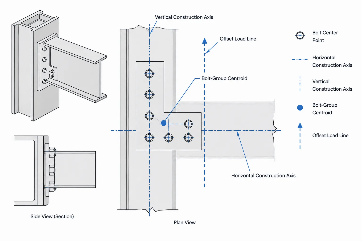
For a group of identical fasteners represented by points, the bolt-group centroid is the average location of the fastener centers. If the bolt centers have coordinates xi and yi, the geometric centroid is:
x̄ = Σxi / n
ȳ = Σyi / n
Here, n is the number of fasteners. The result is a point, not necessarily the location of an actual bolt. In a pattern with an even number of rows or columns, the centroid commonly falls between bolt lines.
This simple coordinate average is appropriate for finding the geometric center of a group of equivalent fastener points. It should not automatically be treated as a complete connection-design model. Fastener type, stiffness, load direction, connected-part behavior, hole type, and the selected analysis method can all affect how forces are evaluated.
Geometric Center, Bolt-Group Centroid, and Connection Centerline
Several different reference points may appear close together in a connection detail, but they are not interchangeable.
| Reference | Meaning | Typical use |
|---|---|---|
| Bolt-group centroid | Average position of the fastener centers | Connection analysis and geometric checks |
| Pattern bounding-box center | Center between the outermost hole coordinates | Quick CAD inspection of regular patterns |
| Plate centerline | Center of the plate width or length | Plate layout and dimensioning |
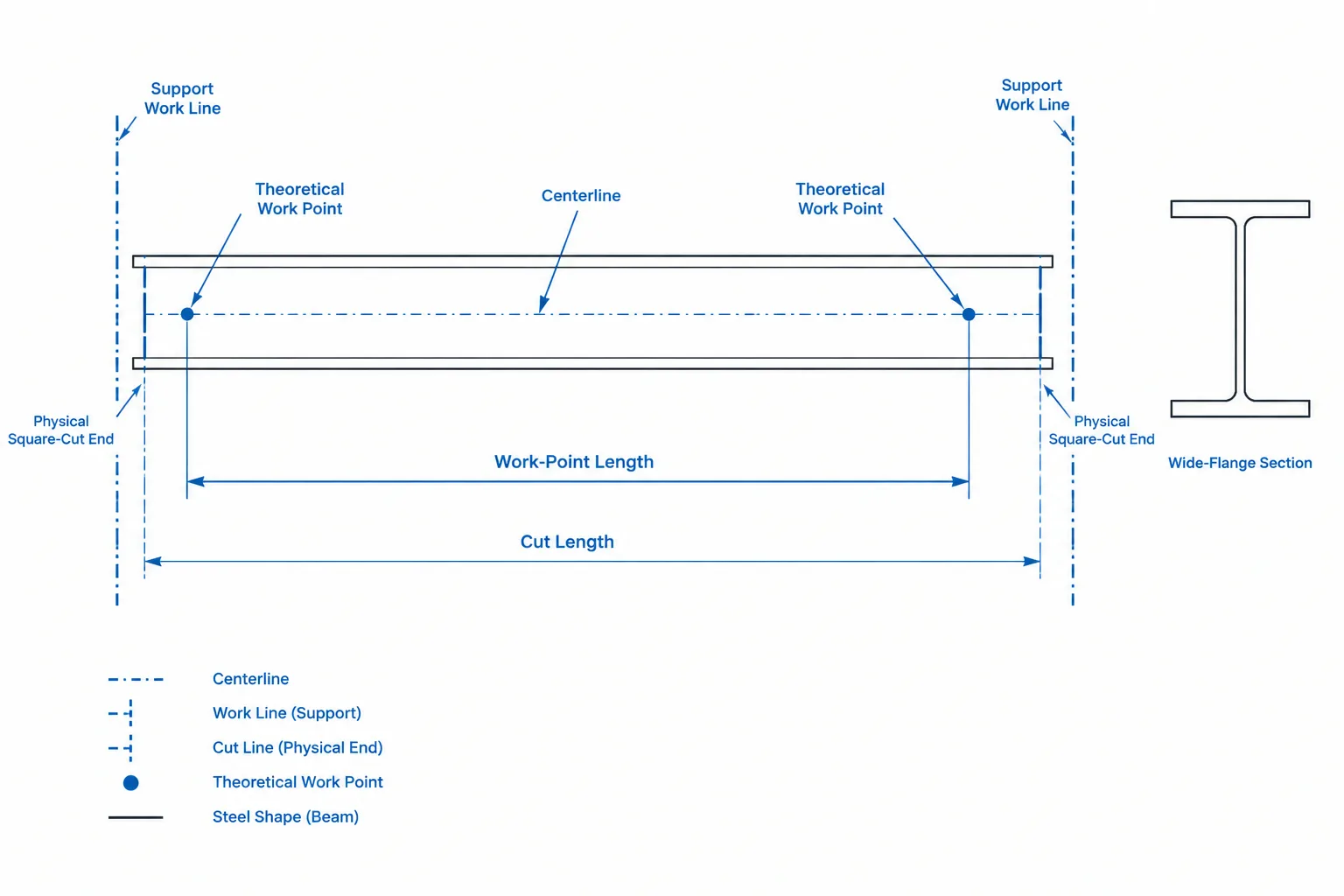
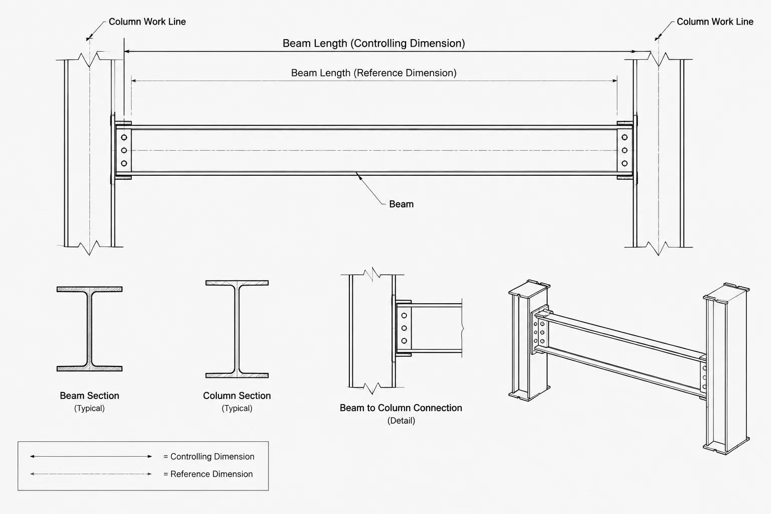
| Member work line | Reference line used to establish member geometry | Framing layout and load-path coordination |
| Load line | Line along which a force is idealized as acting | Evaluation of connection eccentricity |
These references coincide only when the geometry has been arranged that way. An offset bolt pattern may have a centroid that does not lie on the plate centerline. Likewise, a centered plate does not guarantee that the bolt group is centered on the member work line.
Regular and Irregular Bolt Patterns
Rectangular patterns
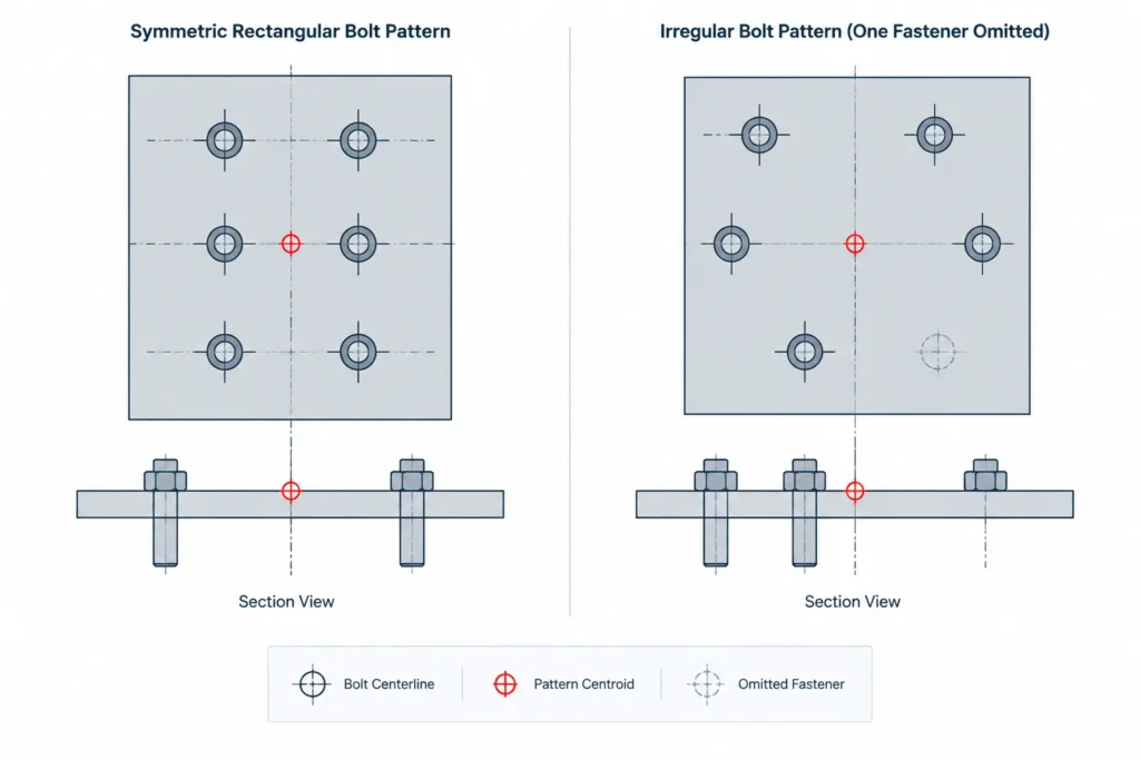
For a complete rectangular array with uniform pitch and gage, symmetry usually makes the centroid easy to identify. It lies midway between the outer bolt lines in each direction. A CAD bounding-box center can provide a useful check, although dimensions and actual hole-center coordinates should remain the controlling information.
Missing or omitted holes
A rectangular outline does not establish the centroid when a hole is removed. The centroid must be calculated from the fasteners that are actually present. This issue arises around copes, access requirements, obstructions, or connection configurations in which one portion of an otherwise regular pattern is omitted.
Staggered patterns
In a staggered group, alternate rows may have different horizontal coordinates. The centroid can still be found by averaging all bolt-center coordinates. It should not be assumed to fall on a visually prominent row, edge, or diagonal.
Unequal row populations
If one row contains more fasteners than another, the centroid shifts toward the row with more fastener points. Simply averaging the row centerlines would give the wrong answer unless each row contains the same number of bolts. A reliable method is to average every bolt coordinate or to use a weighted average based on the number of bolts in each row.
Mixed fasteners or connection components
A geometric centroid can still be calculated when a detail includes different fastener sizes or types, but its analytical meaning may be limited. Treating unlike fasteners as equivalent points can conceal differences in stiffness, strength, installation, or load transfer. The connection engineer should define the applicable analysis assumptions.
How Eccentricity Relates to the Centroid
Connection eccentricity is commonly understood as the perpendicular distance between the bolt-group centroid and the applicable line of action. When a load does not pass through the centroid, the group may be subjected to a combination of direct force and moment.
The drawing should make the underlying geometry traceable. Depending on the connection, useful references may include:
- The member work line or centerline
- The face of a supporting member
- The centerline of a beam web, angle leg, tee stem, or gusset
- The load line identified in the engineering design
- The centroid of the detailed bolt group
A dimension between convenient steel edges is not necessarily the analytical eccentricity. Rolled-shape edges, plate edges, and member faces may be offset from the work line or load path. The correct reference must be established before the distance is interpreted.
A CAD Workflow for Finding the Bolt-Group Centroid
Establish a stable coordinate system
Select drawing datums that remain meaningful if the plate size changes. A member work line, plate centerline, support face, or defined plate corner may be appropriate. Avoid deriving critical coordinates from incidental trimmed geometry.
Represent holes by true centers
Use points, center marks, or well-defined circle centers for the calculation. For slotted holes, use the specified slot center as the fastener coordinate rather than one end of the slot. The slot orientation and length are separate geometric properties.
Extract or list the coordinates
Record each center relative to the selected origin. For regular arrays, equations or associative pattern tools may reduce manual work. For irregular groups, a coordinate schedule can make omitted, duplicated, or displaced holes easier to detect.
Calculate the coordinate averages
Average the horizontal coordinates and vertical coordinates independently. Place a temporary construction point at the resulting location. Keep that point on a nonprinting construction layer unless it needs to appear in the final detail.
Compare against expected symmetry
If the group is intended to be symmetric about a centerline, the calculated centroid should lie on that centerline. If it does not, check for a missing hole, an incorrect pattern count, a displaced row, or an unintended datum offset.
Measure to the applicable load line
Once the centroid is established, measure the perpendicular relationship to the line identified by the design basis. Do not substitute a horizontal or vertical distance when the relevant load line is inclined.
Common Detailing Mistakes
- Using the plate center as the bolt-group center: This fails when edge distances differ or the pattern is intentionally offset.
- Averaging row locations without accounting for bolt count: Rows with different populations require weighting or individual coordinate averaging.
- Including construction holes: Drain, vent, erection, or other holes are not necessarily part of the structural bolt group.
- Using slot endpoints as fastener locations: Connection geometry is generally referenced to the slot center unless the design documents define another basis.
- Measuring eccentricity to a visible edge: The analytical line of action may be a work line or member centerline rather than an edge of steel.
- Ignoring mirrored geometry: Mirroring a detail can reverse the offset between the load line and bolt group even though the local pattern dimensions remain unchanged.
- Relying on a CAD block insertion point: An insertion point is a drafting convenience and may not coincide with the actual centroid.
What Should Appear on the Drawing?
The centroid itself does not always need to be dimensioned or labeled. A fabrication drawing generally needs enough controlling information to recreate and inspect the hole pattern without ambiguity. That may include gages, pitches, edge distances, end distances, row offsets, and clear datums.
When eccentricity is important to coordination, showing the member work line and the bolt-pattern relationship can improve clarity. Analytical notes should be included only when required by the project workflow and should not replace complete fabrication dimensions.
Avoid overdimensioning the same pattern from multiple origins. Redundant dimensions can conflict after revisions. A better approach is to choose a clear controlling datum system and use secondary dimensions only as identified checks or references.
Checks Before Issuing a Connection Detail
- Confirm that every structural fastener is included in the centroid calculation.
- Exclude unrelated holes unless the engineering model specifically includes them.
- Verify that slot centers, not slot ends, define fastener coordinates.
- Check the bolt group against intended symmetry and member centerlines.
- Confirm the origin, axis directions, and units used in coordinate exports.
- Compare the detailed pattern with the engineering sketch or connection model.
- Recalculate the centroid after adding, removing, or relocating a bolt.
- Verify mirrored and handed assemblies independently.
- Ensure that CNC or fabrication coordinates use the same controlling datums as the drawing.
The Practical Takeaway
The bolt-group centroid is a simple geometric concept with important consequences. For an equivalent group of fasteners, it comes from the average of the bolt-center coordinates. Its location should be distinguished from the plate center, member work line, pattern bounding-box center, and load line.
In CAD and steel detailing, the most dependable workflow is to establish stable datums, model true hole centers, calculate from the actual pattern, and recheck the centroid whenever the layout changes. Engineering evaluation is still required to determine how the connection transfers load and which analytical method applies, but accurate, traceable geometry gives that evaluation a reliable foundation.