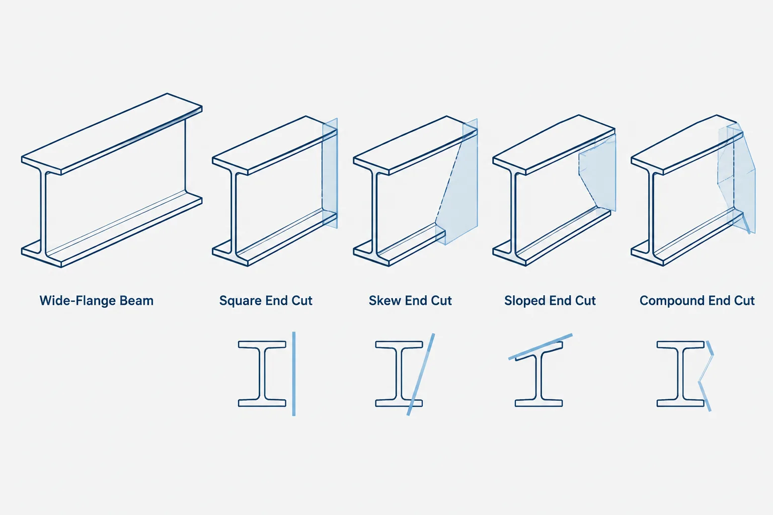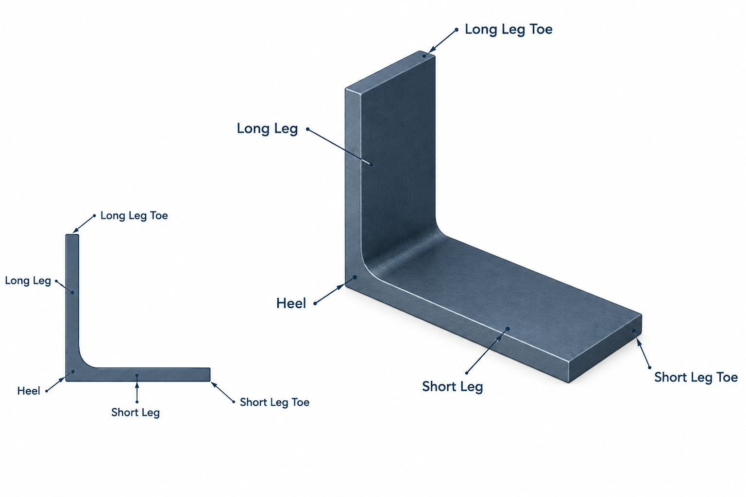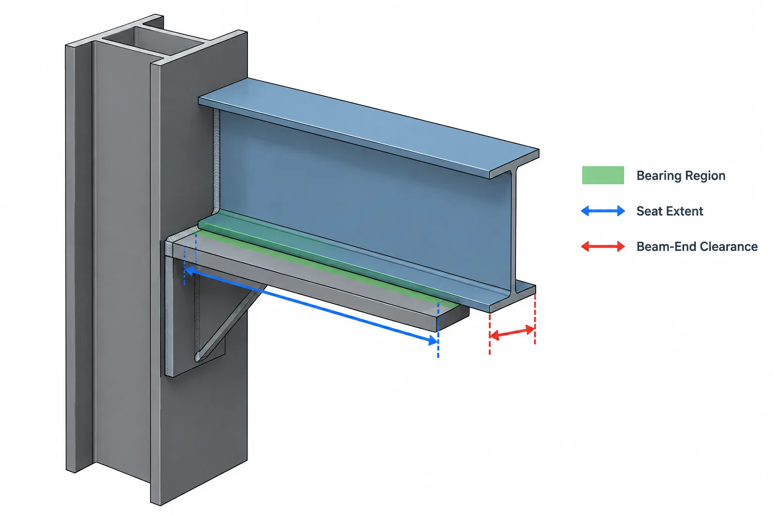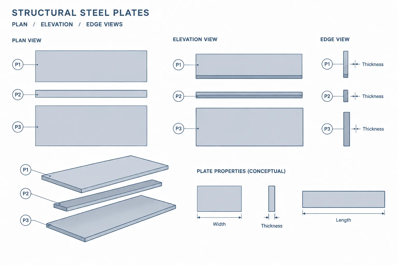
Steel column splice detailing is more than drawing plates and bolts between two vertical members. A complete splice must communicate where one column segment ends, where the next begins, how the members align, and which connection geometry has been established by the structural design. It must also account for fabrication, shipping, erection, and access.
The detailer should not infer splice capacity or select connection components without appropriate design information. The detailing task is to convert the specified splice concept into coordinated shop and erection information while identifying missing or conflicting requirements before fabrication.
Why columns are divided into spliced segments
A building column may extend through several levels in the structural model, but it is not always fabricated or erected as one continuous piece. Splices divide the column into manageable shipping and erection segments. Their locations may also correspond to changes in shape, weight series, orientation, material, or framing configuration.
A splice location affects more than the column itself. It can influence beam connections, deck support, temporary stability, fireproofing continuity, architectural enclosures, and the sequence used to erect the frame. Moving a splice for convenience should therefore be treated as a coordinated design change rather than a routine drafting adjustment.
Establish the controlling splice elevation
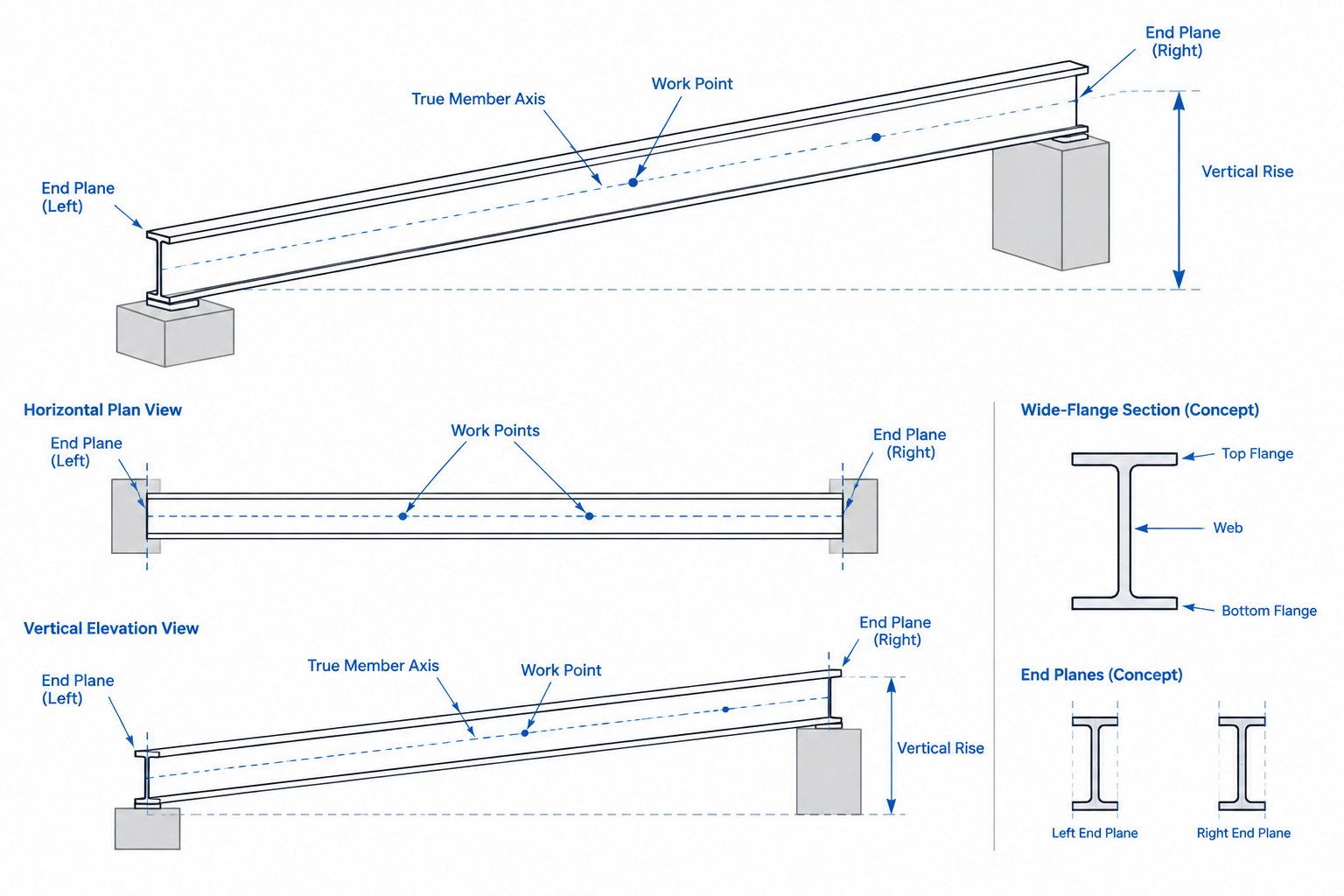
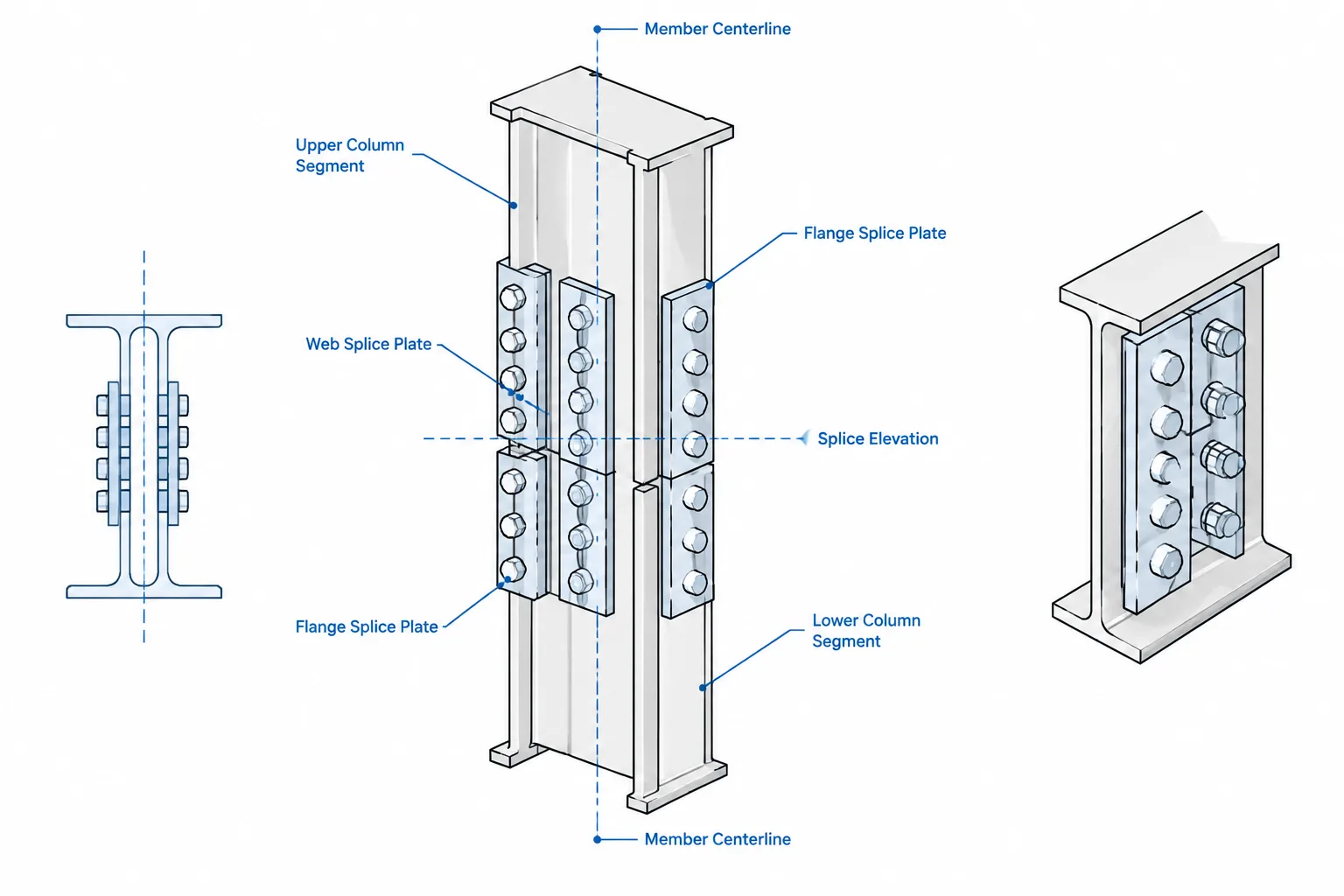
The first step is identifying what the stated splice elevation represents. Depending on project conventions, an elevation may refer to the end of the lower column, the end of the upper column, the contact plane between members, or a work point associated with the splice assembly.
A clear detail distinguishes among:
- The nominal splice elevation shown on the design drawings
- The actual cut elevation of each column segment
- Any erection gap or fitted bearing interface
- The top and bottom extents of splice plates
- Nearby floor, beam, slab, and fireproofing elevations
These references should not be assumed to coincide. If the connection includes a gap, filler, cap plate, bearing plate, or other intervening component, the end locations of the two column shafts may differ from the nominal splice work point.
Check the surrounding framing zone
A splice that looks clear in an isolated elevation can conflict with beams, joists, braces, slab edges, or connection plates when placed in the full model. Review the splice in plan, elevation, and three-dimensional context. Particular attention should be given to bolt access and weld access on faces occupied by framing connections.
Define how the upper and lower columns align
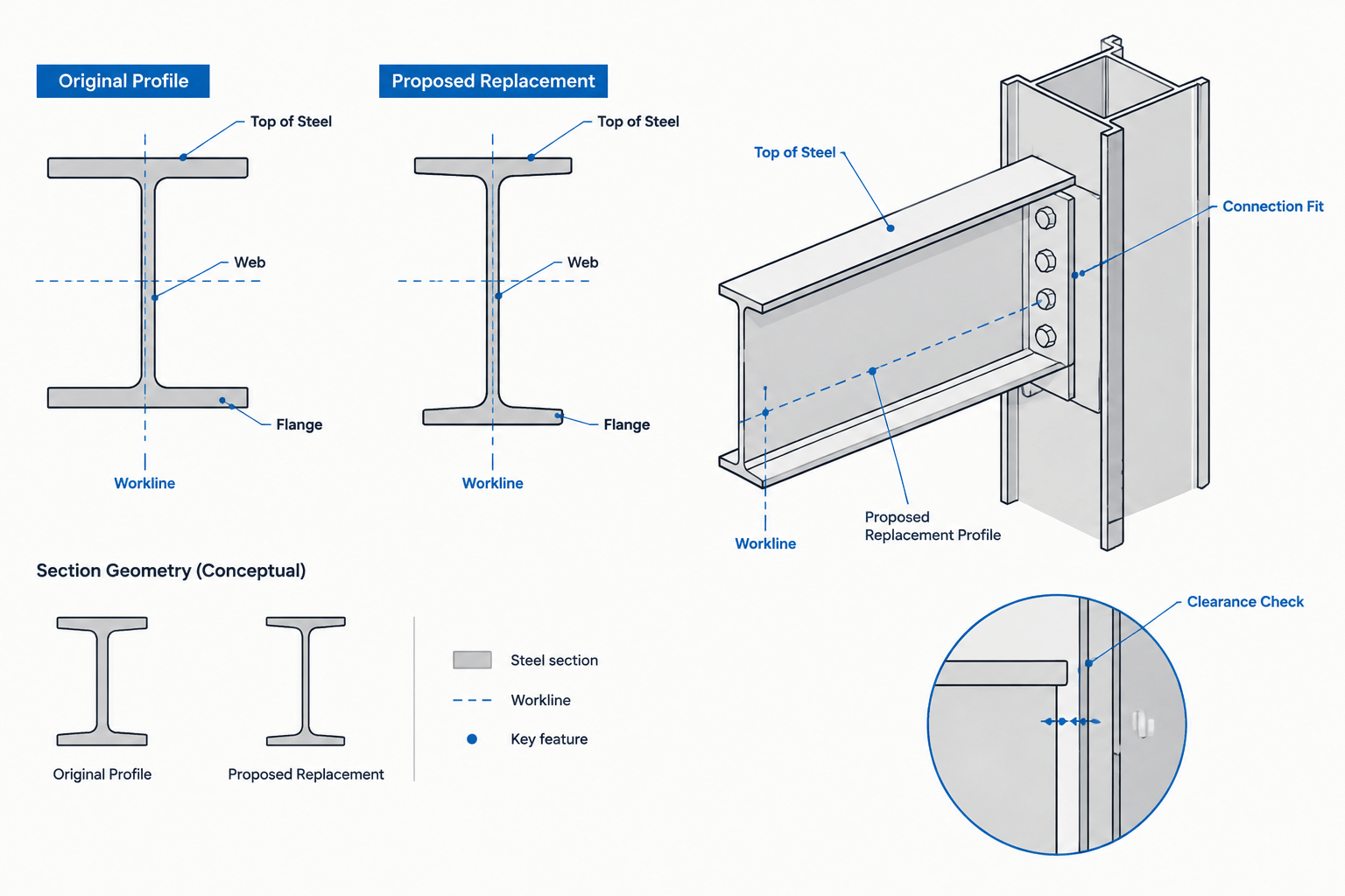
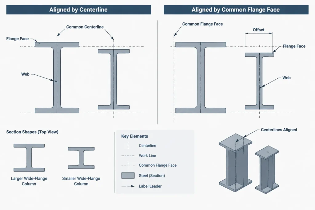
When the column shapes above and below are identical, alignment may appear straightforward. Even then, the drawing should establish the controlling work line and orientation. When the shapes differ, several possible alignment rules may produce different physical results.
| Alignment basis | What it controls | Common coordination concern |
|---|---|---|
| Centerline or centroid alignment | Places designated member reference points on a common line | Flange faces may not remain flush when section dimensions differ |
| Web centerline alignment | Centers the webs in a selected direction | Changes in flange width may create unequal projections |
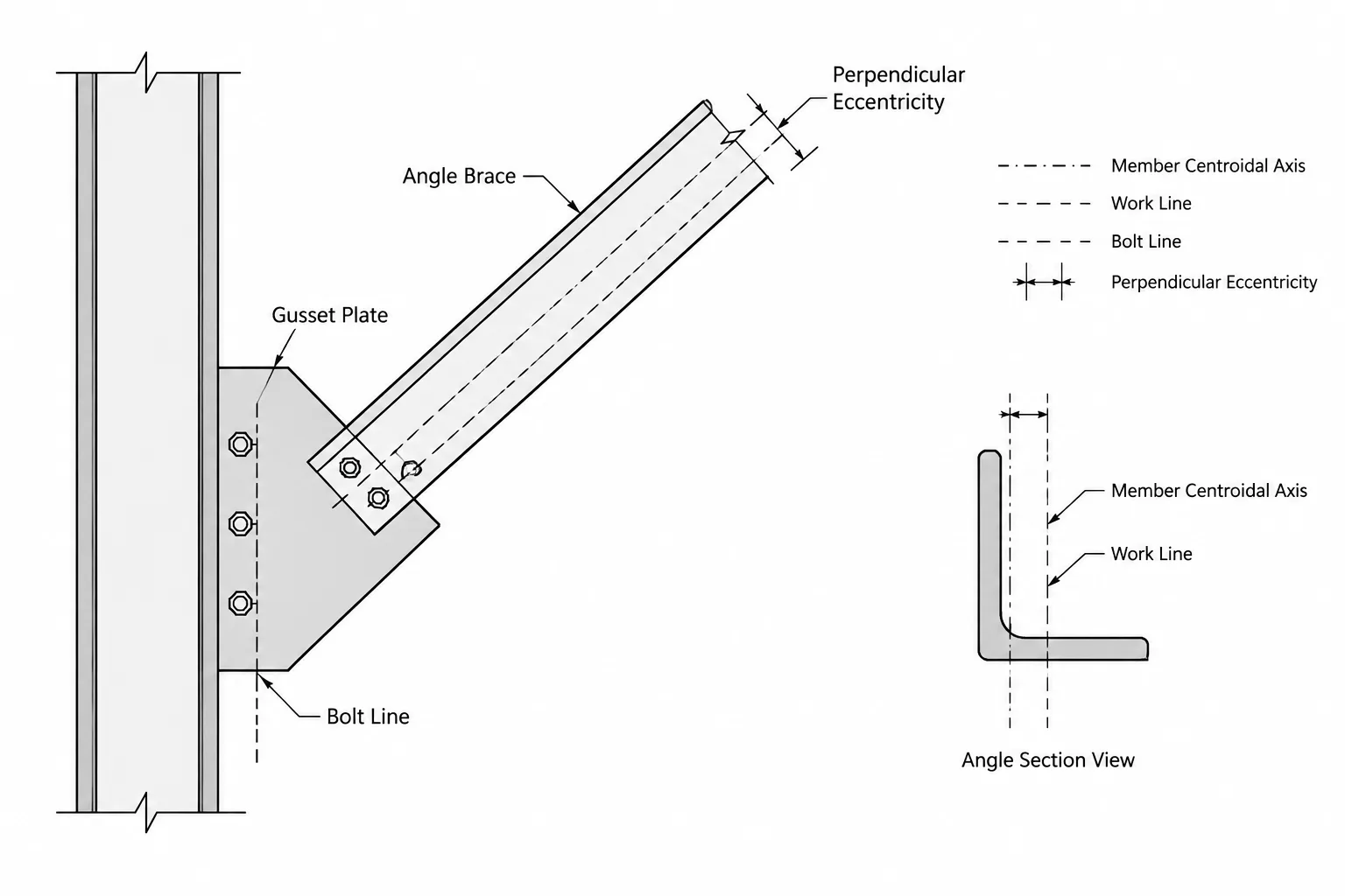
| One flange face held flush | Maintains a common exterior or framing face | Introduces an offset between member centerlines |
| Grid or work-line offset | Locates each member from a project reference | Requires explicit offset dimensions and direction |
No alignment method should be assumed solely from a schematic line on a plan. The detailer should compare column schedules, orientation symbols, architectural control dimensions, and framing elevations. If an offset exists, it should be visible and dimensioned in the appropriate views.
Keep section orientation unambiguous
Wide-flange columns can be rotated while retaining the same shape designation. Show flange and web directions relative to grids or adjacent framing. For rectangular HSS, orientation is especially important because turning the section changes which face receives a plate, beam, or brace connection.
Upper and lower segments should be checked independently. A transition between differently oriented members may require geometry that cannot be represented accurately by a generic splice symbol.
Recognize common splice configurations
The connection type must come from the project design information. The following categories are useful for organizing the detail, but they do not determine capacity or required components.
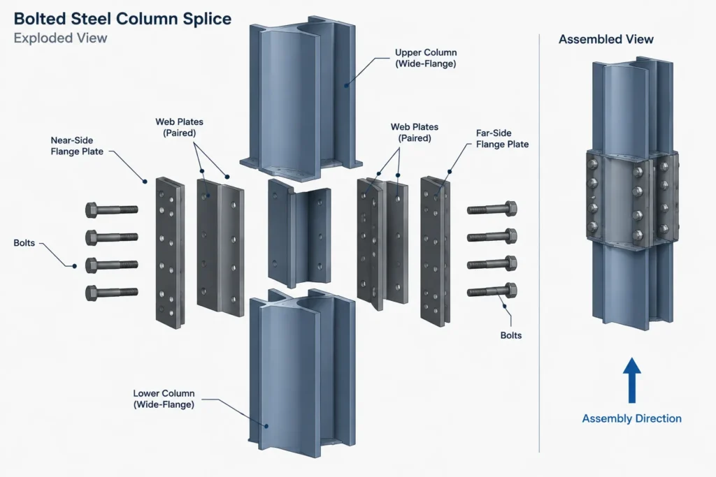
Bolted flange-and-web splice
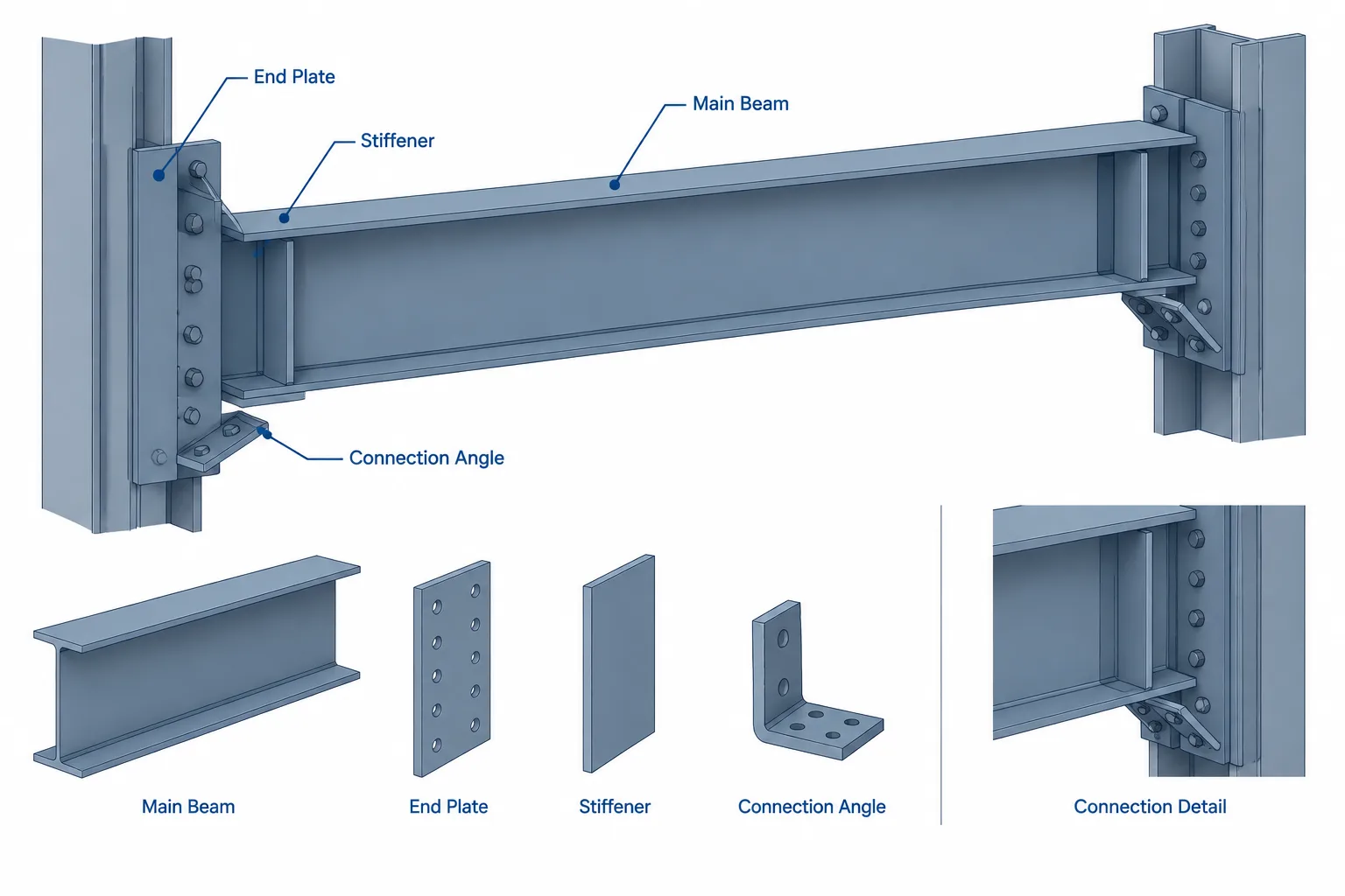
A rolled I-shaped column may use plates at the flanges, the web, or both. The drawing must identify which plates are on the near and far sides, whether pieces are paired, and how they relate to the column ends. Bolt patterns should be coordinated with flange thickness, web geometry, rolled fillets, and tool access.
Welded column splice
A welded splice may connect member ends directly or use plates as part of the connection. Drawings should distinguish shop welds from field welds and communicate required preparation without inventing weld requirements. Access, backing or support components, inspection needs, and erection restraint require project-specific coordination.
End plate, cap plate, or bearing-type arrangement
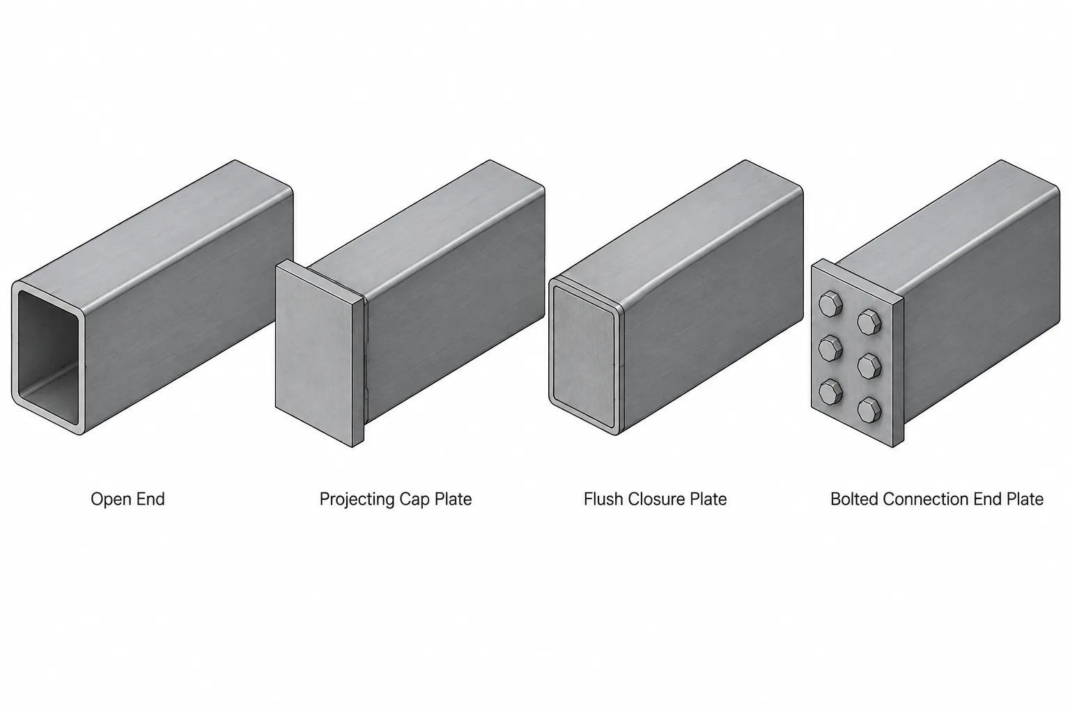
Some splice concepts transfer forces through plates at the ends of the column segments. The detail must make clear whether plates are attached to one segment or both, how they align, and whether bolts or welds connect the resulting assembly. Plate terminology alone does not establish whether surfaces are intended to bear or how loads are distributed.
HSS column splice
HSS splices may use external plates, end plates, internal elements, or other engineered arrangements. Access to the closed section is a central detailing issue. The detailer should not assume that a nut, backing element, weld, or internal plate can be installed after the section is closed. Corner radii and the location of the weld seam can also affect plate fit and weld placement.
Detail plates from verified geometry
Splice plates should be developed from actual member geometry and the designed connection layout, not from a generic block. For rolled shapes, verify flange width, flange thickness, web thickness, and fillet regions using the applicable project reference. For HSS, account for rounded corners and distinguish nominal dimensions from the geometry needed for fit-up.
Each plate should have enough information to be fabricated without scaling the drawing. Depending on the project workflow, this may include:
- Plate mark and quantity
- Thickness and overall outline
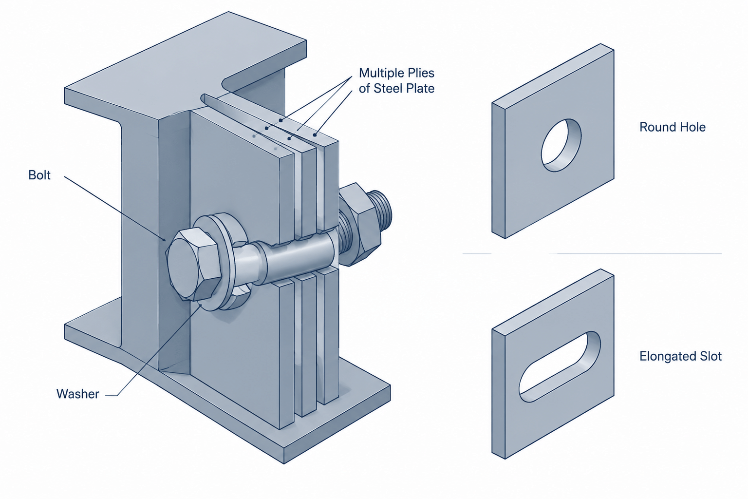
- Hole locations and hole descriptions
- Orientation and face of installation
- Weld locations and shop or field designation
- Relationship to the splice work point and member ends
- Required fillers, shims, or pack plates identified by the design
Mirrored plates deserve special attention. Two plates may share an outline but not be interchangeable if hole patterns, clipped corners, weld preparations, or orientation marks differ.
Coordinate erection and installation access
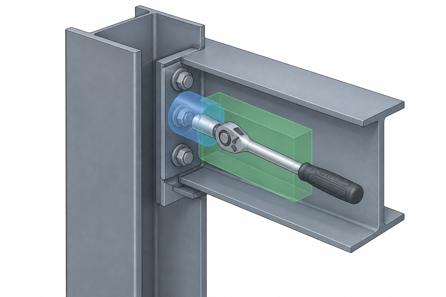
A connection can be drawable yet difficult to assemble. Review how the upper column will be lowered into position, how it will be temporarily stabilized, and how workers will reach bolts or field welds. Avoid relying on an installation sequence that traps a plate or makes a fastener inaccessible.
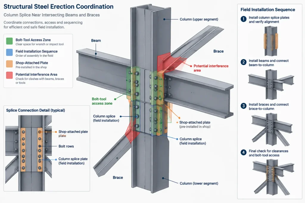
Items to review include:
- Whether splice plates are shop-attached to a particular column segment
- Whether bolts can be inserted and tightened around adjacent framing
- Whether field welds remain accessible after beams or braces are installed
- Whether projecting plates interfere with shipping or lifting
- Whether loose components have clear marks and installation orientation
- Whether temporary erection provisions must be coordinated separately
Shop-attaching selected components can simplify field work, but it may increase shipping width or create handling hazards. The preferred arrangement should be coordinated with the fabricator and erector rather than assumed by the drafter.
Show the splice consistently across drawing types
Column splice information often appears in design plans, elevations, schedules, erection drawings, assembly drawings, and part details. These views must agree on member designation, orientation, elevation, and connection identity.
An erection drawing should make the splice easy to locate in the structure. An assembly drawing should show how connection material attaches to the column shaft. Part drawings should provide fabrication geometry for each plate or fitting. A typical detail may explain a repeated concept, but exceptions still need to be identified where member sizes, offsets, or surrounding framing differ.
Use sections where elevation views are insufficient
A single elevation may hide near-side and far-side plates or make flange orientation unclear. Add plan sections or cross-sections to show the relationship among webs, flanges, plates, and bolt lines. Use consistent viewing directions and label section cuts so that mirrored interpretations are not possible.
Column splice coordination checklist
- Confirm the design-defined splice type and required components.
- Identify the exact meaning of the splice elevation.
- Verify the cut length of both column segments.
- Confirm grid location, work lines, offsets, and section orientation.
- Compare upper and lower shape geometry rather than assuming a match.
- Check plates against rolled fillets, HSS corners, and adjacent connections.
- Confirm near-side, far-side, inside, and outside plate locations.
- Review bolt tightening and field-weld access.
- Coordinate shop-attached and field-installed components.
- Check shipping, lifting, and erection implications.
- Make erection, assembly, and part drawings consistent.
- Submit unresolved alignment or design issues through the project clarification process.
Final drafting principle
A reliable column splice detail connects three kinds of information: the structural design intent, the exact geometry of the adjoining members, and the practical sequence of fabrication and erection. When the splice elevation, alignment basis, plate orientation, and access conditions are explicitly shown, the drawing becomes a useful production document rather than a symbolic representation. Where those items are not defined, clarification is safer than filling gaps with drafting assumptions.