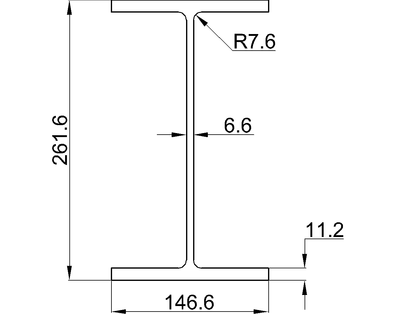
The W10x12 is a W beam reference for identifying the section geometry and material quantity used in structural steel drafting and preliminary coordination. The source data on this page lists the section dimensions, thicknesses, root fillet radius, sectional area, and unit weight.
Use the dimensional listing together with the downloadable DWG when checking layouts, preparing details, or comparing W-shape references. For design work, confirm the project requirements, material specification, connection assumptions, and applicable design checks before using any shape in a structure.
W Beam
refer to : AISC 16
the American Institute of Steel Construction (AISC) Specification for Structural Steel Buildings (AISC 360-16), which is the 2016 edition of the AISC Specification for Structural Steel Buildings. It provides guidelines and requirements for the design, fabrication, and erection of steel structures in the United States.
Depth : 250.7 mm
Width : 100.6 mm
Web Thickness : 4.8 mm
Flange Thickness : 5.3 mm
Root Fillet Radius : 7.6 mm
Sectional Area : 22.84 cm2
Unit Weight : 17.9 kg/m
How to read the W10x12 reference
The source block separates the profile into the dimensions that define its rolled shape. Overall depth and flange width describe the envelope of the section, while web and flange thicknesses describe the main plate elements. The root fillet radius identifies the curved transition between the web and flange and is important when interpreting detailed geometry or preparing accurate drawings.
Why the listed properties matter
- Sectional area: provides the cross-sectional quantity used in calculations involving gross steel area and material takeoffs.
- Unit weight: supports estimating, handling, shipping, and framing coordination. It should not be treated as a substitute for a project-specific strength or stability check.
- Dimensions and thicknesses: help drafters coordinate clearances, framing intersections, connection details, and member representations.
Using the DWG reference
The downloadable DWG is useful for CAD workflows that require a graphical representation of the W10x12 profile. Before inserting it into a production drawing, check the drawing units, scale, orientation, layer conventions, and file geometry against the source listing and the project template.
For related background, connect this page with the site’s references on W-shapes, steel section properties, structural steel terminology, and connection detailing. Those topics help explain how a shape designation, profile geometry, and design documentation fit together.
Design and detailing considerations
A shape reference identifies geometry; it does not by itself establish member capacity. Actual selection may depend on loading, unbraced length, support conditions, lateral stability, connection design, fabrication requirements, corrosion provisions, and the governing project criteria. Coordinate the reference dimensions with the engineer’s calculations and the approved fabrication information.
Frequently asked questions
What type of steel shape is the W10x12?
The page identifies the W10x12 as a W beam. The W designation is used for a wide-flange structural steel profile, while the complete designation distinguishes this reference from other W-shape listings.
What information is included for the W10x12?
The source lists the profile depth, width, web thickness, flange thickness, root fillet radius, sectional area, and unit weight. These values are the authoritative local data for this page.
Is the W10x12 reference suitable for structural design by itself?
No. The listed geometry and unit weight are reference information, not a complete design check. Member selection must be verified against project loads, boundary conditions, material requirements, stability considerations, connections, and the applicable design basis.
What is the DWG file used for?
The DWG provides a CAD reference for representing the W10x12 profile in drafting and coordination workflows. Verify units, scale, and geometry before using the file in a production document.
Why is the root fillet radius listed?
The root fillet is part of the rolled section geometry at the web-to-flange transition. Including it helps users distinguish the actual profile form from a simplified sharp-corner sketch when coordinating details or CAD geometry.