UPE 220 is a European parallel flange channel designation used to identify a hot-rolled structural steel section. This reference page brings together the profile dimensions, sectional area, unit weight, and the cited EN 10365:2017 standard reference for the section.
Use the data below when checking a drawing, reviewing a steel schedule, coordinating a connection detail, or selecting a matching CAD reference. The listed values describe the section geometry and mass; they do not by themselves establish structural capacity or design suitability.
UPE 220
Parallel Flange Channels
refer to : EN 10365:2017
a European standard that defines the dimensions, tolerances, and sectional properties for hot-rolled steel channels, I-beams, and H-beams used in construction and engineering. It ensures uniformity and compatibility across European structural steel products.
Dimension : 220x85x6.5×12
Depth : 220 mm
Width : 85 mm
Web Thickness : 6.5 mm
Flange Thickness : 12 mm
Root Fillet Radius : 13 mm
Sectional Area : 33.9 cm2
Unit Weight : 26.6 kg/m
How to read the UPE 220 designation
The profile name identifies the UPE series and its nominal section size. The dimension string presents the main geometric identifiers in sequence: overall depth, flange width, web thickness, and flange thickness. These values help distinguish UPE 220 from other parallel flange channels and provide a concise way to communicate the section in drawings and schedules.
UPE 220 geometry and reference data
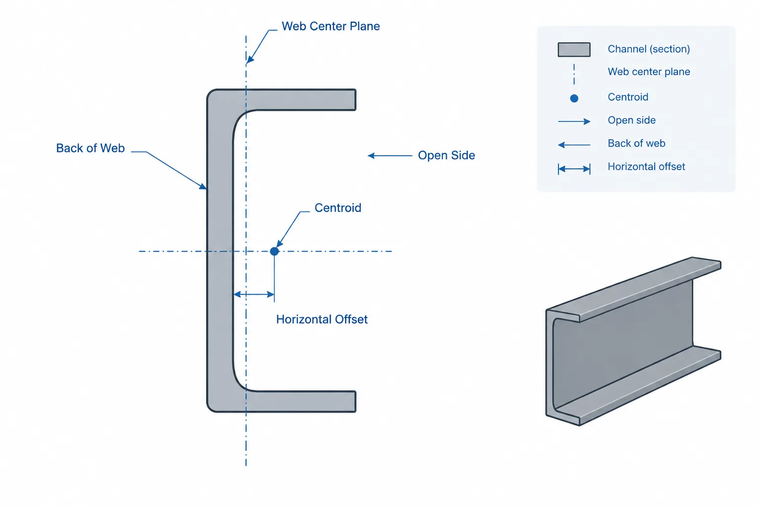
The source data gives the overall depth and width together with the web and flange thicknesses. It also lists the root fillet radius, sectional area, and unit weight. The root fillet is part of the rolled transition between the web and flange, so it should be considered when checking clearances, contact surfaces, plate fit-up, and detailed CAD geometry.
Sectional area and unit weight are useful for quantity review and preliminary material takeoffs. They should not be treated as a substitute for verified design calculations. Resistance, stability, deflection, connection behavior, and fabrication requirements depend on the complete design context and the applicable project requirements.
EN 10365:2017 reference
The page cites EN 10365:2017, which provides a common framework for dimensions, tolerances, and sectional properties for hot-rolled structural steel channels and related sections. Referencing the standard helps designers, detailers, fabricators, and suppliers use the same profile definition when coordinating documents.
Drafting and CAD considerations
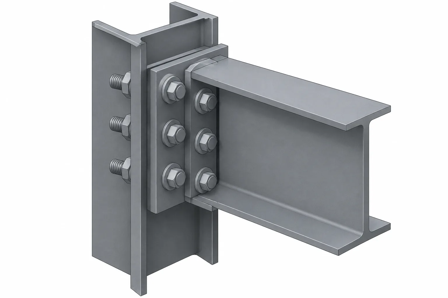
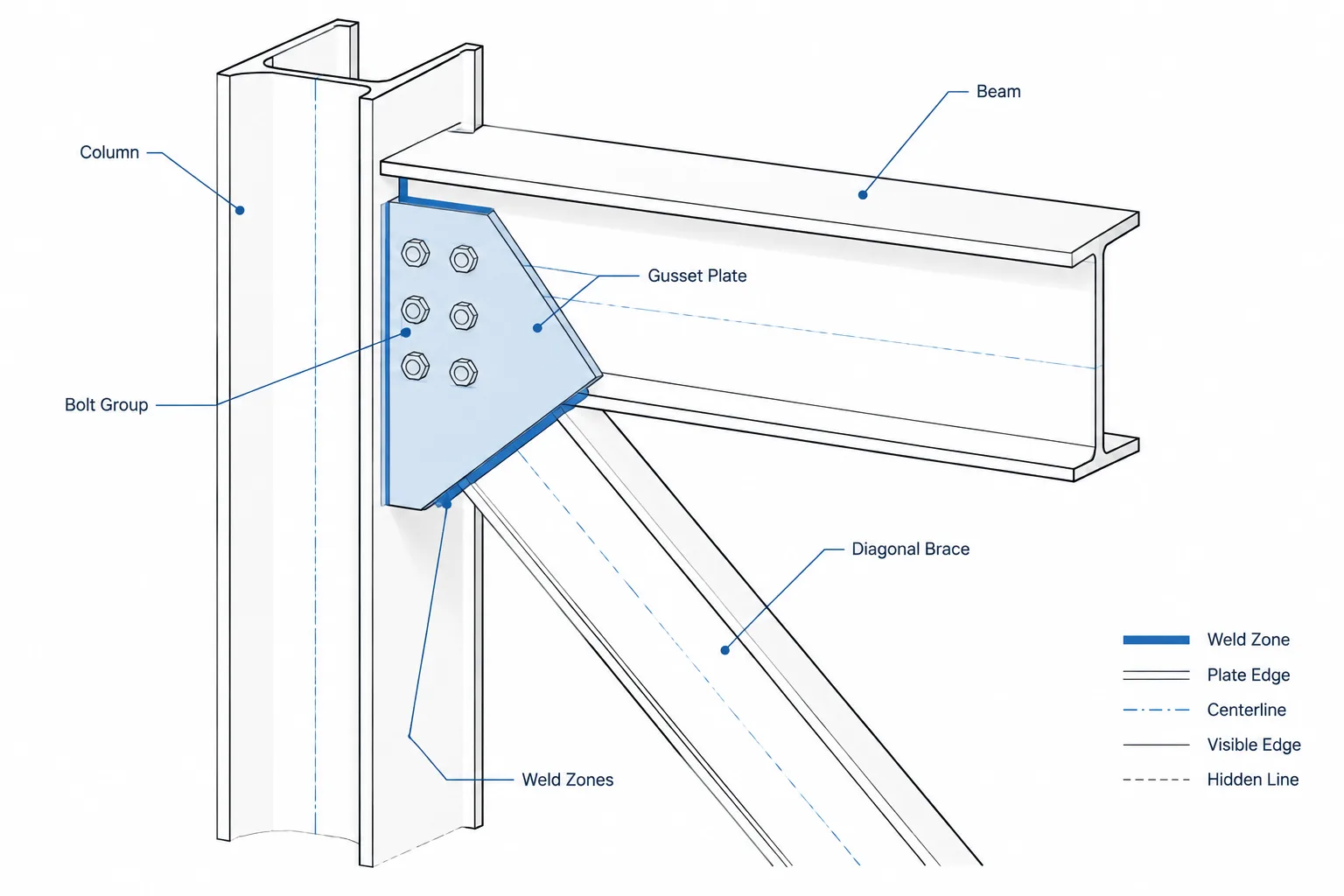
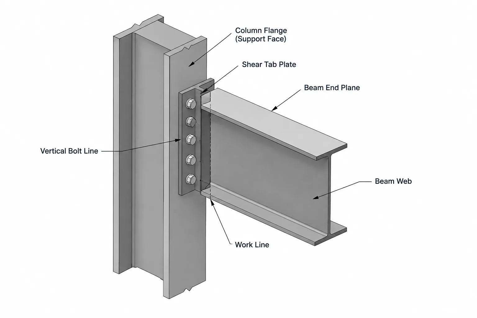
When placing UPE 220 in a model or drawing, confirm the section orientation, flange direction, connection interfaces, and required clearance around the root fillets. The downloadable DWG can support drafting and coordination, but the model should still be checked against the project’s approved section data and fabrication requirements.
Related internal references may include pages for parallel flange channels, UPE sections, steel section properties, EN 10365 profiles, and structural steel CAD blocks. These topics provide useful comparison and navigation without replacing the authoritative values on this page.
Frequently asked questions
What is UPE 220?
UPE 220 is a parallel flange channel designation for a hot-rolled structural steel section. The page identifies its geometry and reference data using the cited European standard.
What does the UPE 220 dimension string describe?
The dimension string describes the section’s overall depth, flange width, web thickness, and flange thickness. These identifiers are used to distinguish the profile from other UPE sizes and channel series.
Why is the root fillet radius important?
The root fillet is the curved transition between the web and flange. It can affect contact, clearance, detailing, and the accuracy of a CAD representation, especially where plates or connection components meet the rolled section.
Does the listed unit weight determine structural capacity?
No. Unit weight supports material estimates and quantity checks, but structural capacity also depends on loading, restraint, material requirements, stability, connections, and the governing design method.
Can the DWG file be used directly for fabrication?
The DWG is a drafting reference. Before fabrication, verify the geometry, orientation, tolerances, project requirements, and approved engineering documents.