UBP 305x305x223 is a Universal Bearing Pile profile identified on this page by its source-listed dimensions, section area, unit weight, and standards reference. The information below supports section identification, drawing coordination, preliminary reference work, and CAD-based detailing.
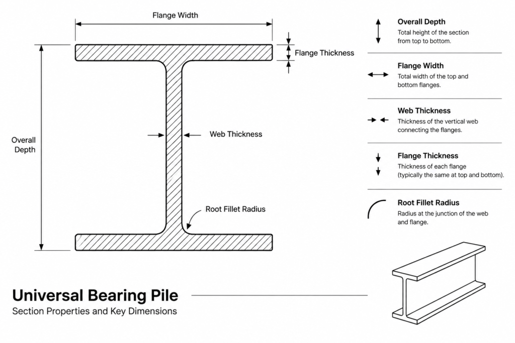
The designation is a convenient profile name, but it should not replace the actual dimensional data when creating or checking a drawing. In particular, use the listed depth, width, web thickness, flange thickness, and root fillet radius when comparing the profile with a model, schedule, or fabrication detail.
UBP 305x305x223
Universal Bearing Pile
refer to : EN 10365:2017
a European standard that defines the dimensions, tolerances, and sectional properties for hot-rolled steel channels, I-beams, and H-beams used in construction and engineering. It ensures uniformity and compatibility across European structural steel products.
Dimension : 337.9×325.7×30.3×30.4
Depth : 337.9 mm
Width : 325.7 mm
Web Thickness : 30.3 mm
Flange Thickness : 30.4 mm
Root Fillet Radius : 15 mm
Sectional Area : 284 cm2
Unit Weight : 222.9 kg/m
How to Read the UBP 305x305x223 Data
The listed overall depth is 337.9 mm, while the overall width is 325.7 mm. These values define the principal outside dimensions of the cross-section. They are distinct from the nominal numbers used in the section designation.
- Web thickness: The 30.3 mm value describes the central web thickness.
- Flange thickness: The 30.4 mm value describes the listed flange thickness.
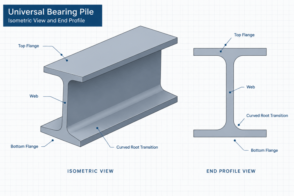
- Root fillet radius: The 15 mm radius identifies the curved transition between the web and flange.
- Sectional area: The listed gross cross-sectional area is 284 cm².
- Unit weight: The listed linear mass is 222.9 kg/m.
Designation Versus Detailed Geometry
The UBP designation provides a recognizable section reference, but its nominal numbers should not be treated as exact outside dimensions. For drafting and model verification, compare the complete designation and the detailed dimensions together. The final designation number also should not be substituted for the more precise unit-weight value shown in the source data.
Using the DWG in a CAD Workflow
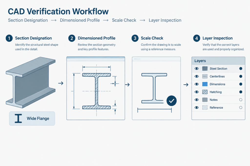
The downloadable drawing can help users place the profile into section views, pile layouts, connection studies, and general arrangement drawings. After opening the file, confirm the drawing units, measure the profile, inspect the web-to-flange transitions, and compare the geometry with the published values on this page.
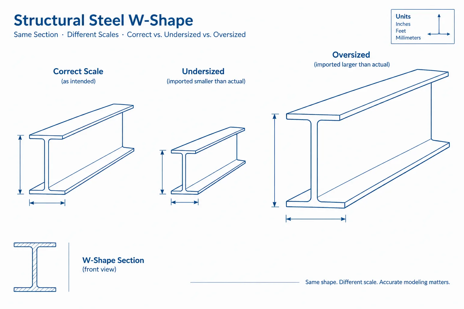
Also review layers, line types, insertion position, and object scale before incorporating the geometry into another file. Imported or converted CAD content can retain correct proportions while still entering a project drawing at an unintended scale.
Related Reference Topics
Useful related subjects include Universal Bearing Pile sections, steel section designation conventions, gross sectional area, unit weight, root fillet geometry, and CAD profile verification. These topics provide context for interpreting the data without treating a section drawing as evidence of structural capacity or project suitability.
Engineering and Detailing Limitations
Section dimensions and CAD geometry do not establish load capacity, connection adequacy, durability, or suitability for a particular foundation or structural system. Project use requires review of the applicable design basis, material specification, member length, loading, stability, connection conditions, and current project requirements by a qualified professional.
Frequently Asked Questions
What does UBP mean on this page?
UBP identifies the profile as a Universal Bearing Pile.
What are the overall dimensions of UBP 305x305x223?
The source lists an overall depth of 337.9 mm and an overall width of 325.7 mm. The complete listed dimension is 337.9×325.7×30.3×30.4.
What unit weight is listed for this section?
The listed unit weight is 222.9 kg/m. This is a linear mass value rather than a total member weight.
Which standard is referenced?
The source content refers to EN 10365:2017. Users should confirm that the cited reference and any project-specific requirements are appropriate for their work.
Can the DWG be used directly in a project drawing?
It can serve as a drafting reference, but its units, scale, dimensions, layers, and insertion position should be checked first. The drawing does not replace structural design or project-specific verification.
Why do the designation numbers differ from the listed dimensions?
A section designation functions as a standardized identifier and should not be interpreted as a complete set of exact geometric dimensions. Use the detailed values supplied with the profile when checking CAD geometry or preparing dimensions.