This page provides the published profile data and CAD resource for the UB 1000x400x412 universal beam. Use the reference information to identify the section, interpret its principal dimensions, and check the accompanying drawing before incorporating it into a detailing workflow.
The section designation is a convenient profile identifier rather than a substitute for the listed geometry. For accurate drafting, review the stated depth, flange width, web thickness, flange thickness, root fillet radius, sectional area, and unit weight individually.
UB 1000x400x412
Universal Beams
refer to : EN 10365:2017
a European standard that defines the dimensions, tolerances, and sectional properties for hot-rolled steel channels, I-beams, and H-beams used in construction and engineering. It ensures uniformity and compatibility across European structural steel products.
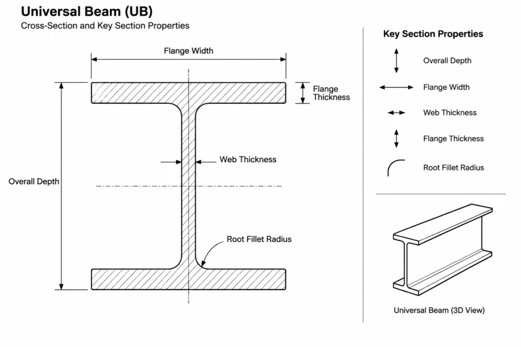
Dimension : 1008x402x21.1×40
Depth : 1008 mm
Width : 402 mm
Web Thickness : 21.1 mm
Flange Thickness : 40 mm
Root Fillet Radius : 30 mm
Sectional Area : 525.1 cm2
Unit Weight : 412.2 kg/m
How to read the UB profile information
The compact dimension sequence identifies the section depth, flange width, web thickness, and flange thickness. These values describe the main outline of the I-shaped profile, while the root fillet radius defines the curved transition where the web meets each flange.
The dimensional values are especially important when creating connection details. A simplified rectangular web-and-flange outline may be adequate for some diagrams, but the root fillets can affect local clearances, fitted components, cope geometry, and interference checks.
Designation and listed unit weight
The final part of the UB 1000x400x412 designation functions as part of the recognized section name. The source data separately lists the unit weight as 412.2 kg/m. When preparing schedules, bills of materials, or model metadata, retain the complete section designation while using the explicitly listed unit weight where that field is required.
Understanding sectional area and unit weight
Sectional area represents the steel area visible in a cross-section perpendicular to the member length. It is not the exterior surface area of the beam. Designers use section area in calculations and reference workflows, while estimators and detailers commonly use unit weight to relate member length to material quantity.
Unit weight is expressed per unit length, so it should not be treated as the total weight of a member until the actual member length and the project’s calculation conventions have been considered. Connections, plates, bolts, weld metal, coatings, and other attached items are separate from the rolled-section value.
Using the DWG in a CAD workflow
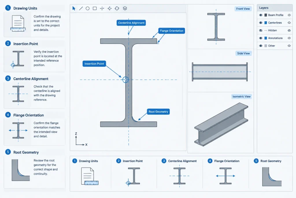
- Confirm drawing units: Check the imported file against the published dimensions rather than relying only on automatic unit detection.
- Verify the section identity: Keep the full UB designation attached to the block, layer, object data, or drawing note.
- Inspect the root region: Confirm that flange-to-web curves have not been removed or distorted during conversion.
- Check insertion and alignment: Review the origin, centerlines, rotation, and flange orientation before positioning the profile in a detail.
- Avoid scaling by eye: If the geometry does not match the stated profile data, investigate units or import settings instead of applying an arbitrary scale factor.
- Retain editable source geometry: Keep an unmodified copy before trimming, exploding, offsetting, or adapting the profile for a connection detail.
Related reference topics
Useful companion subjects include universal beam terminology, I-section anatomy, section-property concepts, steel unit-weight calculations, root fillet clearance, beam connection detailing, and CAD block verification. Comparing these topics helps distinguish profile identification data from the engineering checks required for a real structure.
Engineering-use limitation
A section drawing is a drafting reference, not evidence that the member is adequate for a particular span, load, connection, or stability condition. Project use requires verification of the applicable design basis, material requirements, member capacity, tolerances, connection geometry, and current project documents by a qualified professional.
Frequently asked questions
What does UB mean in this section name?
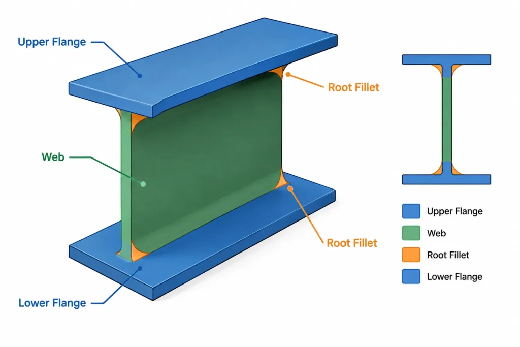
UB identifies the profile as a universal beam, an I-shaped hot-rolled steel section with two flanges connected by a web.
Is the designation the same as the exact beam dimensions?
No. The designation identifies the profile, while the source data provides the detailed dimensions. Use the individual listed values when checking or constructing CAD geometry.
Why is the root fillet radius relevant?
The root fillet forms the curved transition between the web and flange. It can influence clearances for plates, cuts, weld access, fitted parts, and other connection geometry located near the web-to-flange junction.
What does the sectional area describe?
It is the cross-sectional area of steel through the profile. It should not be confused with the beam’s exterior surface area or with an area enclosed by the overall depth and width.
Can the DWG be used directly in a fabrication drawing?
It should first be checked for units, scale, section identity, geometry, origin, and compatibility with the project’s CAD standards. Fabrication use also requires confirmation against the governing project documents and applicable technical requirements.
Does the listed unit weight include connections or coatings?
No. The rolled-section value describes the beam profile per unit length. Attached plates, bolts, weld metal, coatings, and other additions must be considered separately where relevant.