Structural steel section views reveal geometry that plans and elevations cannot show clearly. A well-placed section can explain member orientation, plate position, connection depth, bolt arrangement, and the relationship between adjacent components. A poorly coordinated section can do the opposite, especially when its viewing direction, cut location, or relationship to the parent view is unclear.
For drafters, designers, checkers, and fabricators, the important question is not simply whether a section exists. The section must communicate exactly where the assembly is cut, which way the viewer is looking, and which geometry controls fabrication or erection.
What a structural steel section view represents
A section view is a projected view created by imagining that a cutting plane passes through an object or assembly. Material in front of the cutting plane is conceptually removed so that the viewer can see the cut geometry and the components beyond it.
In structural steel drawings, sections are commonly used to show:
- The orientation of W-shapes, channels, angles, tees, and HSS members.
- The position of connection plates relative to webs and flanges.
- Bolt rows that overlap or appear edge-on in another view.
- Stiffeners, seats, clip angles, cap plates, and base plates.
- Clearances between connected members.
- Offsets, eccentricities, and elevations within an assembly.
- Weld locations that cannot be identified unambiguously in plan or elevation.
A section is therefore more than an illustration. It is a geometric projection tied to a defined cutting plane and viewing direction.
Cutting plane location and viewing direction
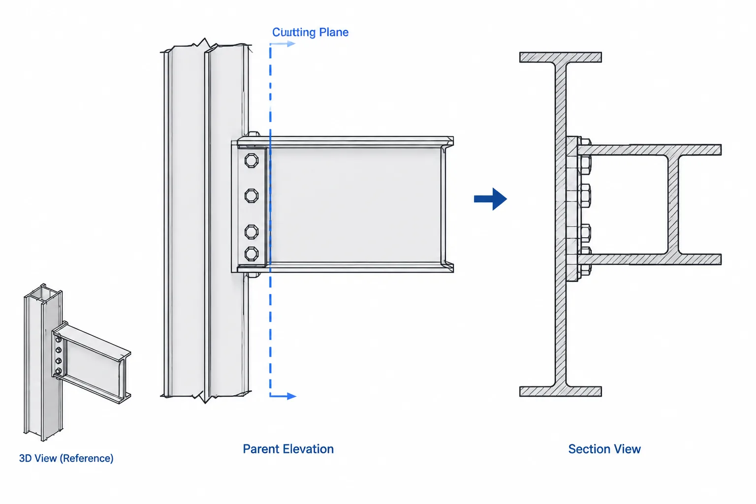
The cutting-plane line identifies where the parent view is being cut. Arrowheads indicate the direction in which the resulting section is viewed. Both pieces of information are necessary. A line without a clear viewing direction can produce a plausible but reversed interpretation.
For example, a section through a beam-to-column connection may show the beam web, connection plates, and column flange. Looking from the opposite direction could reverse near-side and far-side plates, shift an eccentric component to the other side of the web, or make a left-hand assembly appear right-hand.
The cutting plane should pass through the features the section is intended to explain. If the purpose is to show a bolt group, the cut should intersect or clearly relate to that bolt group. If the purpose is to show a stiffener pair, the cut and resulting view should make the plate positions evident.
Straight and offset cutting planes
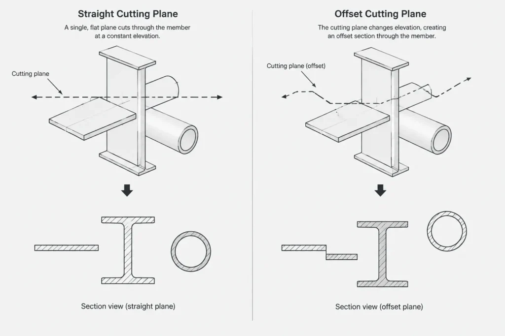
A straight cutting plane lies along one continuous line. It is usually the clearest choice when all relevant features align.
An offset cutting plane changes direction so that several important features can appear in one section. This can be useful when holes, plates, or members do not share a common plane. However, an offset section must not imply that separated features actually lie on the same straight line. The bends in the cutting-plane path should be visible in the parent view, and the resulting section should be arranged according to the project’s drafting conventions.
Section view, detail view, and auxiliary view
These view types solve different drawing problems and should not be treated as interchangeable.
| View type | Primary purpose | Key reference |
|---|---|---|
| Section view | Reveals internal or intersected geometry by cutting through an assembly | Cutting plane and viewing direction |
| Detail view | Enlarges a selected area so that dimensions, welds, holes, or notes can be shown clearly | Detail boundary or source callout |
| Auxiliary view | Shows the true shape of a feature located on an inclined or skewed plane | Projection perpendicular to the feature plane |
A section may also be enlarged, but enlargement alone does not make a view a section. Similarly, a detail may show hidden components without representing a physical cut. Understanding the view type helps the reader determine whether apparent distances are true dimensions, projected dimensions, or merely graphic spacing.
How common steel shapes appear in section
W-shapes and other I-sections
A transverse section through a W-shape exposes both flanges and the web. This view is useful for confirming flange direction, web alignment, plate attachment, and member rotation. Rolled fillets may be represented according to drawing scale and purpose, but simplified graphics should not be used to establish fabrication clearances near the web-to-flange region.
HSS members
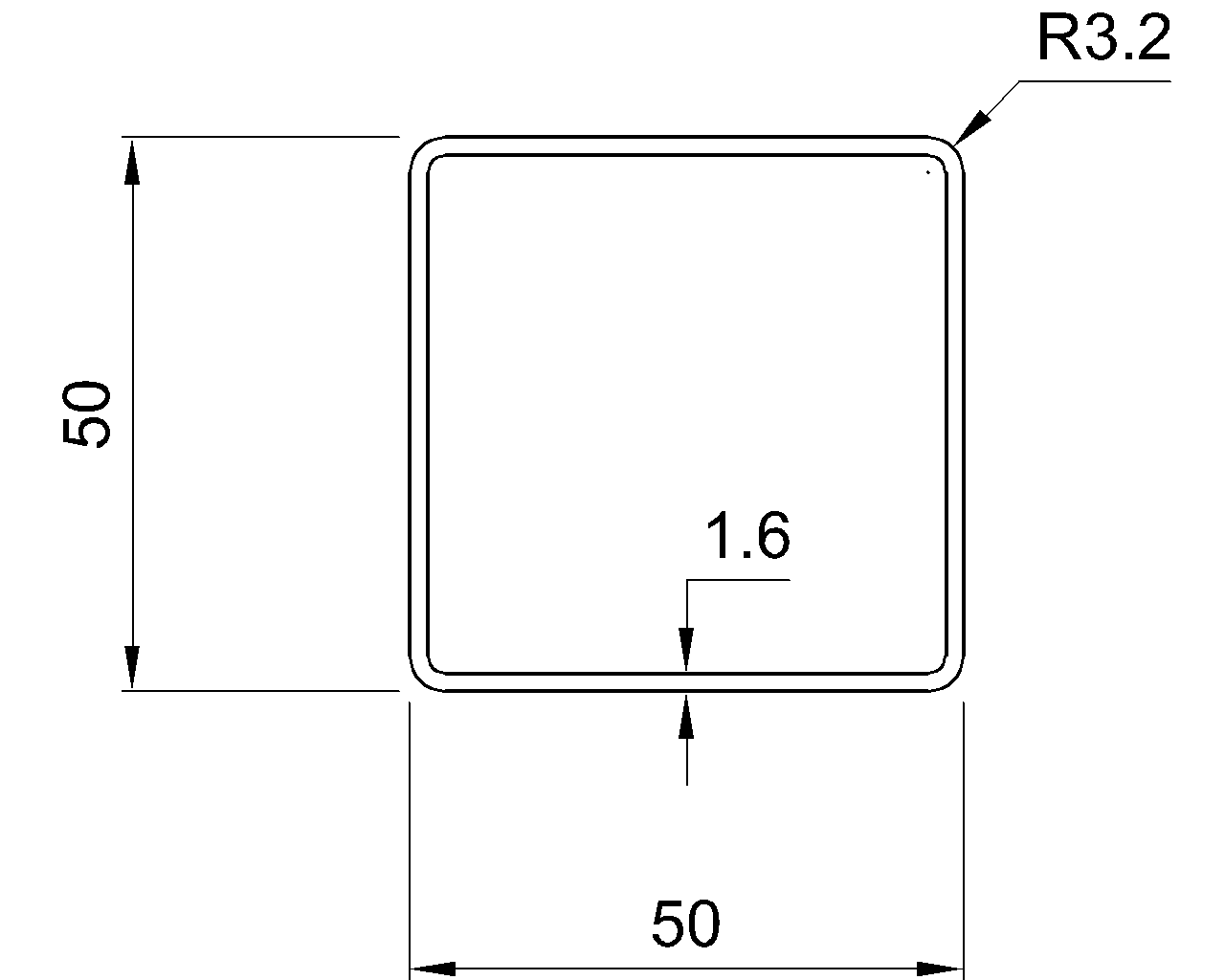
A cut through rectangular, square, or round HSS reveals the enclosed void and wall arrangement. The outline should communicate the section family and orientation without implying that simplified CAD corner geometry is a substitute for verified product dimensions. When a plate, knife plate, diaphragm, or insert enters the HSS, the section should distinguish the inserted component from the HSS wall.
Channels, angles, and tees
Open shapes require particular attention to orientation. A channel section should make its open side and flange toes evident. An angle section should show which leg is vertical, which leg is horizontal, and which leg is connected. A structural tee section should establish whether its stem and flange orientation matches the parent view and member callout.
These shapes can be easy to reverse when a section arrow is overlooked. Labels and dimensions should reinforce the geometry rather than compensate for an ambiguous view.
Cut material, background geometry, and hatching
Geometry intersected by the cutting plane is typically emphasized relative to components seen beyond the cut. Hatching or section lining can help identify cut material, but its use should follow the drawing set’s established graphic conventions.
Adjacent steel parts may use different hatch directions or spacing so their boundaries remain visible. In crowded connection sections, excessive hatching can obscure bolt holes, weld symbols, and plate edges. Selective hatching, heavier cut outlines, or restrained poche may communicate the assembly more effectively.
Background geometry should remain subordinate. If every edge has equal visual weight, readers may struggle to distinguish the cut face from components beyond it. Hidden lines should also be used selectively; including every concealed edge can make a small steel connection section difficult to interpret.
Dimensioning a steel section
A section view should receive dimensions that are most clearly and directly shown in that projection. Typical examples include plate thickness, member depth orientation, spacing across a web, projection from a flange, or an offset between component centerlines.
Avoid repeating controlling dimensions from another view unless repetition is intentional and coordinated. Duplicate controlling dimensions can become contradictory after revisions. When a value is repeated only for convenience, the drawing should make its status clear under the project’s dimensioning practice.
Dimensions should reference stable geometric features, such as centerlines, faces of steel, work points, or plate edges. The selected datum must match the design and fabrication intent. A dimension from an idealized CAD centerline is not automatically interchangeable with a dimension from an actual face of steel.
Section identification and sheet coordination
Each section should have a unique identifier within the drawing system. The source callout should direct the reader to the section, while the section title should direct the reader back to its origin when the drawing format requires that relationship.
Before issuing a drawing, verify that:
- The cutting-plane label matches the section title.
- The section appears on the referenced sheet or view location.
- The arrow direction agrees with the displayed orientation.
- Member marks and plate marks match the parent view.
- Near-side and far-side components have not been reversed.
- Revision changes are reflected in both the section and its source view.
Broken references are particularly common when views are copied between sheets or when CAD layouts are reorganized late in production.
A practical CAD workflow
- Define the communication goal. Decide whether the section must show orientation, connection depth, fit-up, weld access, bolt placement, or another specific condition.
- Select the parent view. Place the cutting-plane callout where the cut location can be understood without guesswork.
- Establish the viewing direction. Choose the direction that minimizes hidden geometry and preserves a logical relationship with nearby views.
- Project controlling geometry. Carry across member centerlines, faces, plate edges, and relevant work points before adding small details.
- Differentiate cut and uncut objects. Apply lineweights, hatching, and hidden lines consistently.
- Add dimensions and connection information. Include only information best communicated in the section and coordinate it with other views.
- Check the view against the model or assembly. Confirm shape orientation, offsets, component side, and member direction.
- Audit references after revisions. Recheck labels, sheet references, marks, and callout locations whenever views move or geometry changes.
Common section-view errors
- Reversed viewing direction: The section is drawn as if viewed opposite the arrows.
- Cut plane misses the feature: The section shows a bolt row or plate that the indicated plane does not intersect.
- Unclear depth: Components beyond the cut are drawn as though they are cut at the same plane.
- Overloaded graphics: Hatching, hidden lines, dimensions, and weld symbols compete for the same space.
- Uncoordinated duplicate dimensions: The section conflicts with a plan, elevation, or detail.
- Mirrored open shapes: Channels and angles face the wrong direction relative to the source view.
- Detached section: The view appears correct by itself but no longer matches its parent callout after revisions.
Use sections as coordinated projections
The clearest structural steel section views are built from a deliberate cut location, an unmistakable viewing direction, and a controlled hierarchy of lines and information. They should confirm the geometry shown elsewhere rather than create a separate interpretation of the assembly.
CAD automation and model-generated sections can accelerate drawing production, but they do not eliminate the need for technical review. Every section should still be checked for orientation, visibility, references, dimension control, and consistency with the intended steel assembly.