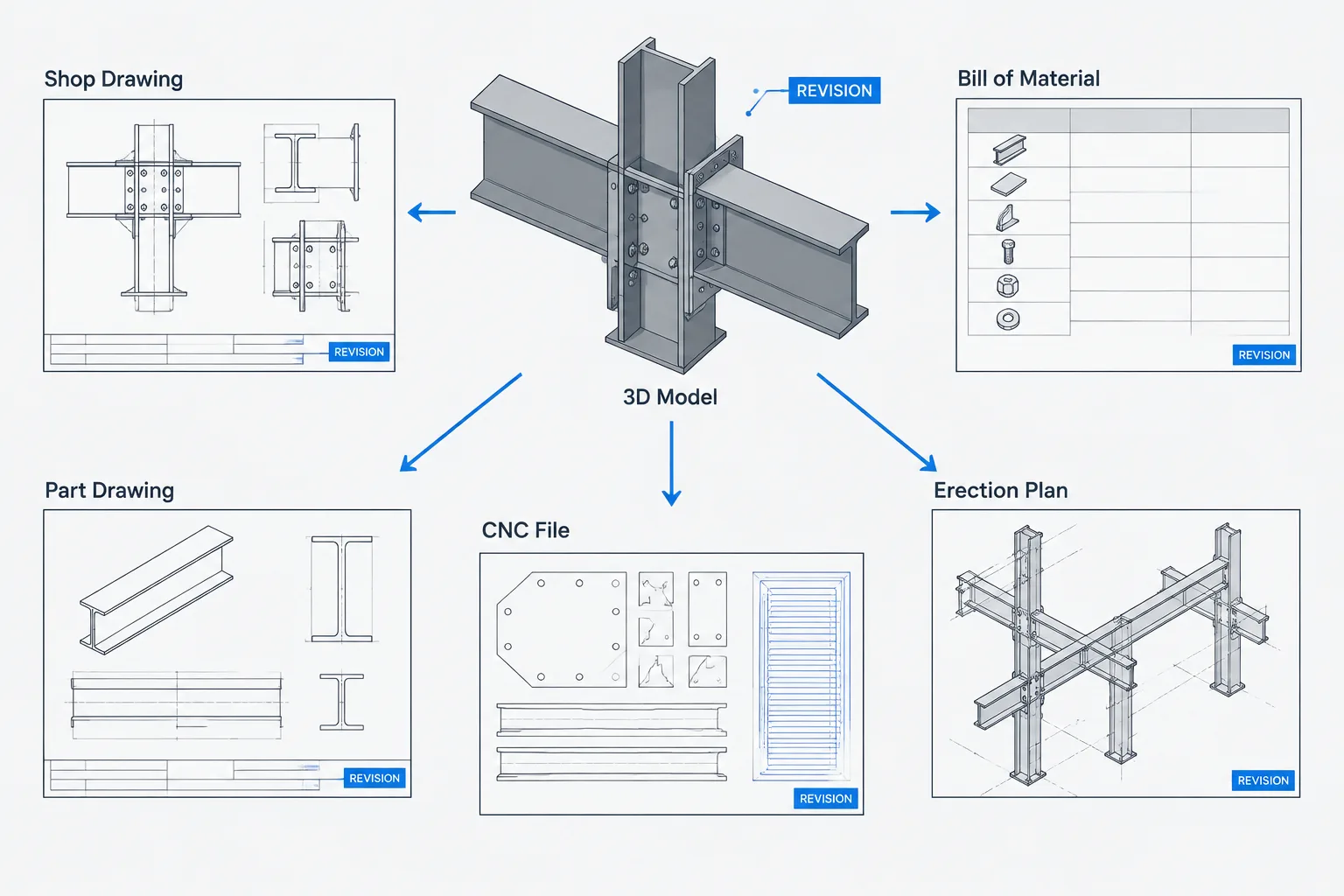
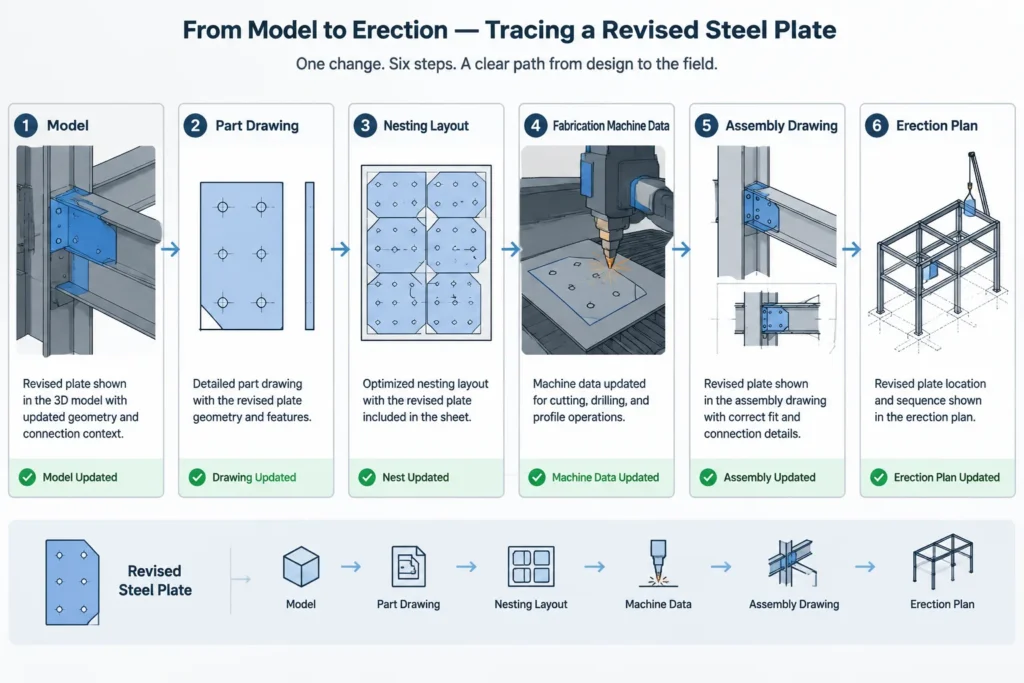
A structural steel revision rarely affects only one drawing. Moving a hole, changing a plate, revising a member length, or substituting a shape can propagate through the model, assembly details, part drawings, bills of material, erection plans, and machine data. If one output remains unchanged, the fabrication package may contain conflicting instructions.
Effective structural steel revision control is therefore more than placing a cloud around edited geometry. It is a coordinated process for identifying what changed, tracing every affected deliverable, and making sure the shop and field are using compatible information.
Why steel revisions spread across multiple documents
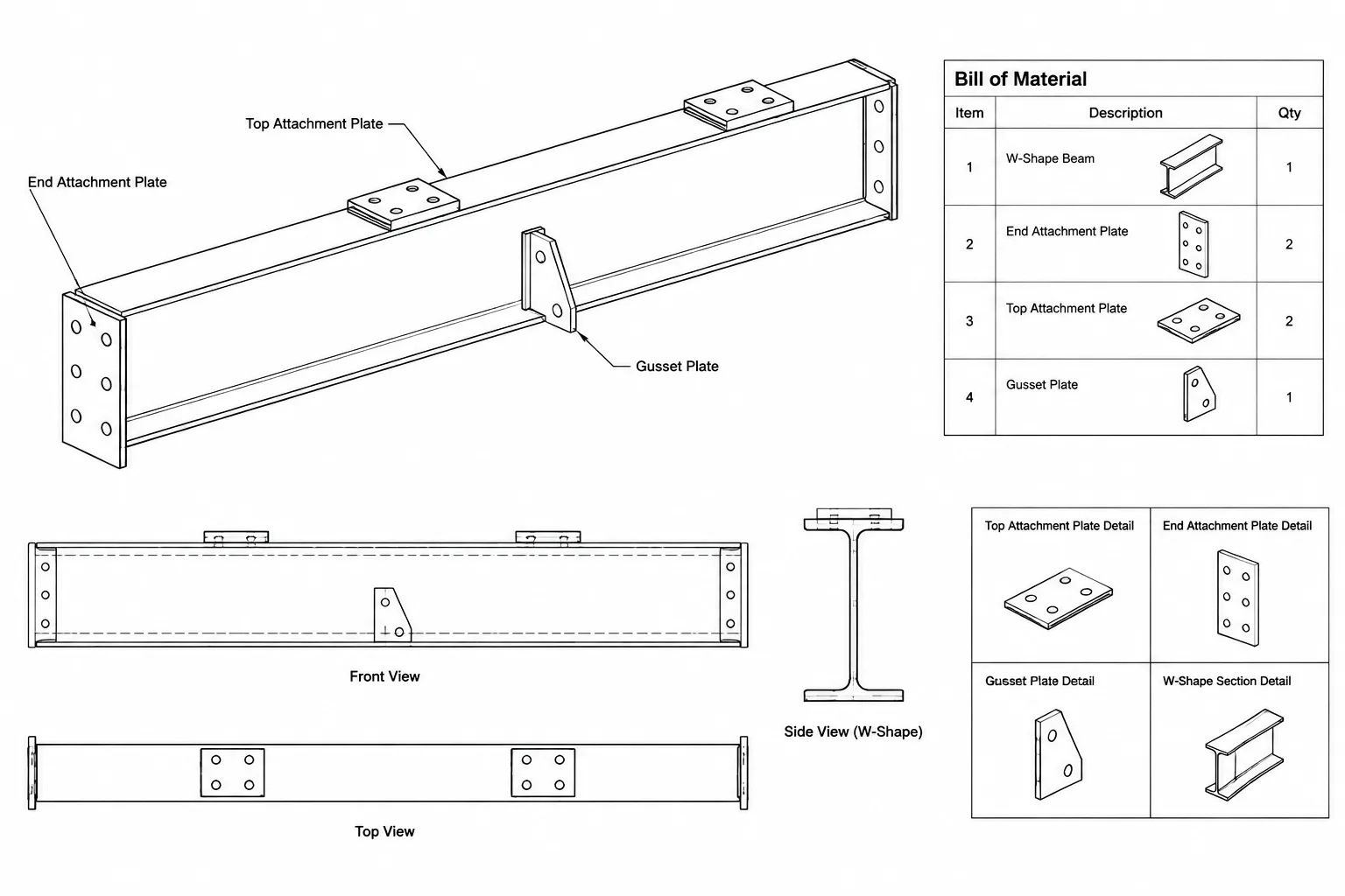
Structural steel information is interconnected. An assembly drawing may show a beam and its connection plates, while separate part drawings define those plates. The same parts may also appear in a bill of material, purchasing list, nesting file, CNC file, and erection plan.
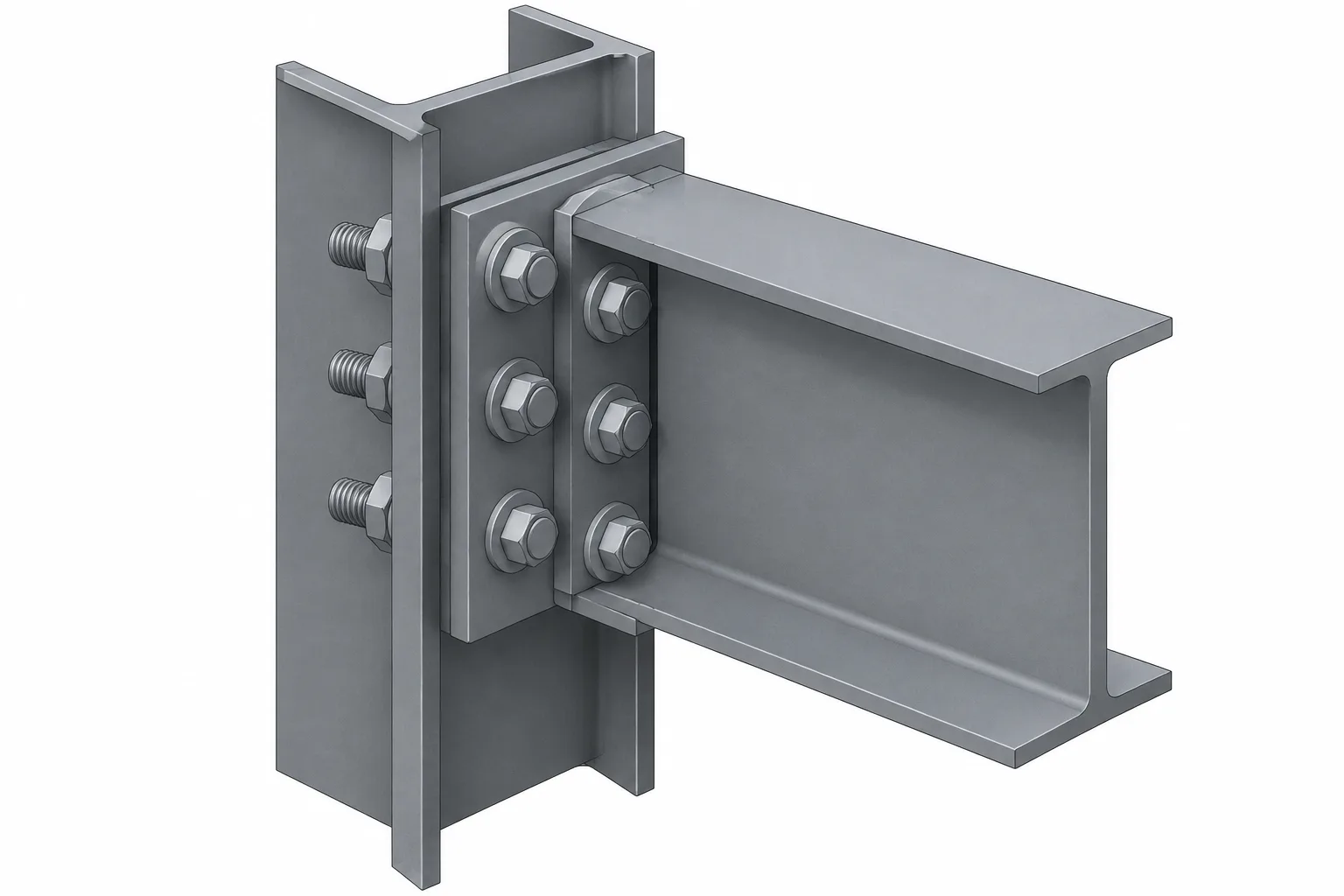
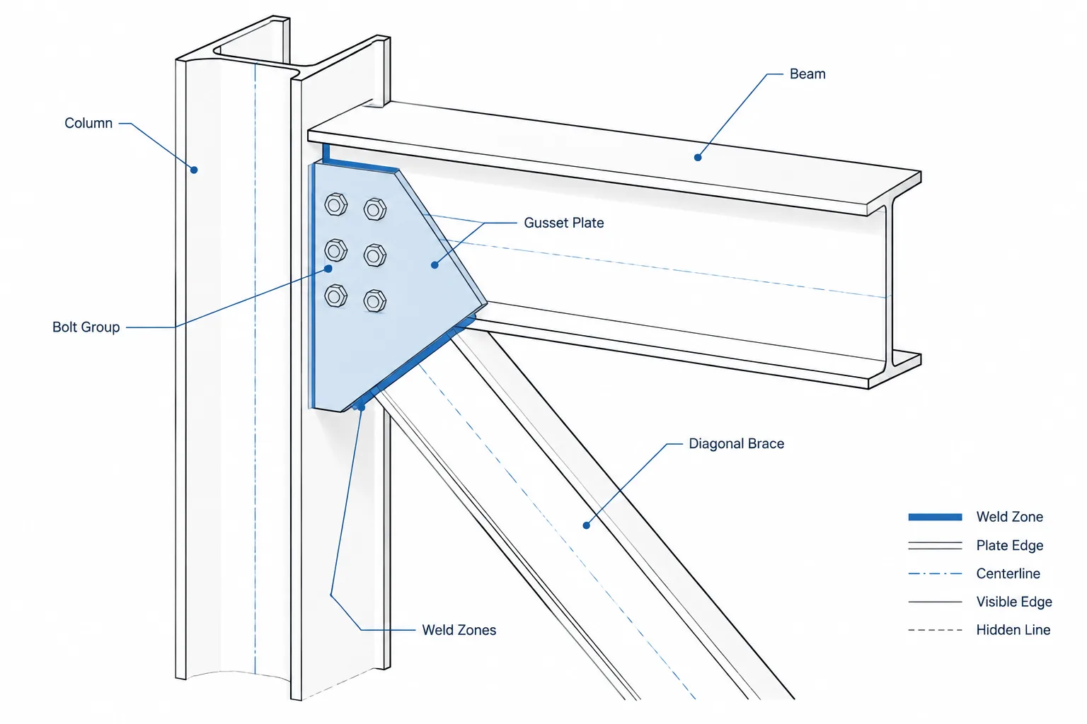
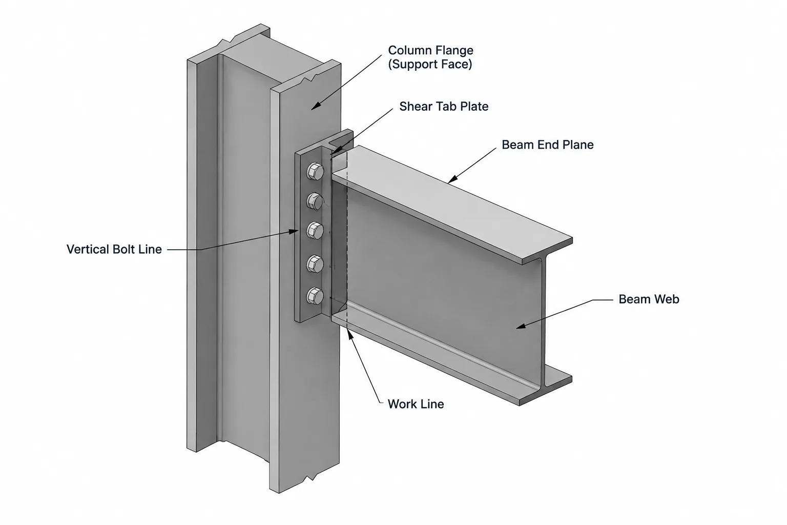
Consider a beam-end connection that is moved along the member. The visible drawing change may appear to be a simple hole relocation, but it can also affect:
- Hole coordinates in the beam web
- The detailed length or location of an attached plate
- Connection dimensions on the assembly drawing
- Machine data generated for the beam or plate
- Overall assembly weight or coating area
- Interference checks against adjacent members
- Erection geometry and field fit-up
The revision process must follow the information, not merely the sheet on which the change was first noticed.
Four categories of revision
Classifying a change helps determine how far the review should extend. The categories below are practical workflow descriptions rather than contractual definitions.
Geometry revisions
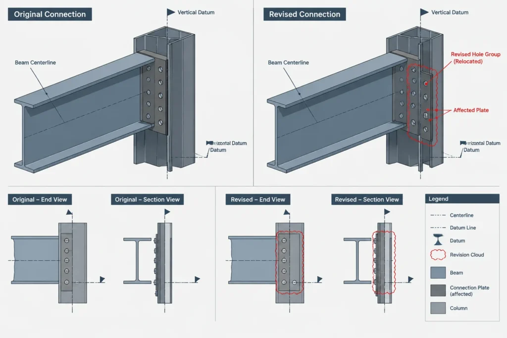
Geometry revisions alter the physical form or location of steel. Examples include member length changes, relocated holes, revised copes, changed plate outlines, different bevels, and modified connection offsets. These changes deserve careful review because they can invalidate existing shop dimensions and fabrication data.
Material or shape revisions
A change in shape designation, plate thickness, material callout, or component type may affect purchasing, weight, fit, connection design, and fabrication. A nominally similar replacement should not be treated as interchangeable without checking actual dimensions and section properties.
Identification revisions
These include changed piece marks, assembly marks, sheet references, sequence labels, or shipping identifiers. The physical steel may be unchanged, but a mark revision can still disrupt material tracking and erection if it is not propagated consistently.
Presentation-only revisions
Some edits improve clarity without changing fabrication intent, such as moving a note, adjusting a view, or correcting noncontrolling text. Even these changes should be classified deliberately. What appears graphical may conceal a changed dimension, leader target, or reference.
Revision status should be separate from fabrication status
A drawing can be revised without the corresponding material being in the same production state. One affected piece may exist only in a model, another may already be cut, and another may have been shipped. A revision log that records only sheet status cannot answer whether physical work has begun.
Useful fabrication-status distinctions may include:
- Not released
- Released but not started
- Material ordered
- Cut or drilled
- Assembled
- Coated
- Shipped
- Erected
The exact status names depend on the fabricator’s workflow. The important point is to connect revision review with the real production condition of each affected item. A model correction made before release has different consequences from the same correction made after fabrication.
Building an impact check
An impact check is a disciplined search for every output derived from the changed information. It can be maintained as a checklist, database record, or controlled project note.
| Changed item | Outputs to review | Typical coordination question |
|---|---|---|
| Member size | Model, assembly drawing, BOM, purchasing data, erection plan | Do dimensions, weight, fit, and connection assumptions still agree? |
| Member length or end location | Assembly detail, erection geometry, end cuts, CNC data | Are work points, setbacks, cut length, and hole locations still coordinated? |
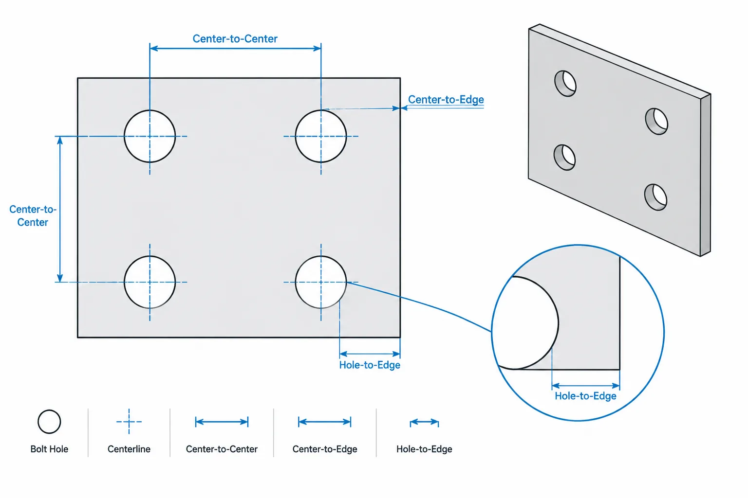
| Hole pattern | Connected parts, bolts, part drawings, CNC files | Do mating holes share the same datum, orientation, and revision? |
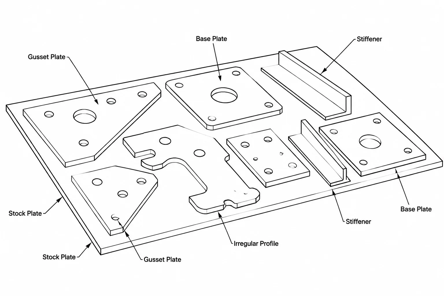
| Plate geometry | Part drawing, nesting, BOM, assembly view | Has the plate been renested or previously cut? |
| Piece or assembly mark | All drawings, lists, labels, shipping records | Can the old and new identities be confused? |
| Connection design information | Calculations, design sketches, model, details, affected members | Has the revision been confirmed by the responsible design party? |
This review should move in both directions. If a beam changes, examine attached parts. If a plate changes, identify every assembly that uses that part. Repeated parts require particular care because one part mark may appear in several assemblies.
Piece marks and revision strategy
Whether a changed item keeps its mark or receives a new one depends on project and fabrication procedures. The decision should communicate manufacturing interchangeability clearly.
If two pieces share a mark, the shop generally expects them to be physically interchangeable. Keeping the same mark for pieces with different hole patterns, lengths, or material creates a serious tracking risk. Conversely, assigning new marks for every harmless annotation change can create unnecessary records and confusion.
Before deciding, ask:
- Does the physical piece change?
- Can revised and unrevised pieces still be used in the same location?
- Has any quantity already been fabricated?
- Does the change apply to every instance of the mark?
- Will the new identity remain coordinated with labels, loads, and erection plans?
Mark changes should be intentional and documented rather than produced automatically by renumbering software without review.
Revision clouds are locators, not complete instructions
A revision cloud helps a reader find an edited area, but it does not explain the full technical effect. The associated revision description should identify the nature of the change in useful terms. A vague note such as “revised” forces the reader to compare drawing versions visually.
A stronger description identifies the affected element and action, such as a revised end connection, updated member length, or relocated hole group. It should remain concise without implying approval beyond the actual review performed.
Cloud boundaries also require judgment. A cloud around one changed dimension may be too narrow if nearby geometry and notes were updated. A cloud around an entire sheet may be too broad to guide the shop efficiently. The marked area should help a technical reader locate all relevant edits without obscuring what is unchanged.
Managing CNC and other fabrication data
Machine files can remain usable even when their source drawing is obsolete, which makes them especially important in revision control. Renaming or superseding a drawing does not automatically prevent an older fabrication file from reaching equipment.
After a physical change, verify that:
- The machine file was regenerated from the correct model state
- The file identity matches the current part or assembly mark
- Obsolete files are removed from active production locations
- Hole, cut, contour, and orientation data match the current drawing
- The shop knows whether an existing piece requires rework or replacement
Similar control applies to plate nesting, saw lists, cut lists, labels, and automated reports. Regeneration alone is not enough; the revised output should be checked against the intended change.
CAD model practices that support reliable revisions
A well-structured model makes changes easier to trace. Members and detail parts should have stable identities, clear relationships, and consistent local orientation. Dimensions should derive from intended datums rather than incidental snap points or display geometry.
Helpful model practices include:
- Using deliberate work points and reference planes
- Keeping piece and assembly properties synchronized with drawings
- Reviewing dependent views after model changes
- Checking mirrored or repeated components separately
- Comparing current and previous model states when possible
- Recording why a change was made, not only who edited the file
Automatic drawing updates can reduce manual effort, but they do not replace technical review. A view may update while an annotation, section cut, manually entered note, or external fabrication file remains stale.
A practical closeout sequence
Before issuing a revised steel package, use a repeatable closeout sequence:
- Confirm the source and authorization for the change.
- Identify affected members, parts, and repeated marks.
- Update the controlled model or drawing source.
- Regenerate dependent views, lists, and fabrication outputs.
- Compare revised information with the previous issue.
- Check mating components and neighboring assemblies.
- Determine the fabrication status of affected material.
- Assign appropriate drawing and item revision identification.
- Remove or segregate superseded files from active use.
- Communicate rework, replacement, or field consequences to the appropriate parties.
The goal is not merely to publish a newer drawing. It is to leave one coherent set of instructions for design coordination, fabrication, delivery, and erection. Good structural steel revision control makes the current intent easy to identify and makes obsolete information difficult to use accidentally.