A structural steel member can have several valid lengths, each describing a different part of the design, detailing, or fabrication workflow. The distance between work points may establish the structural layout, while the physical member stops short of those points because of connection geometry. A fabricator may use a cut length for production and an ordered length for material planning. Treating these values as interchangeable can create fit-up problems, quantity errors, and confusing shop drawings.
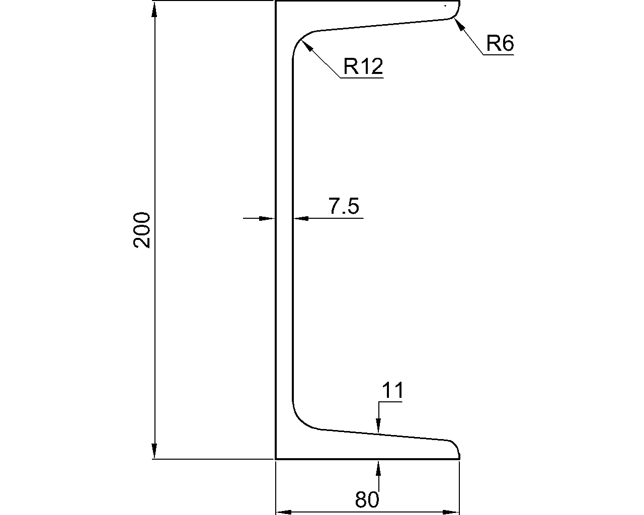
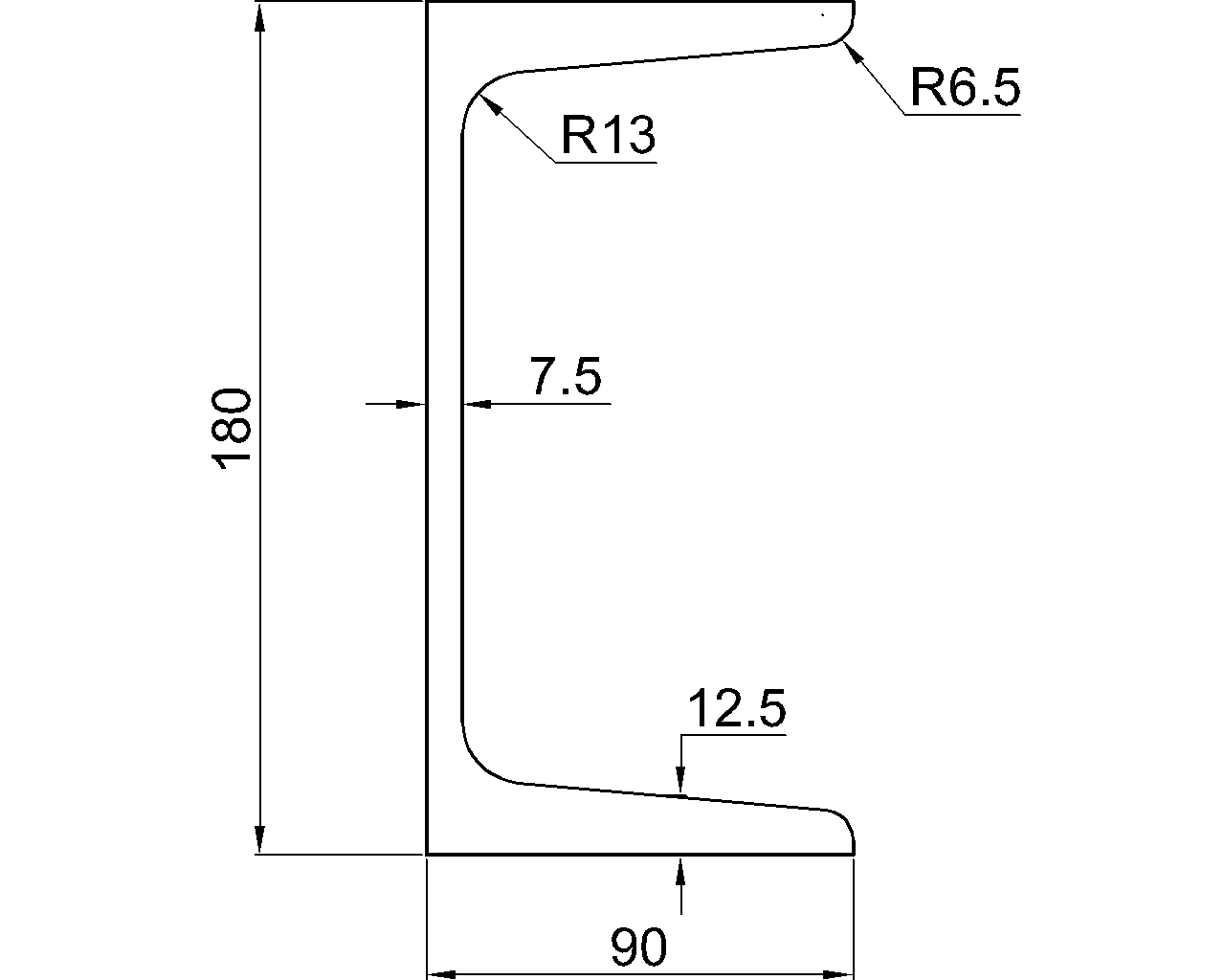
The key is to identify what each length measures, where its endpoints are located, and which value controls the physical part. Shape-table dimensions help define the cross-section, but they do not determine the longitudinal limits of a specific beam, column, brace, channel, angle, tee, or HSS member.
Why one member may have several lengths
Structural framing is commonly laid out with grids, centerlines, elevations, and work points. These references describe where members meet conceptually. Real steel, however, needs space for plates, welds, bolts, bearing conditions, erection clearances, and adjacent members.
As a result, a member shown between two theoretical intersections may have a shorter physical length. Conversely, an extended end, bearing projection, splice allowance, or fabrication operation can make a production dimension longer than a simple centerline distance suggests.
The terminology used by individual companies can vary. Drawings and fabrication systems should therefore define their conventions rather than relying on a label alone.
Common structural steel length terms
| Length term | Typical meaning | Primary use |
|---|---|---|
| Work-point length | Distance between theoretical layout points associated with the member | Structural geometry, framing layout, and model coordination |
| Centerline length | Distance measured along the member reference line between stated limits | Plan and elevation layout, analytical models, and conceptual framing |
| Detailed length | Dimension used on the detail to describe the member between clearly identified endpoints | Shop drawing communication and dimensional control |
| Cut length | Physical end-to-end length produced by a cutting operation, subject to the defined end geometry | Fabrication and machine data |
| Ordered length | Length of stock requested or allocated before final processing | Purchasing, nesting, inventory, and material planning |
| Shipping length | Overall length of the shipped member or assembly | Handling, transportation, and erection planning |
These descriptions are practical rather than universal contractual definitions. A shop may use “detail length” and “cut length” for the same value on a square-ended member but distinguish them when end preparation is more complex.
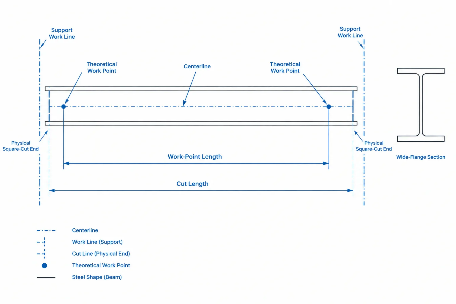
Work-point length describes the framing system
A work point is a theoretical geometric reference. It may occur at a grid intersection, the crossing of member centerlines, a column centerline, a bearing line, or another designated control point. Work points are especially important for braces, sloped framing, trusses, and members framing to skewed supports.
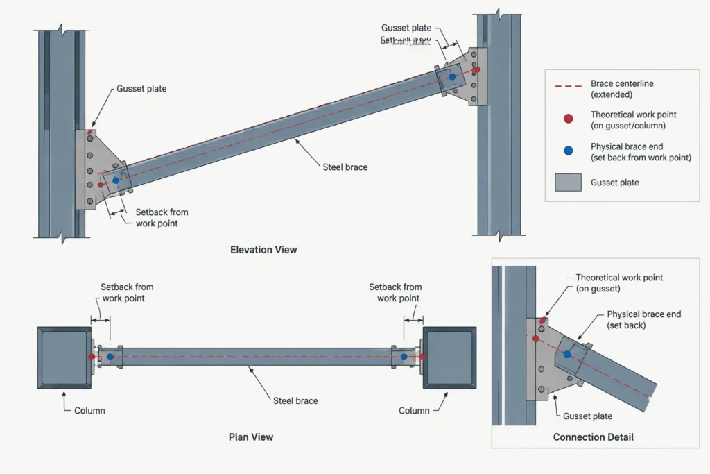
The work-point length is normally measured along the member’s reference axis. It does not automatically equal the physical length of the steel. If a beam frames to a column with a connection plate between them, the beam end may be offset from the column work line. A brace centerline may intersect a gusset work point even though the brace terminates well before the intersection.
Work-point dimensions are valuable because they preserve design geometry when connection configurations change. They should not be sent directly to fabrication as physical cut dimensions unless the end offsets and conventions have been resolved.
Detailed length must have identifiable endpoints
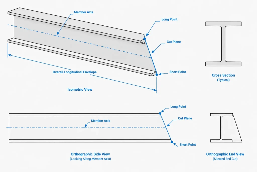
A useful detailed length answers two questions: where does the measurement begin, and where does it end? Possible endpoints include square-cut ends, long points of skewed cuts, short points, plate faces, bearing lines, or theoretical intersections.
For a member with square ends perpendicular to its axis, the detailed length may be straightforward. Ambiguity increases when a member has:
- skewed or sloped end cuts;
- top-flange or bottom-flange extensions;
- beam copes or flange notches;
- mitered HSS ends;
- end plates projecting beyond the main shape;
- bearing seats or attached connection material;
- different termination planes for the web and flanges.
In these cases, a single overall dimension may not fully define the part. The drawing may also need end-cut angles, setbacks, point-of-work dimensions, or separate dimensions to critical end features.
Cut length depends on the end geometry
Cut length generally refers to the physical length of the main shape after its ends are cut. The term is simple for a beam with two square cuts, but less precise for angled cuts because one end can have several measurable longitudinal extents.
For a skewed cut through a wide-flange member, the flange tips do not necessarily terminate at the same station along the member axis. For a mitered rectangular HSS, an outside corner may define the longest point while another corner defines the shortest. A cut list must make clear whether its reported value represents an axial datum, an overall bounding length, or a specific physical corner.
Automated equipment may also require geometry beyond a single cut-length field. Machine exports should be checked for member-axis direction, start and end identification, section rotation, cut-plane orientation, and units.
Ordered length is a material-planning value
Ordered length concerns the stock needed to produce the finished part. It may differ from the final cut length because fabrication requires room for cutting, end preparation, sequencing, or other shop considerations. Multiple parts may also be nested within one stock length.
A bill of material should distinguish the finished member requirement from the stock or procurement quantity when both are shown. Otherwise, users may mistake purchasing information for the final geometry required in the structure.
Ordered length should not be inferred by adding an informal allowance to every part. Stock planning depends on the fabricator’s process, available material, cutting method, nesting strategy, and project requirements.
Length deductions at member ends
A common detailing workflow starts with the distance between work points and applies end deductions or extensions to obtain the physical member length. Conceptually:
Physical axial length = work-point distance − start setback − end setback + applicable extensions
This relationship is only a framework. The signs and measured directions depend on the adopted coordinate system and endpoint definitions. For sloped or skewed members, deductions measured horizontally or vertically cannot be subtracted directly from a true member-axis length without resolving the geometry.
Each end condition should be evaluated independently. Similar-looking beam ends may have different setbacks because they frame to different support faces, connection plates, or column orientations.
CAD and model checks
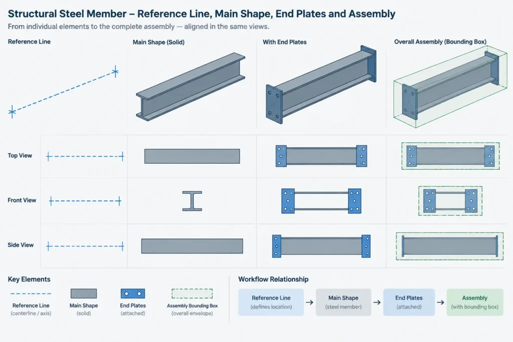
In CAD and three-dimensional detailing, the member reference line and the modeled solid should be checked separately. A correct centerline does not guarantee correct physical ends, and a visually acceptable solid does not prove that its work points remain aligned with the structural layout.
Recommended verification sequence
- Confirm the member start point, end point, and local longitudinal axis.
- Identify whether the reference line represents a centroidal axis, top-of-steel line, face line, or company-specific insertion line.
- Compare work-point coordinates with the structural framing references.
- Measure the modeled solid between the intended physical endpoints.
- Inspect skewed cuts in a view normal to the cut plane when practical.
- Check whether attached plates control the assembly’s overall length.
- Compare drawing dimensions, model data, cut lists, and bills of material.
- Verify units and rounding before transferring data between systems.
Bounding-box dimensions can help with shipping and clash reviews, but they are not always valid fabrication lengths. A rotated or sloped member can have a global bounding-box length substantially different from its true axial length.
Beams, braces, columns, and assemblies need different checks
Beams
Check end setbacks from supporting members, bearing requirements, connection plate locations, copes, and skewed end cuts. Determine whether the stated length runs between web end planes, flange extremities, or work lines.
Braces
Keep work-point geometry separate from the physical brace ends. Gusset interfaces, end connections, and member slopes can create substantial differences between work-point length and cut length.
Columns
Distinguish shaft length from assembly length. Base plates, cap plates, splice plates, and milled or prepared end surfaces may control different dimensions. Elevation references also need to identify whether they apply to the column end, an attached plate, or a theoretical level.
Shop assemblies
An assembly’s overall length may be governed by attached material rather than the main member. Both the main-shape cut length and the complete assembly envelope can be necessary for fabrication, shipping, and erection.
A practical drawing checklist
- State the dimensional convention used for member lengths.
- Show work points when they are necessary to understand the framing geometry.
- Define whether end dimensions locate long points, short points, centerline intersections, or cut planes.
- Do not rely on scaled measurement from a drawing.
- Coordinate member lengths with connection details and support faces.
- Use enough dimensions to define compound, skewed, or sloped cuts.
- Separate main-member length from overall assembly length where needed.
- Recheck schedules and material lists after connection or framing revisions.
The controlling length must be explicit
There is no single structural steel member length that serves every purpose. Work-point length controls theoretical framing geometry, detailed and cut lengths define the physical part, ordered length supports material planning, and assembly length may control handling or erection.
Clear endpoint definitions are more reliable than terminology alone. Before using any length from a model, drawing, schedule, or data export, confirm what was measured, along which axis, and between which references. Final dimensions and fabrication information must be verified against the project documents, connection requirements, and the responsible fabricator’s established workflow.