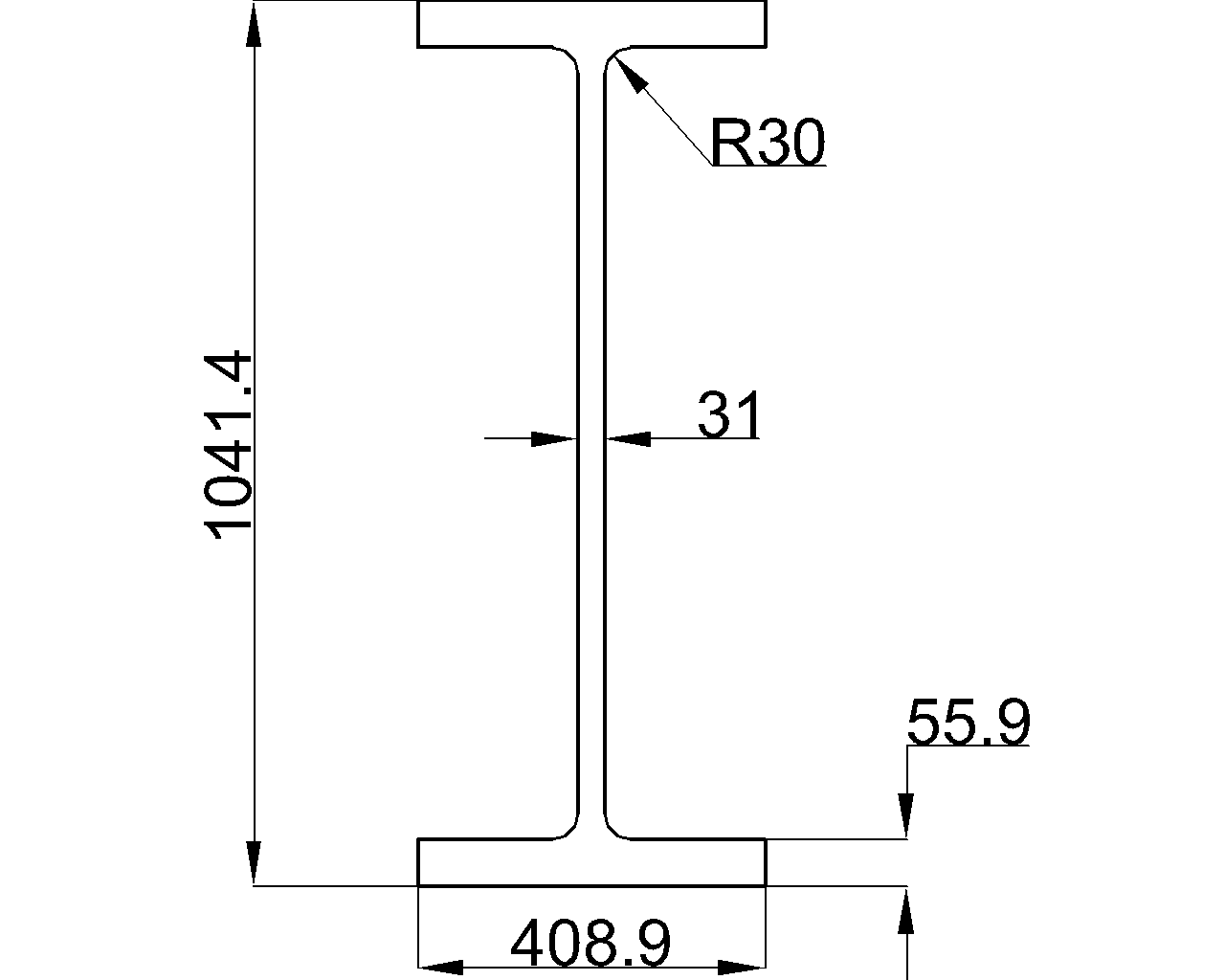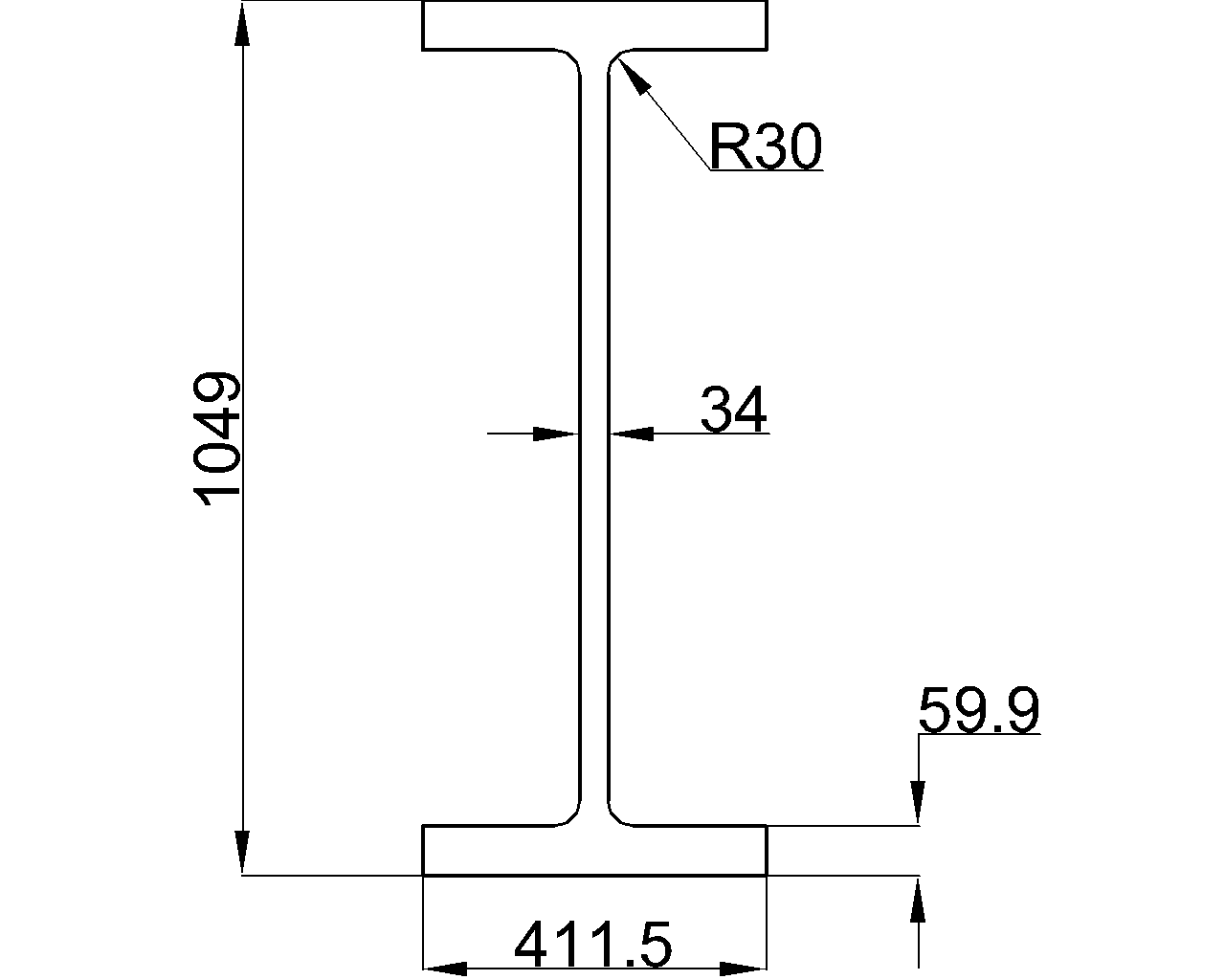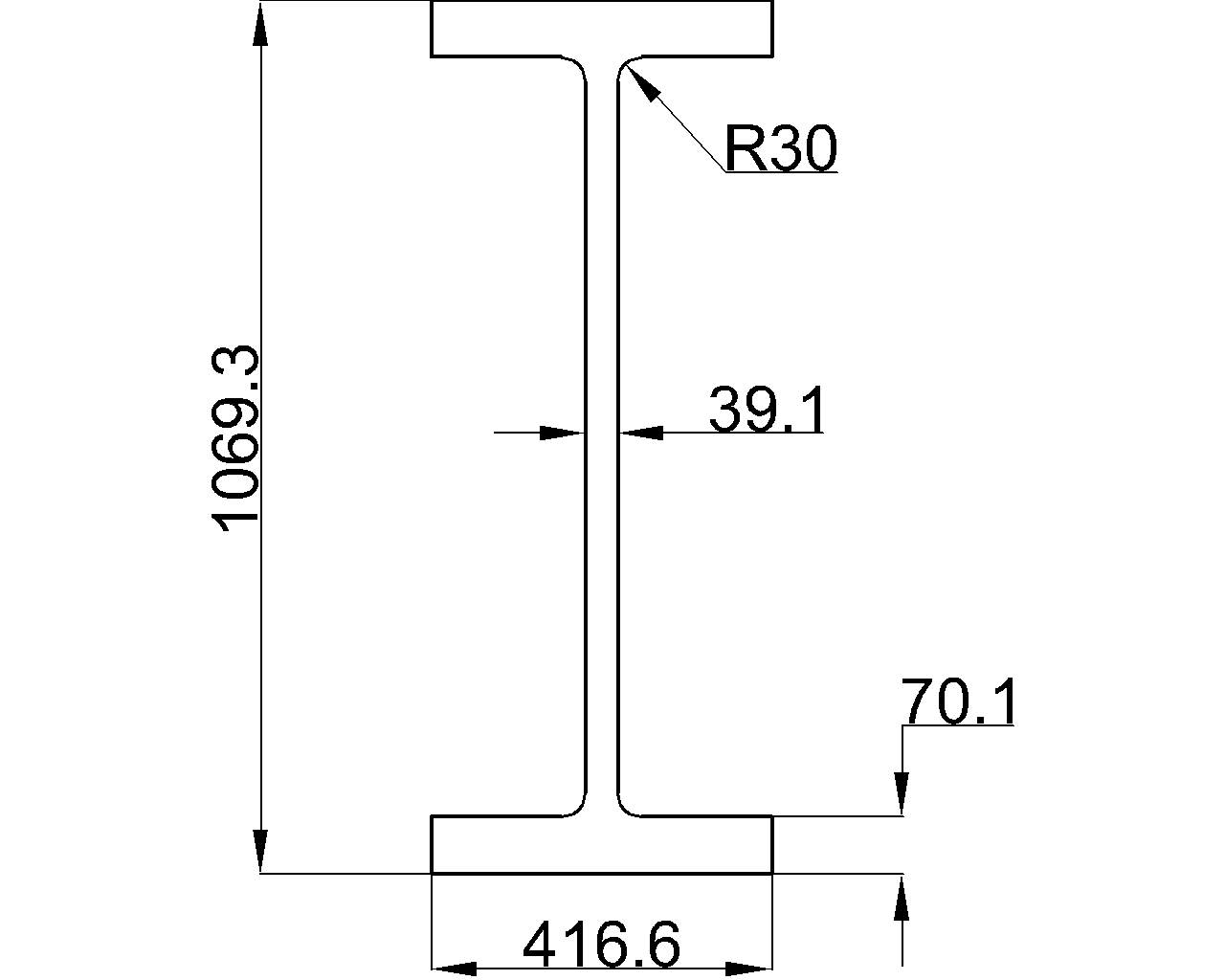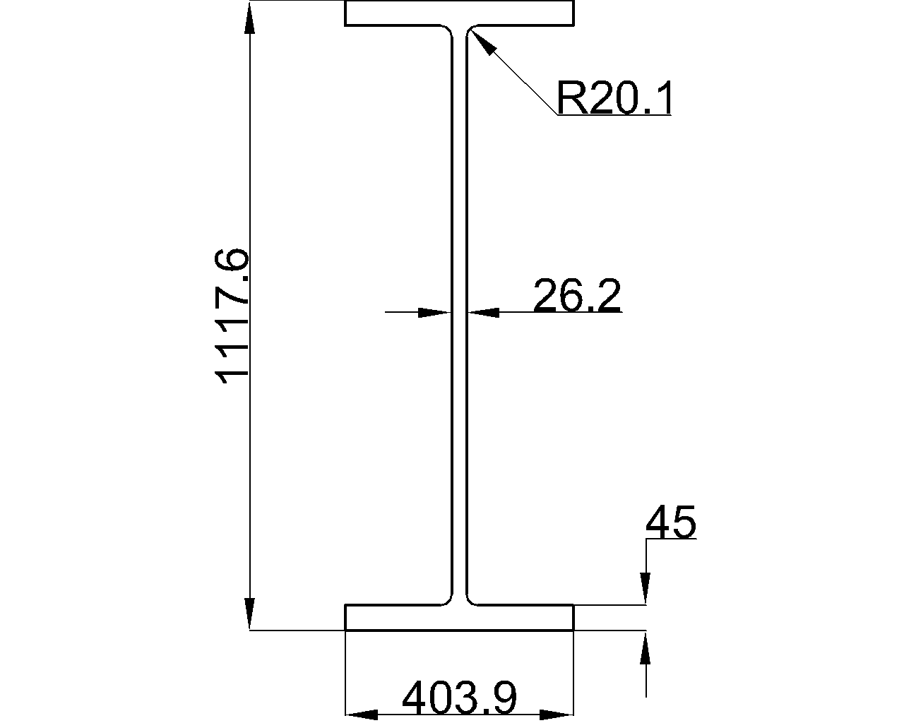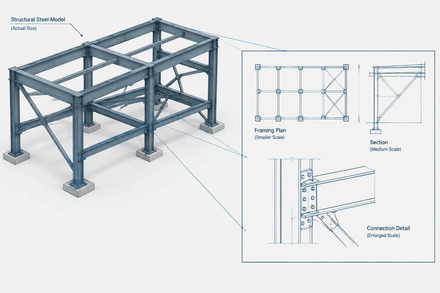
Structural steel drawing scale affects far more than how large a view appears on a sheet. It influences line clarity, annotation, detail selection, PDF review, and the reliability of measurements taken from drawings. Scale mistakes can also conceal a larger problem: geometry that was drafted at the wrong size or imported with incompatible units.
A sound workflow separates three ideas that are often confused: the actual size of the steel geometry, the presentation scale of a drawing view, and the accuracy of any measurement taken from a printed or electronic sheet. Understanding that separation helps drafters create dependable documents and helps reviewers recognize when a visual check is useful but not controlling.
Actual Geometry and Presentation Scale Are Different
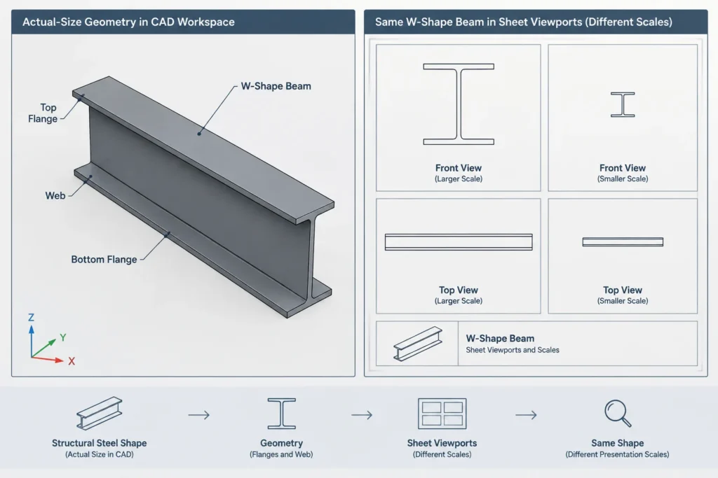
In a typical CAD workflow, structural members, plates, holes, and connection components are modeled or drawn at their intended actual size. A sheet view then reduces or enlarges that geometry so it fits within a plan, elevation, section, or detail.
Changing the presentation scale should not change the underlying member length, plate outline, hole location, or section profile. It changes only how the geometry is displayed on the sheet. If changing a view scale alters actual dimensions, the file may contain scaled objects rather than correctly sized geometry.
This distinction can be summarized as follows:
| Item | What it controls | What it should not control |
|---|---|---|
| Model geometry | Actual member and component size | How large the view appears on a sheet |
| View or viewport scale | Presentation size of the model on the sheet | Actual steel dimensions |
| Annotation settings | Readable text, symbols, leaders, and dimensions | Physical shape geometry |
| Print or PDF settings | Output size and sheet reproduction | Design intent represented by written dimensions |
Scale Does Not Replace Dimensions
A structural steel drawing should communicate controlling geometry through dimensions, elevations, coordinates, notes, and referenced details. Measuring the picture is not a substitute for reading that information.
Even a drawing labeled with a scale may not reproduce at that scale after it has been scanned, resized, inserted into another document, or printed with a fit-to-page option. Electronic viewing can introduce another layer of uncertainty because monitor zoom has no direct relationship to the drawing’s stated scale.
For these reasons, a scaled measurement is best treated as a limited review tool. It may help identify a major discrepancy, such as a member appearing much shorter than its dimension indicates, but it should not establish a fabrication dimension that is absent from the documents.
When a scaled check can be useful
- Comparing the apparent proportions of adjacent members.
- Finding a possible mismatch between a dimension and the drawn geometry.
- Checking whether a detail has been inserted at an obviously incorrect size.
- Reviewing general clearance or congestion before requesting confirmed dimensions.
- Detecting a PDF or plotting problem by comparing a known reference with the output.
When scaling should not control
- Locating bolt holes for fabrication.
- Determining plate length, width, or thickness.
- Establishing edge distance, end distance, gage, or pitch.
- Deriving a beam setback, cope, skew, slope, or connection elevation.
- Selecting a steel shape based only on its drawn outline.
Plans, Elevations, Sections, and Details Need Different Treatment
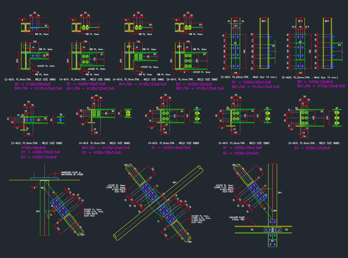
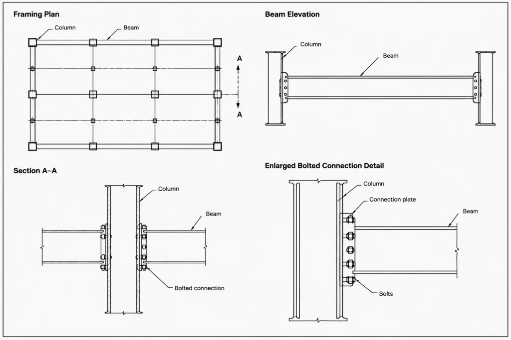
A general framing plan must show a large area, while a connection detail must show closely spaced components. Trying to use one drawing scale for every view usually produces either an oversized sheet or an unreadable detail.
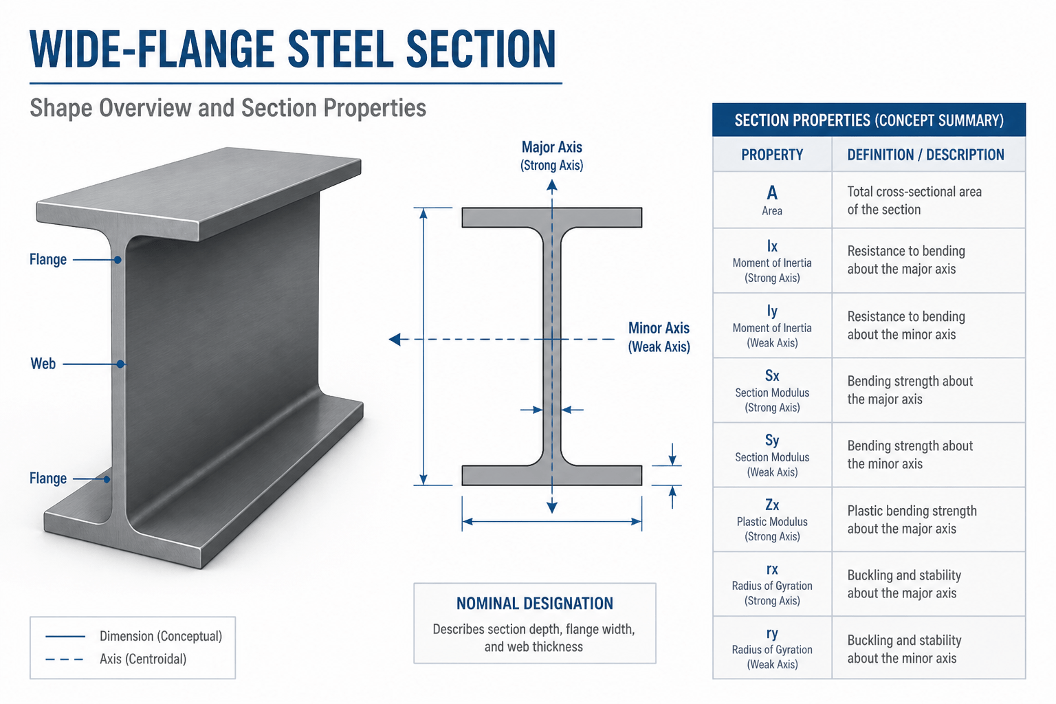
The better approach is to select a presentation scale according to the information density of each view. A framing plan may emphasize grids, member marks, orientation, and major dimensions. An enlarged connection view may emphasize plate edges, bolt lines, weld locations, and fit-up relationships. A section through a W-shape or HSS member may require enough enlargement to distinguish flanges, webs, walls, hidden elements, and nearby components.
Scale selection should therefore follow communication needs, not merely available blank space. If a detail becomes legible only after text is reduced excessively or leaders are crowded together, it may need a larger view, a separate section, or a simplified representation.
Annotation Must Remain Readable
Text, dimension strings, weld symbols, bolt callouts, section marks, and detail bubbles are sheet communication elements. They should have a consistent plotted appearance even when the underlying views use different scales.
Problems arise when annotation is treated as ordinary model geometry and scaled along with the steel. Text may become tiny in one view and oversized in another. Arrowheads may obscure holes, center marks may dominate a plate, and line spacing may collapse when a dense detail is reduced.
A practical sheet review should consider:
- Whether text remains legible at the intended output size.
- Whether dimension lines can be distinguished from object and extension lines.
- Whether leaders point unambiguously to the intended component.
- Whether section and detail references can be found without searching.
- Whether hidden lines and centerlines remain meaningful rather than merging into visual clutter.
- Whether duplicate annotations appear when model information is shown in more than one view.
Unit Problems Can Look Like Scale Problems
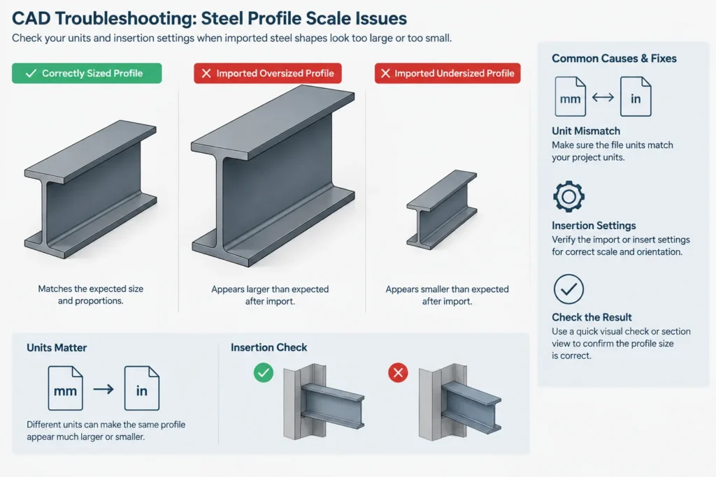
Imported steel profiles, connection details, and consultant backgrounds may use different drawing units or insertion assumptions. An imported object that appears far too large or too small is not necessarily a viewport issue. The object itself may have been converted incorrectly.
Before manually scaling imported geometry, check what the source file represents. Determine whether it uses imperial or metric units, whether it was drawn at actual size, and whether its insertion process applied a conversion. Also check whether a block or grouped object contains geometry created under a different unit convention.
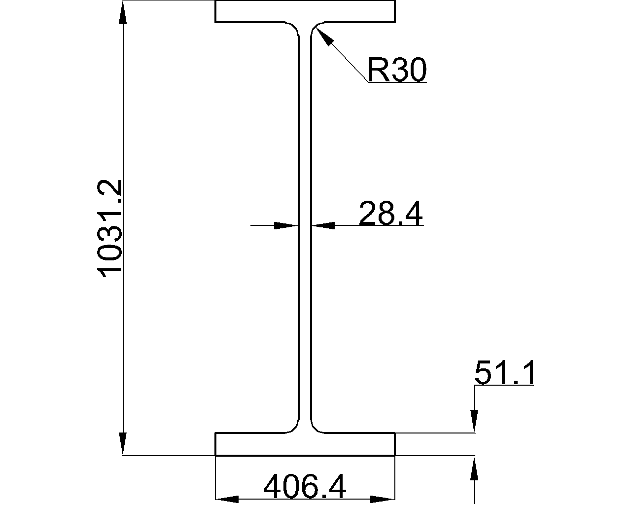
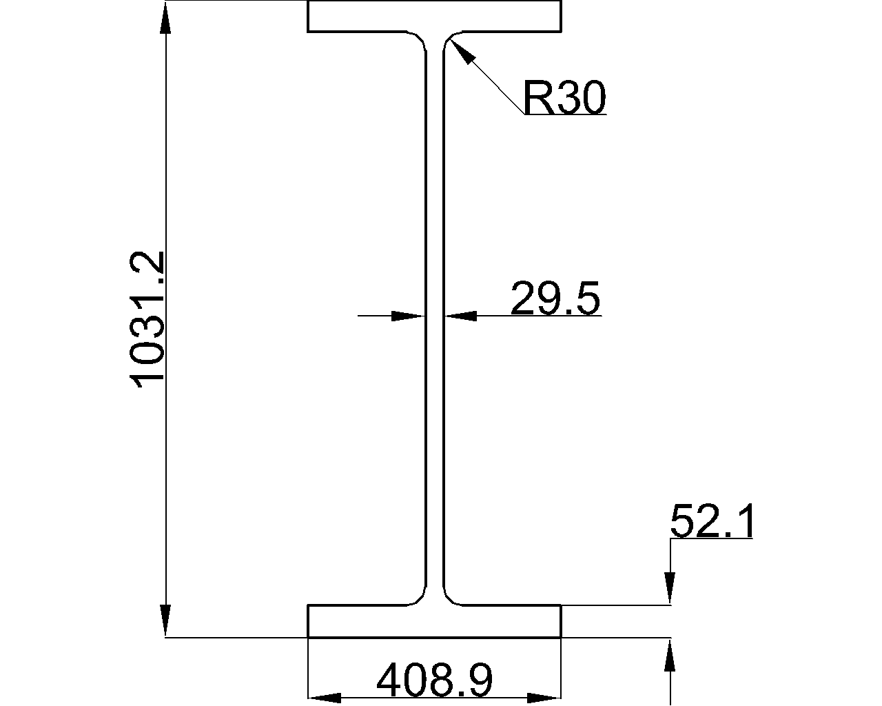
Manual scaling can make an object look correct while leaving its dimensional meaning uncertain. For a steel shape, visual resemblance is not enough. The designation and verified dimensions must agree with the geometry before the profile is used for detailing or clearance studies.
Why PDF Measurements Require Caution
PDF measuring tools are convenient, but their results depend on the source output, page size, calibration, and subsequent document processing. A correctly plotted sheet may later be cropped, combined, rasterized, or resized. Each operation can affect measurement reliability without visibly changing the dimensions printed on the drawing.
If a PDF measurement is needed for a general check, first calibrate it against a clearly identified dimension in the same view. Do not assume that calibration from one detail applies to another detail on the page; sheets can contain views at several scales. Also avoid calibrating from a line whose endpoints are ambiguous, such as a thick object line, break line, or symbolic member representation.
When a required dimension is missing or contradictory, the correct response is to resolve the information through the project coordination process rather than infer precision from the PDF.
Scale and Structural Steel CAD Blocks
Steel shape CAD blocks can speed drafting, but they need to enter the drawing with correct units, orientation, and actual dimensions. A block should not be enlarged or reduced merely to resemble a specified member.
After insertion, compare a dependable geometric feature with verified shape data. Confirm the section designation, depth direction, flange or leg orientation, insertion point, and any rotation. For HSS, angles, channels, tees, and other asymmetric or open shapes, orientation is especially important because an outline can appear plausible while facing the wrong direction.
Keep symbolic representations separate from dimensionally accurate section profiles. A simplified framing-plan symbol may communicate member location effectively, but it should not be mistaken for an exact cross section suitable for connection fit checks.
A Practical Drawing-Scale Review Workflow
- Confirm drawing units. Establish the unit convention of the main file and each imported reference.
- Verify actual-size geometry. Check known member lengths, grid spacing, plate dimensions, or shape dimensions without relying on sheet appearance.
- Review view scales. Make sure each plan, elevation, section, and detail has an intentional presentation scale.
- Check view identification. Clearly identify details whose scale differs from surrounding views, and identify views that are intentionally not to scale.
- Inspect annotation. Review plotted text height, leader clarity, line spacing, symbols, and overlapping dimensions.
- Test the final output. Review the issued PDF or print format rather than checking only the CAD workspace.
- Compare a known distance. Use a labeled dimension to detect unintended output resizing, while keeping the written dimension as the controlling information.
- Resolve discrepancies. If geometry, labels, and dimensions disagree, correct or formally clarify the source rather than hiding the conflict with view scaling.
Common Warning Signs
- A steel profile has the correct name but does not match verified section dimensions.
- Dimension values change after objects are manually enlarged or reduced.
- Text size varies dramatically between details on the same sheet.
- A PDF measurement disagrees with several written dimensions.
- Imported backgrounds appear consistently too large or too small.
- Hole symbols look correct visually, but their coordinate geometry does not match the callouts.
- A detail has no scale identification even though users are likely to measure it.
- Different views of the same connection show conflicting proportions or component locations.
Use Scale to Communicate, Not to Define
Structural steel drawing scale is primarily a presentation tool. Actual geometry belongs in the model or drawing database, while dimensions and notes communicate the controlling requirements. View scales make that information readable across framing plans, elevations, sections, and connection details.
A reliable workflow keeps those roles separate. Draw steel geometry at its intended size, verify imported content and units, select view scales for clarity, and check the final output. Most importantly, do not convert an apparent distance on a sheet into fabrication information when the controlling dimension has not been established.