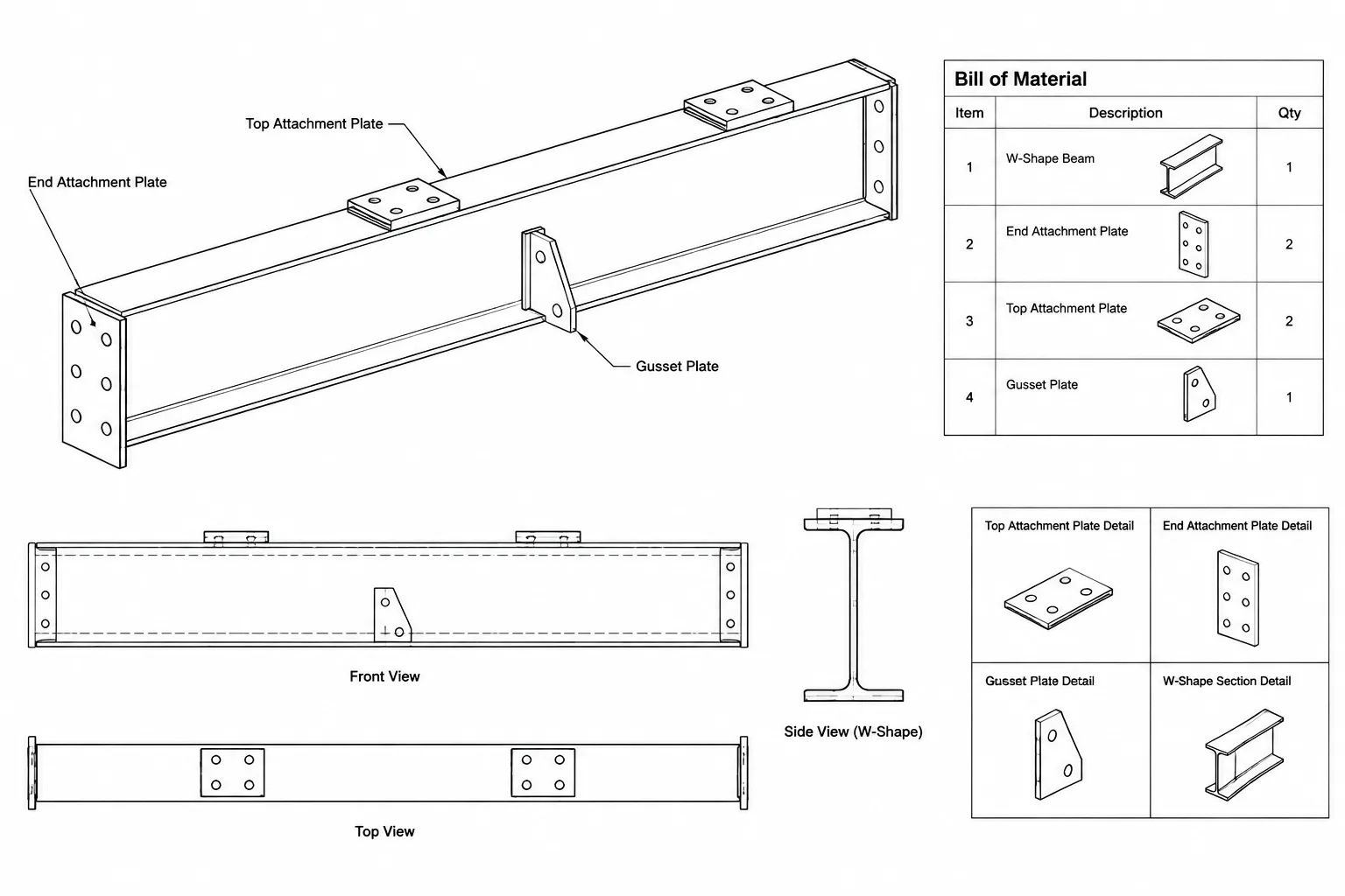
A structural steel bill of material organizes the components represented on a shop drawing into a list that can support purchasing, cutting, fabrication, tracking, and drawing review. It may also be called a material list, material takeoff, or BOM. The exact format varies among fabricators, projects, and detailing systems, but the underlying purpose is consistent: every physical item in an assembly must be identified clearly enough to connect the drawing geometry with the material required to fabricate it.
A useful bill of material is more than a summary of steel weight. It links main members, plates, angles, tees, HSS components, stiffeners, connection material, and other parts to their marks and quantities. Errors in this list can remain hidden even when the assembly views look correct, so BOM review is an important part of the detailing workflow.
Main material and detail material
On an assembly drawing, the main material is generally the principal member around which the shipping piece is built. For a beam assembly, it may be a W-shape. For a column, it may be a W-shape, HSS, pipe, or built-up member. A brace assembly could use an HSS, angle, channel, tee, or another specified section.
Detail material includes the separate components attached to or supplied with that main member. Typical examples include end plates, shear plates, stiffeners, clip angles, cap plates, base plates, connection tees, and small attachment plates. Terminology is not universal: some organizations use terms such as submaterial, secondary material, loose material, or attached material. The project drafting standard should control the naming convention.
The distinction is primarily organizational. Calling a part detail material does not imply that it is structurally unimportant. A relatively small plate may be essential to the connection load path, erection stability, or fit-up of the assembly.
Typical information in a steel material list
The columns included in a structural steel bill of material depend on the company workflow and drawing type. Common fields include the following:
| Field | What it identifies | Common checking concern |
|---|---|---|
| Piece or part mark | The identifier assigned to a member or individual component | Confirm that the mark agrees with labels in the drawing views |
| Quantity | The number of identical items required under the stated counting basis | Determine whether the quantity is per assembly, per mark, or for the entire drawing |
| Material description | The rolled shape, HSS, angle, channel, tee, plate, bar, or other product form | Check the complete designation rather than relying on nominal depth alone |
| Thickness or size | Relevant dimensions for plates and other material | Verify that the listed size matches the controlling drawing callout |
| Length | The required piece length or listed stock-related length | Do not assume that it is the same as work-point or overall assembly length |
| Material grade | The specified material classification when shown in the BOM | Coordinate with project specifications and general notes |
| Weight or mass | A calculated value for an item or group of items | Confirm the unit, source property, quantity basis, and rounding method |
| Remarks | Special tracking, fabrication, or supply information | Make sure remarks do not conflict with details or notes |
Not every list contains all of these fields. Information omitted from the BOM may instead be controlled by notes, specifications, model data, or other schedules. Reviewers should understand the document hierarchy rather than expecting the material list to carry every requirement.
Assembly marks are not the same as part marks
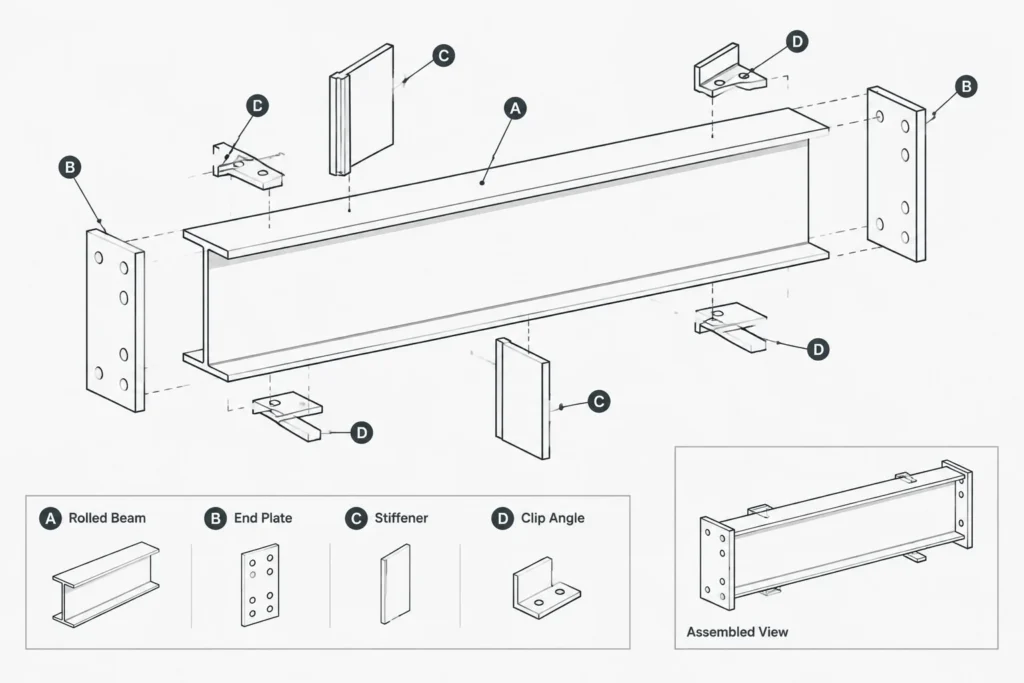
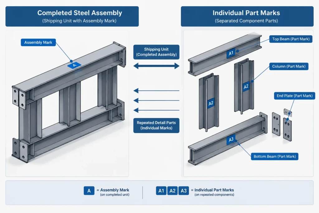
An assembly mark identifies a completed fabricated or shipping unit. A part mark identifies one component used to create that unit. For example, a beam assembly may have its own mark while its plates and angles carry separate part marks. Several assemblies can use an identical detail part, and one assembly can contain multiple pieces carrying the same part mark.
This distinction affects quantity calculations. If an assembly requires two identical stiffeners and several assemblies share the same mark, the project requirement is not represented by the per-assembly quantity alone. Conversely, a drawing list may already show a total quantity, so multiplying it again would overstate the material.
Every BOM should therefore have a clear counting basis. The title block, list heading, shop standard, or detailing software output may establish whether quantities apply to one assembly, all assemblies on the sheet, or the full project database.
Length means different things in different contexts
Steel detailing uses several kinds of length, and the number in a material list must be interpreted in context. A member may have a work-point length, detailed length, cut length, ordered length, or overall assembly length. End plates, bearing components, skewed cuts, copes, setbacks, and projecting attachments can cause these values to differ.
For straight rolled material with square ends, the listed piece length may appear simple. For a sloped brace, mitered HSS, skewed beam, or bent component, a single length field may not communicate all cutting geometry. The fabrication details and model geometry remain necessary.
Plate descriptions require similar care. A rectangular plate can often be summarized by thickness, width, and length, but an irregular plate also needs its detailed profile. The BOM dimensions should not be treated as a substitute for hole coordinates, clipped corners, notches, tapers, or curved edges shown elsewhere.
Shape descriptions must remain complete
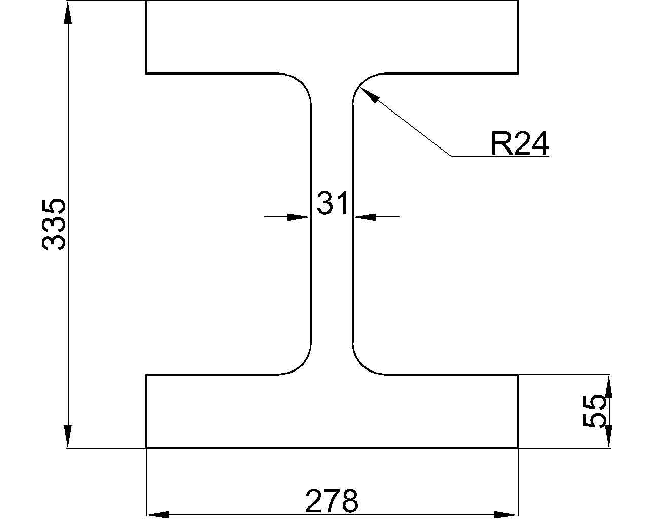
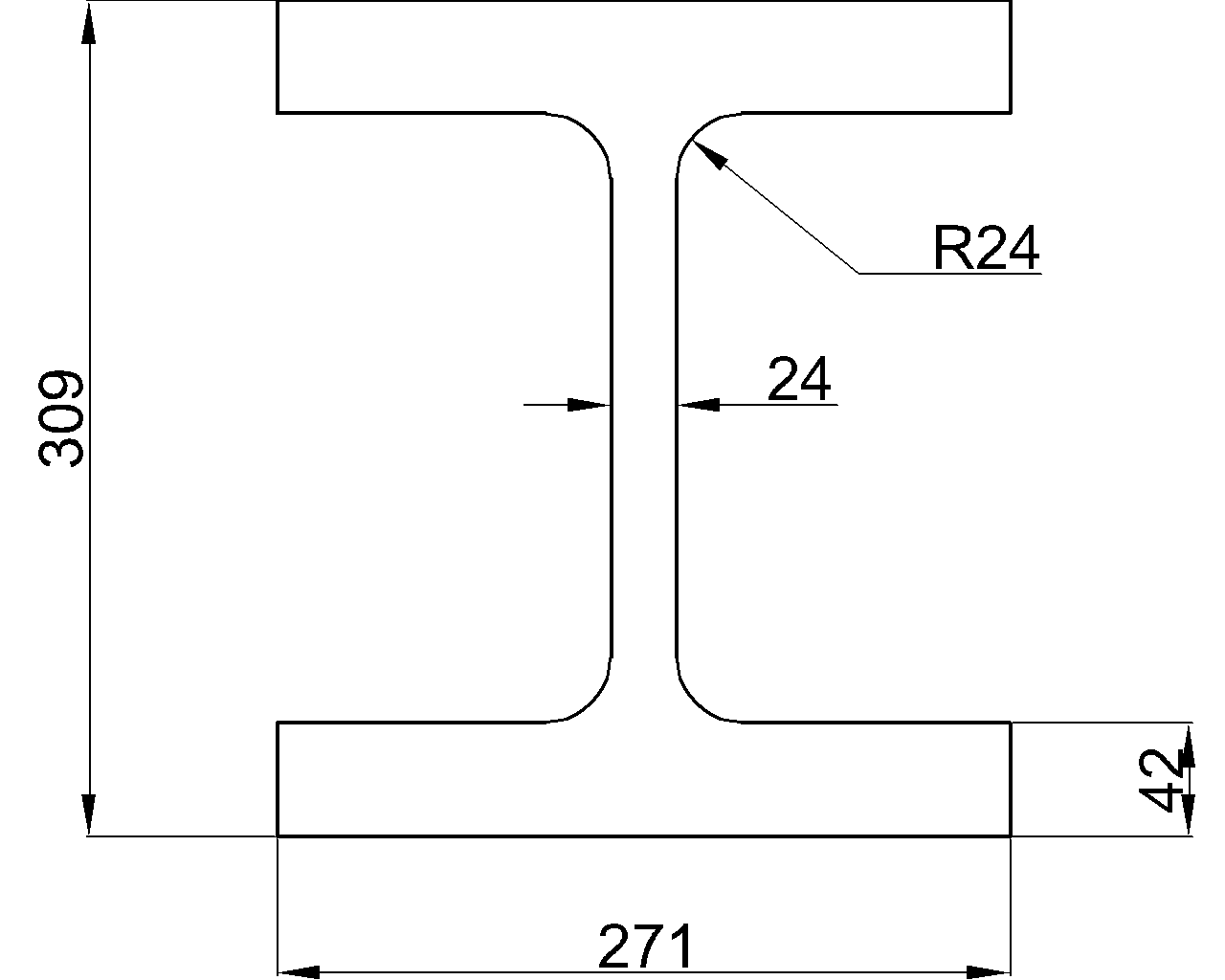
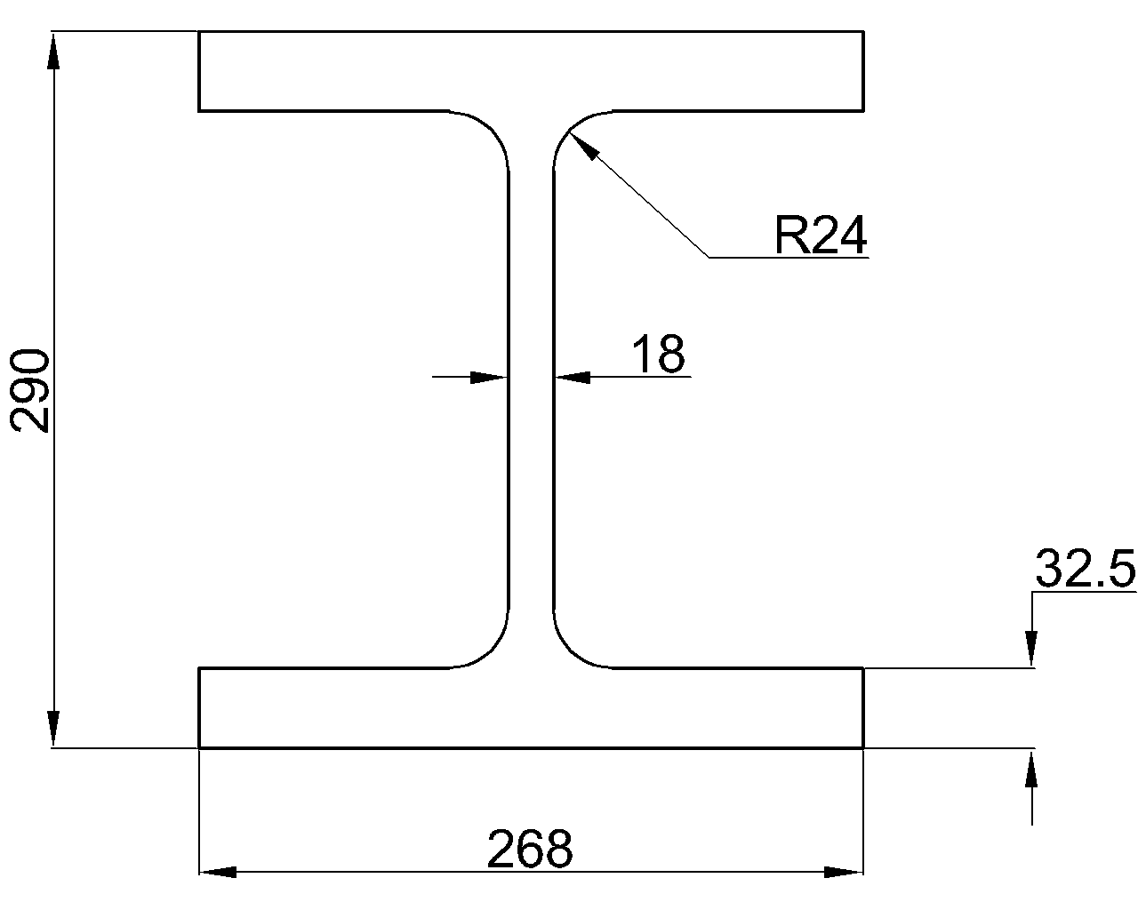
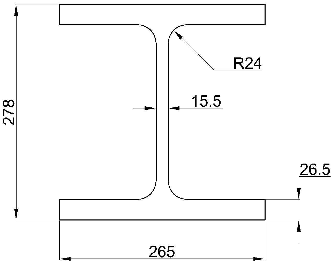
Rolled shapes should be listed with their full designation. Members in the same nominal depth family can have different flange widths, web and flange thicknesses, weights, and section properties. Abbreviating a W-shape to depth alone does not uniquely define it.
HSS descriptions also need the complete specified size and wall information. Angles require both leg sizes and thickness, while unequal-leg angles may additionally require orientation information in the drawing views. Channels and tees must be identified by their complete shape designations. Plate descriptions should follow the project’s established dimension order so that width and length are not accidentally reversed.
The BOM identifies the product or part; the views identify its orientation and placement. Both sources must agree.
Weight and mass are calculated outputs, not geometry controls
A weight column can help with handling, shipping, estimating, and general error detection, but it should not control the geometry of a part. Rolled-shape weight is commonly based on published unit weight and listed length. Plate and irregular-part calculations may depend on area, thickness, density assumptions, cutouts, and the conventions of the software or fabricator.
Small differences can result from rounding, treatment of holes, exact versus simplified geometry, or whether attached items are included. A reviewer should investigate a meaningful discrepancy rather than forcing the drawing to match a rounded weight value. The shape designation, dimensions, material requirements, and approved geometry remain the primary controls.
A practical BOM checking workflow
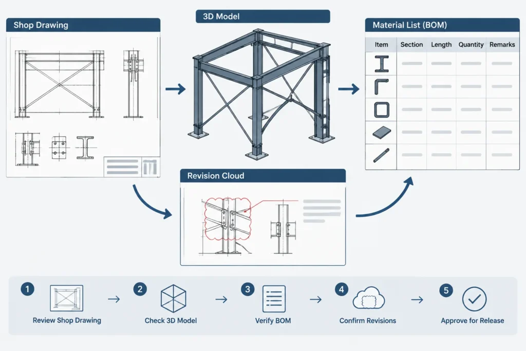
1. Match every drawing label to a list entry
Trace the main member and each marked attachment in the plans, elevations, sections, and details. A part shown in a view but absent from the material list is a warning sign. A listed part that cannot be found in any view also requires investigation.
2. Reconcile quantities
Count repeated stiffeners, clip angles, end plates, and other mirrored or paired items. Check whether near-side and far-side components are truly identical. Handed parts may look similar while requiring separate marks because holes, bevels, or attachment locations are mirrored.
3. Compare descriptions with callouts
Verify shape designations, plate thicknesses, widths, lengths, and grades against the controlling notes and dimensions. Avoid checking only the visible text: a CAD block or model object can retain an outdated property after a graphical edit.
4. Review cut geometry separately
Confirm that copes, miters, slots, notches, bevels, and irregular plate profiles are fully detailed. A correct rectangular bounding size does not prove that the finished part geometry is correct.
5. Check revision effects
When a connection changes, review the entire chain of affected information: part geometry, part mark, quantity, material description, assembly weight, notes, and revision indicators. Replacing a plate in a detail without updating the BOM can release conflicting fabrication information.
6. Compare the BOM with the model and source documents
Automated extraction reduces manual entry but does not eliminate checking. Model object classification, duplicate parts, suppressed items, incorrect material attributes, or stale reports can produce a clean-looking but inaccurate list. Compare the output with the latest structural documents and approved connection information.
Using the bill of material as a coordination tool
A well-structured BOM provides a compact audit of an assembly. It can reveal a missing attachment, an inconsistent shape designation, an unexpected quantity, or an obsolete component after a revision. It also helps connect engineering intent, detailing geometry, shop operations, and material tracking.
However, the material list should always be read together with drawing views, dimensions, notes, specifications, and current project revisions. It describes what material belongs to the assembly; it does not independently establish connection adequacy, fabrication acceptance, or suitability for a specific project. Those determinations require review under the applicable project requirements.