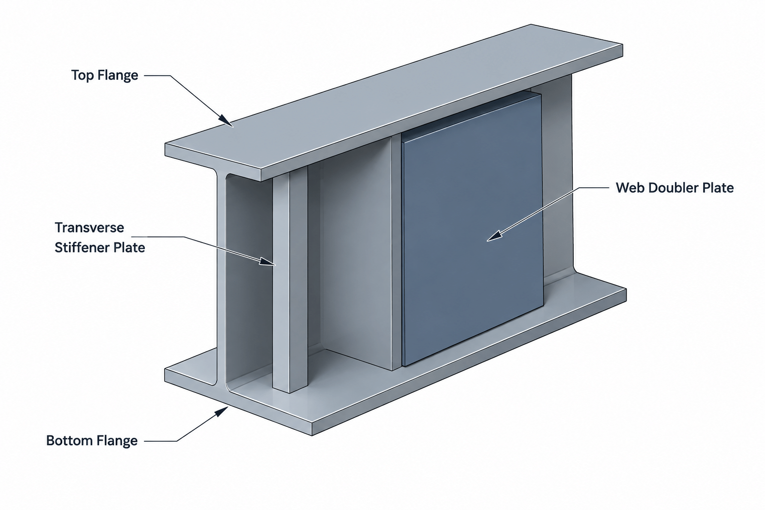
Stiffener plates and doubler plates both reinforce structural steel members, but they do not perform the same role. A stiffener commonly transfers or distributes force through a member at a concentrated load or connection. A doubler plate typically reinforces a localized region of an existing web or another plate element by adding material alongside it.
The distinction matters in design communication, shop detailing, material lists, and CAD modeling. Calling every reinforcement plate a “stiffener” can obscure its intended force path. Calling a plate a “doubler” without identifying the element being reinforced can create uncertainty about its location and limits. The contract drawings, connection design, project specifications, and responsible engineer’s instructions must govern the final configuration.
What is a stiffener plate?
A stiffener plate is a plate attached to a structural member to strengthen or stabilize a particular part of its cross section. On a W-shape, stiffeners are often arranged transverse to the web and located between the flanges. Depending on the connection and loading, they may help transfer a concentrated force between a flange and the web, distribute force into the member, or restrain a slender plate element.
Common descriptions include:
- Web stiffener: A plate attached to the web, often extending toward one or both flanges.
- Transverse stiffener: A plate oriented across the member depth rather than along its length.
- Bearing stiffener: A stiffener associated with a concentrated reaction or bearing force.
- Continuity plate: A plate used in certain moment-connection regions to continue flange force through a supporting member.
- Longitudinal stiffener: A plate or element running generally parallel to the member axis to reinforce a web or plate panel.
These terms describe function or orientation, but office and fabricator terminology may vary. A detail should show the plate clearly rather than relying on the name alone.
What is a doubler plate?
A doubler plate adds thickness to a localized portion of another element. In structural framing, a web doubler is commonly placed against the web of a W-shape in a connection region. It creates a reinforced web zone without replacing the original member web.
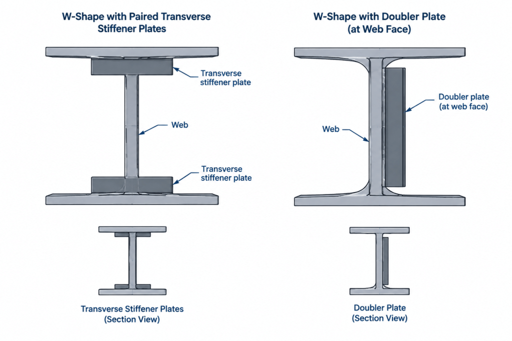
Doubler plates may be located on one side or both sides of a web. Their boundaries may terminate within the member depth, extend near the flanges, or continue beyond the immediate connection zone. Those choices affect force transfer, welding access, fit-up, and inspection, so they must not be inferred from a generic detail.
The word “doubler” does not necessarily mean that the combined thickness is exactly twice the original thickness. It describes the reinforcing arrangement, not a fixed thickness relationship.
Stiffener plates vs. doubler plates at a glance
| Detailing question | Stiffener plate | Doubler plate |
|---|---|---|
| Typical orientation | Often transverse to the member web or placed between flanges | Usually parallel to and in contact with the element being reinforced |
| Primary concept | Transfers, distributes, or stabilizes forces through the section | Adds local thickness or reinforcement to an existing plate element |
| Typical W-shape location | At one or both sides of the web, extending across part or all of the clear web region | Against one or both faces of the web within a defined connection zone |
| CAD appearance in elevation | Often appears as a narrow vertical plate at a specific station | Often appears as a larger rectangular or shaped plate covering a web region |
| Key fit-up concern | Flange fillets, cope shape, end preparation, and access | Contact with the web, boundary weld access, interference, and trapped spaces |
This comparison is conceptual. Actual plate geometry and weld requirements depend on the engineered detail.
Where these plates appear in steel framing
Beam reactions and concentrated loads
Stiffeners may be shown near a support or beneath a concentrated load where force enters a beam over a relatively short length. The plate arrangement can help carry force between the flange and web. A drafter should coordinate the stiffener station with the actual load or reaction location rather than placing it from a visually convenient reference.
Moment-connection regions
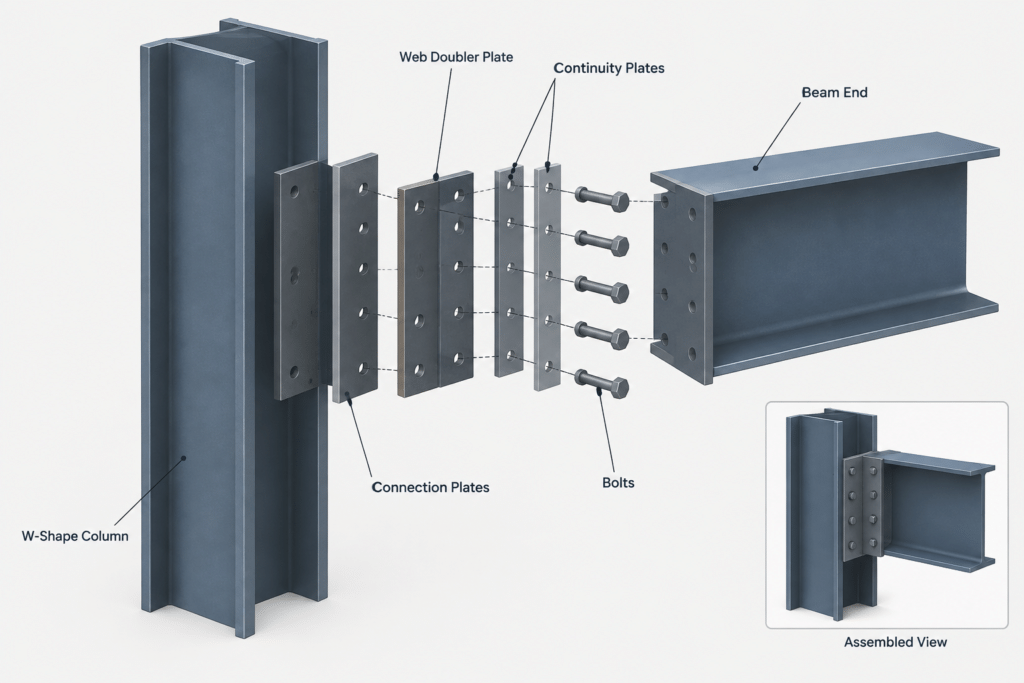
Column webs in moment-connection zones may include continuity plates, doubler plates, or both. The continuity plate and web doubler address different parts of the connection force path. In drawings, their edges can overlap in projection, making sections and hidden-line conventions especially important.
Equipment supports and transfer points
Members supporting equipment, hangers, brackets, or transfer elements may have localized reinforcement. The plate name alone does not identify whether it is intended for bearing, force transfer, web stability, or another design function. Detail references and connection notes should make the relationship clear.
Built-up members and plate girders
Built-up members may use transverse or longitudinal stiffeners as part of the web system. These should not automatically be detailed like stiffeners fitted into a rolled W-shape. The flange-to-web geometry, weld arrangement, and fabrication sequence can be substantially different.
Geometry that must be defined on drawings
A useful reinforcement-plate detail establishes enough geometry for fabrication without requiring the shop to guess design intent. Relevant information may include:
- Plate thickness, width, length, and material designation.
- Quantity and whether the quantity is per member, per side, or per location.
- The member face or side on which the plate is installed.
- Longitudinal location from a stable work point, grid, member end, or connection centerline.
- Vertical limits relative to flange faces, member centerlines, or other defined references.
- Required fit, gap, clip, cope, or corner treatment.
- Weld location and extent, including which edges are intentionally not welded.
- Whether similar-looking plates at opposite sides are identical, mirrored, or different.
A note such as “provide stiffener” is not a complete fabrication detail. Conversely, a detailed plate outline can still be ambiguous if its reference point and member face are not identified.
Rolled fillets and plate fit-up
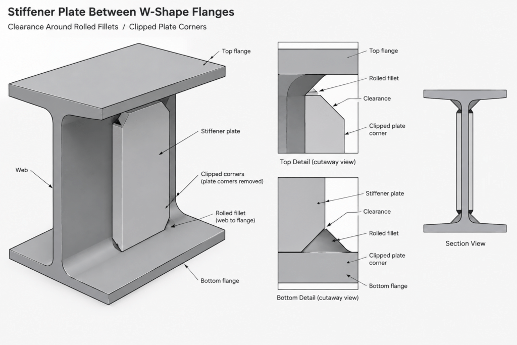
The inside corners of a rolled W-shape are not sharp. A stiffener placed between the flanges must account for the rolled web-to-flange fillets. Drawing the stiffener as a plain rectangle extending into those curved regions can produce an impossible CAD fit and an incomplete shop detail.
Depending on the engineered and fabrication requirements, the plate may use clipped corners, shaped transitions, or another specified treatment near the fillets. The detail should distinguish between nominal linework and actual fabrication geometry. Shape-table dimensions and verified member geometry should be used when establishing available space.
Doubler plates present a different fit problem. Because a doubler lies alongside the web, the detail must account for nearby flanges, fillets, existing welds, connection plates, bolts, and access for welding. A plate that fits in a clean elevation may still be obstructed in a section or three-dimensional model.
Weld callouts and force-path clarity
The plate outline and weld symbol should be read together. Similar plates can behave differently depending on which edges are connected and where force enters the assembly. Avoid extending a weld graphically around a plate simply because a CAD polyline makes that easy.
For each plate, verify:
- Which plate edges receive welds.
- Which side of the joint the symbol applies to.
- Whether the weld is continuous, intermittent, limited in length, or terminated at a defined point.
- Whether flange welds and web welds use different instructions.
- Whether the work is performed in the shop or field.
- Whether nearby welds create access or sequencing conflicts.
Weld type, size, length, termination, and inspection requirements are design and project-specific. They should be taken from approved design information rather than copied from a typical detail without review.
CAD and model coordination workflow
A disciplined workflow helps prevent reinforcement plates from becoming disconnected pieces of drafting geometry.
- Confirm the supporting member. Use the correct shape and actual orientation. Do not assume that every column web faces the same direction.
- Establish the connection work point. Locate the beam centerline, flange force line, reaction point, or other governing reference.
- Model the plate by function. Place a stiffener transverse to the web when required; place a doubler against the correct web face rather than at the member center plane.
- Check rolled-shape geometry. Review flange slopes where applicable, web-to-flange fillets, clear web space, and actual flange thickness.
- Add surrounding connection parts. Include bolts, plates, weld-access regions, copes, and framing members before accepting the fit.
- Generate multiple views. An elevation alone may hide a wrong-side plate or a collision with an adjacent component.
- Coordinate the bill of material. Match plate marks, quantities, materials, and dimensions to the drawing views.
CAD blocks and typical connection details are useful starting references, but they should not control plate dimensions or weld information. The project-specific design must remain the source of truth.
Common detailing errors
- Using the terms interchangeably: This can conceal whether a plate crosses the web space or lies against the web face.
- Centering a doubler on the member plane: A real doubler normally occupies a specific face and has physical thickness.
- Ignoring the rolled fillet: A sharp-cornered stiffener may overlap the actual shape.
- Leaving the plate station undefined: Small longitudinal shifts can separate the reinforcement from the force it was intended to receive.
- Assuming symmetry: Framing, access, or connection forces may require different plates on opposite sides.
- Copying welds from another detail: Similar plate outlines do not establish identical weld requirements.
- Omitting section views: Elevations may not reveal plate side, thickness, clearances, or layered components.
A practical review checklist
Before issuing a reinforced connection detail, check that the plate type, function, location, geometry, and attachment are consistent across the plan, elevation, section, model, and material list. Confirm that the plate clears rolled fillets and adjacent connection components. Review whether each plate is shop- or field-installed and whether the proposed sequence permits access.
Most importantly, separate drafting interpretation from engineering decisions. A detailer may resolve graphical representation and documented fit, but should not choose plate dimensions, alter welds, or substitute a stiffener for a doubler without authorized design direction. Clear terminology supports coordination; complete geometry makes the terminology buildable.