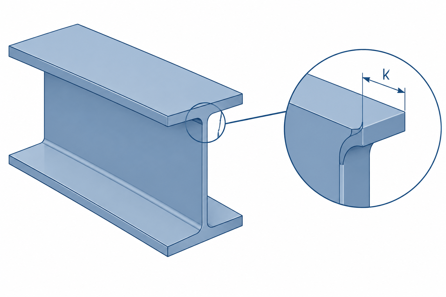
A wide-flange section may look like three flat plates in a simplified drawing, but a rolled shape does not have sharp inside corners where its web meets its flanges. These transitions contain rolled fillets. The steel shape k dimension helps designers and detailers locate that transition region and avoid placing plates, welds, bolts, or cuts where the idealized flat surfaces no longer exist.
This small table entry has practical consequences. Ignoring it can produce stiffeners that do not fit, weld details with poor access, connection plates that interfere with a flange fillet, and CAD models that imply impossible sharp-corner geometry.
What does the steel shape k dimension represent?
For a typical W shape, the k dimension describes the distance from the outside face of a flange toward the web, ending at a defined location associated with the toe of the rolled web-to-flange fillet. It therefore identifies the approximate boundary between the flange-web transition and the flatter portion of the web.
The dimension is usually taken perpendicular to the flange face. It is not the same as flange thickness, even though flange thickness contributes to the distance. The remaining portion represents the fillet and transition region.
Shape databases may distinguish between a design-oriented value and a detailing-oriented value. Common labels include kdes and kdet, although table headings and definitions should always be checked in the specific reference being used.
- Design value: Used when the analytical definition of the flange-web transition matters.
- Detailing value: Intended to help establish practical clearance from the rolled fillet and expected production variation.
A detailing value is not a universal answer for every connection. Fabrication tolerances, weld size, plate thickness, coating, erection clearance, access, and the connection configuration can require additional space.
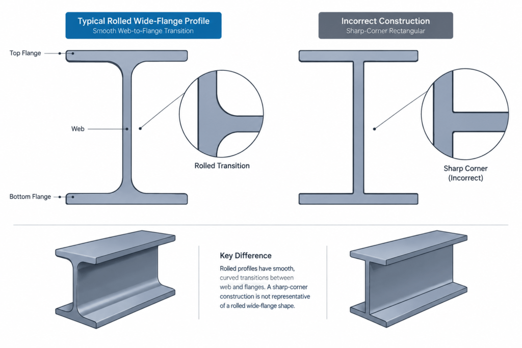
Why the flange-web corner is not square
W shapes, channels, and many other open sections are produced by rolling heated steel through shaped rolls. Material flows through the flange-web junction rather than forming an abrupt machined corner. The resulting fillet improves the continuity of the rolled section, but it also occupies space that may appear open in a stick diagram or sharp-corner CAD block.
A plate pushed tightly into this region will contact the curved transition before it contacts both nominally flat surfaces. A fabricator may then need to clip, cope, grind, or otherwise modify the plate. Unplanned field or shop modifications can affect fit-up, weld access, cost, and the intended load path.
kdes, kdet, and fillet radius are not interchangeable
One of the most common drafting mistakes is treating a listed k value as if it were a fillet radius. The two describe different things. A k dimension locates a transition relative to the flange face; a radius describes the curvature of an arc.
A single k value generally does not provide enough information to reconstruct the exact rolled contour. The actual transition may also vary within permitted manufacturing tolerances. Consequently, an arc inferred from flange thickness and k should not be presented as verified mill geometry unless the governing data explicitly defines that construction.
| Item | What it communicates | Typical use |
|---|---|---|
| Flange thickness | Nominal thickness of the flange at the defined measurement location | Section reference, connection layout, and calculations |
| k dimension | Distance from the flange face to a defined fillet-to-web transition location | Locating the web region affected by the rolled fillet |
| Detailing k value | A clearance-oriented boundary provided by the applicable shape reference | Clipping plates and avoiding interference |
| Fillet radius | Geometric curvature when a radius is specifically defined | Accurate profile modeling or fabrication geometry |
Connection details affected by rolled fillets
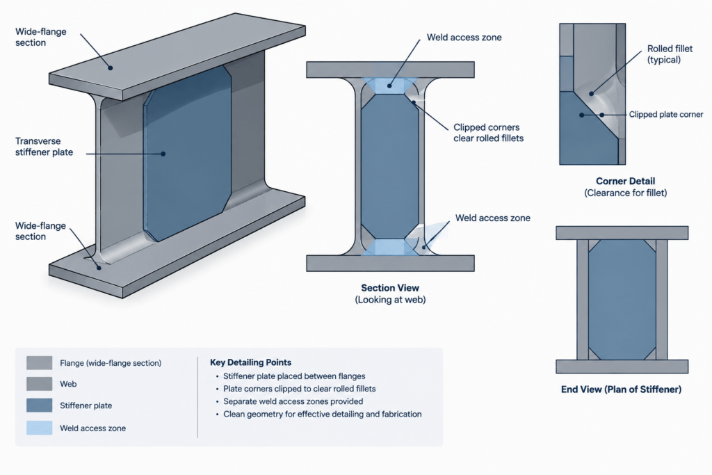
Transverse stiffeners
A stiffener extending between W-shape flanges cannot normally be modeled as a perfect rectangle with square corners. Its corners may require clips or shaped cuts so that the plate clears the rolled fillets. The selected cut must also leave suitable access for the specified welds.
Clearance should be intentional and shown consistently. An arbitrary CAD chamfer can be just as misleading as no chamfer because it may not reflect the governing shape, fabrication method, or weld detail.
Connection plates near a flange
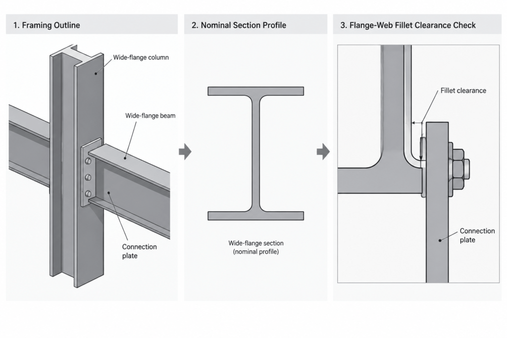
Shear connection plates, continuity plates, diaphragms, bearing components, and other attachments may approach the flange-web junction. Their edges and weld terminations should be checked against the fillet zone. A plate edge aligned only from nominal flange thickness can extend into the curved transition.
Bolts and holes
The fillet region can influence available flat-web space near a flange. Hole locations must satisfy the project’s connection design and fabrication requirements while also remaining on usable material. The k dimension is a geometric warning boundary, not a substitute for checking hole spacing, edge distance, installation access, or connection strength.
Beam copes and notches
End copes are often coordinated with flange geometry, connection plates, welds, and supporting-member fillets. A cope that works in a simplified line model may conflict with the actual rolled profile. Cope geometry can also affect structural behavior, so it should come from the engineered detail rather than being improvised from the k value alone.
How to use k dimensions in a CAD workflow
A practical drafting workflow separates nominal section representation from connection-level clearance checks.
- Confirm the exact designation. Do not transfer a k value from a visually similar W shape or another member in the same nominal depth group.
- Identify the table definition. Determine whether the available field is design-oriented, detailing-oriented, or a differently defined dimension.
- Use a reliable profile source. Avoid scaling a PDF, tracing a catalog image, or estimating the fillet from screen graphics.
- Model the required level of detail. A framing plan may only need a simplified outline, while a stiffener or connection detail requires explicit fillet clearance.
- Keep clearance editable. Use parameters, construction lines, or named reference geometry rather than burying an unexplained clip inside a block.
- Check both flanges. Do not assume a copied detail is correctly oriented after mirroring or rotating the member.
- Coordinate with weld geometry. Plate clearance and weld access are related but separate checks.
- Flag uncertain geometry. If the source does not define the rolled contour, label the model as nominal instead of implying fabrication accuracy.
How the concept changes for other steel shapes
The familiar W-shape interpretation should not be applied indiscriminately to every section family.
- Channels: Channels have an unsymmetrical open profile and rolled transitions at the web-flange junctions. Orientation matters when arranging plates and bolts.
- Structural tees: A rolled tee produced from a parent shape retains a stem-to-flange transition. Use data for the designated tee rather than assuming the parent section’s drafting dimensions can be copied without review.
- Angles: Angles have an inside root transition and rounded outer toes. Angle detailing may depend on both leg geometry and the available flat area.
- HP shapes: HP sections resemble wide-flange shapes but form a separate shape family. Their own published properties and detailing dimensions should be used.
- HSS: Rectangular and square HSS have rounded corners created by their manufacturing process. W-shape k terminology does not define those corner regions.
Common mistakes to avoid
- Drawing the web and flanges as intersecting rectangles in a fabrication-level detail.
- Assuming k is a radius and creating an arc directly from it.
- Using a design-oriented table value as guaranteed physical clearance.
- Copying a stiffener clip from one member size to another without checking the new section.
- Letting a plate clear the fillet while overlooking weld access or erection tolerances.
- Dimensioning bolts from a simplified outline without verifying usable flat-web space.
- Treating a visually accurate 3D model as proof of actual mill contour or fabrication fit.
A small dimension with a large detailing role
The steel shape k dimension connects section-table data with real connection geometry. It helps identify where the nominally flat web gives way to the rolled flange-web transition, allowing plates, holes, cuts, and welds to be arranged more realistically.
Use the value according to its stated definition, keep it separate from an assumed fillet radius, and verify connection-specific clearance rather than relying on appearance alone. That approach produces cleaner CAD files, more useful shop details, and fewer avoidable fit-up conflicts.


