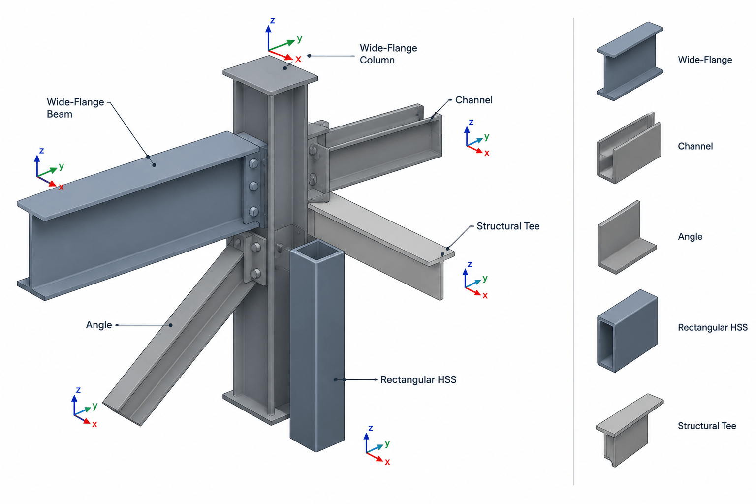
A steel shape designation identifies a cross section, but it does not fully describe how the member is positioned in a structure. A channel can face either direction, an angle can be toe-up or toe-down, and a rectangular HSS can be placed on its narrow or wide face. Even a wide-flange member may be sloped, skewed, rolled, or reversed end for end.
Clear steel member orientation is therefore essential when moving between design drawings, shop details, erection plans, and CAD or BIM models. The goal is not merely to make the section look correct in one view. The member must have a consistent three-dimensional position, meaningful local axes, and connection geometry that agrees at both ends.
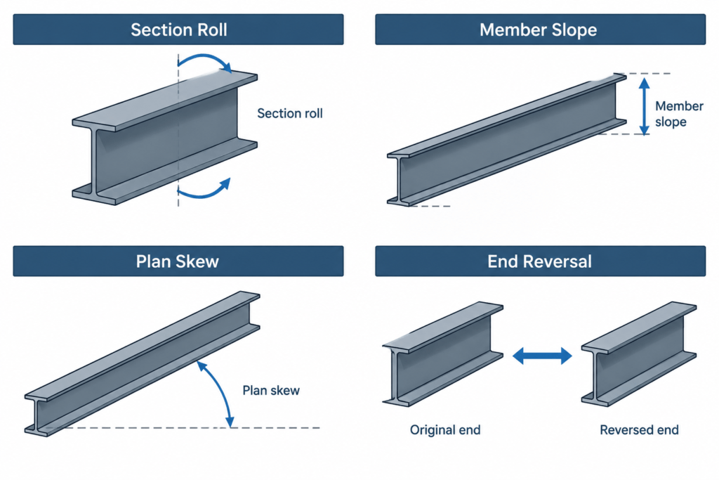
The four parts of member orientation
Several different geometric changes are often described casually as “rotation.” Separating them into distinct concepts helps prevent modeling and detailing errors.
| Orientation concept | What changes | Common drawing or model effect |
|---|---|---|
| Section rotation or roll | The cross section rotates about the member’s longitudinal axis | Flanges, legs, webs, or HSS faces change direction |
| Slope | The member rises or falls along its length | End elevations differ |
| Skew | The member runs at an angle in plan relative to the primary grid or framing | Connections may require angled plates, cuts, or bolt layouts |
| End reversal | The start and end of the member are exchanged | Local-axis directions and end-specific details may change |
A member can have all four conditions at once. For example, a sloping channel may also be skewed in plan, rolled so its toes face outward, and assigned a particular start end for connection data.
Local axes versus global axes
Structural models and CAD workflows commonly use both global and local coordinate systems. Global axes describe the building or project space. Local axes belong to an individual member and move with it.
The member’s longitudinal local axis typically follows its work line from the assigned start point to the end point. The other two local axes establish the cross-section orientation. Their exact names, colors, and positive directions vary by software and office convention, so they should not be assumed from appearance alone.
This distinction matters because many operations depend on local rather than global directions. Section offsets, connection placement, eccentricities, end cuts, loads, and copied details may follow the member axes. A channel that looks correct in plan can still have reversed local axes, causing a connection component to appear on the wrong side.
Why the start end matters
Reversing a member does more than redraw its work line in the opposite direction. It can exchange start and end connection data, flip local directions, reverse stationing, and alter the interpretation of near-side and far-side features.
For a plain, doubly symmetric member with identical ends, the geometric difference may not be visible. Once the member has unequal end plates, holes, copes, stiffeners, notches, or piece marks tied to an end, reversal becomes significant.
Orientation behavior by shape type
W shapes and other I-shaped sections
A typical W shape is doubly symmetric in cross section, but its orientation still matters. Rolling it by a quarter turn exchanges the usual web-vertical position for a web-horizontal position. Smaller roll changes may be required for sloped or specialty framing, depending on how the model defines section rotation.
A half-turn about the longitudinal axis may produce the same basic outline, yet attached material may not remain equivalent. Shear tabs, flange plates, stiffeners, holes, cambers, and top-of-steel references can distinguish the top from the bottom and one side of the web from the other.
Channels
Channels are especially sensitive to orientation because the section is not symmetric about the web centerline in the same way as a W shape. Drawings should make clear whether the flanges and toes face toward or away from a grid line, adjacent member, opening, or connection.
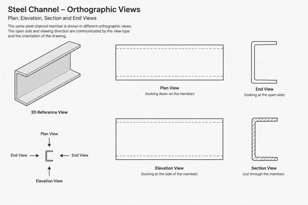
A single centerline in plan may not communicate this adequately. A section symbol, toe-direction note, offset dimension, or clearly modeled profile is often needed. End reversal must also be checked because local left and right can exchange even when the channel still appears to face the same general area in one view.
Angles
Angles require more information than a member line and shape designation. The long and short legs, heel, and toes must be oriented correctly. An unequal-leg angle can have several distinct placements around the same work line, and each placement changes the surfaces available for bolts or welds.
Useful orientation descriptions reference stable project geometry, such as “long leg vertical,” “long leg outstanding,” or “toe toward grid.” Informal phrases such as “angle facing left” are risky because left depends on the viewing direction.
Structural tees
For a structural tee, the stem direction is a primary orientation cue. The stem may point up, down, or sideways depending on the member’s function. Because plan views can conceal the stem, sections and elevations are often necessary to communicate placement.
Connection features should be checked against the actual flange and stem faces rather than inferred from the work line alone.
Rectangular and square HSS
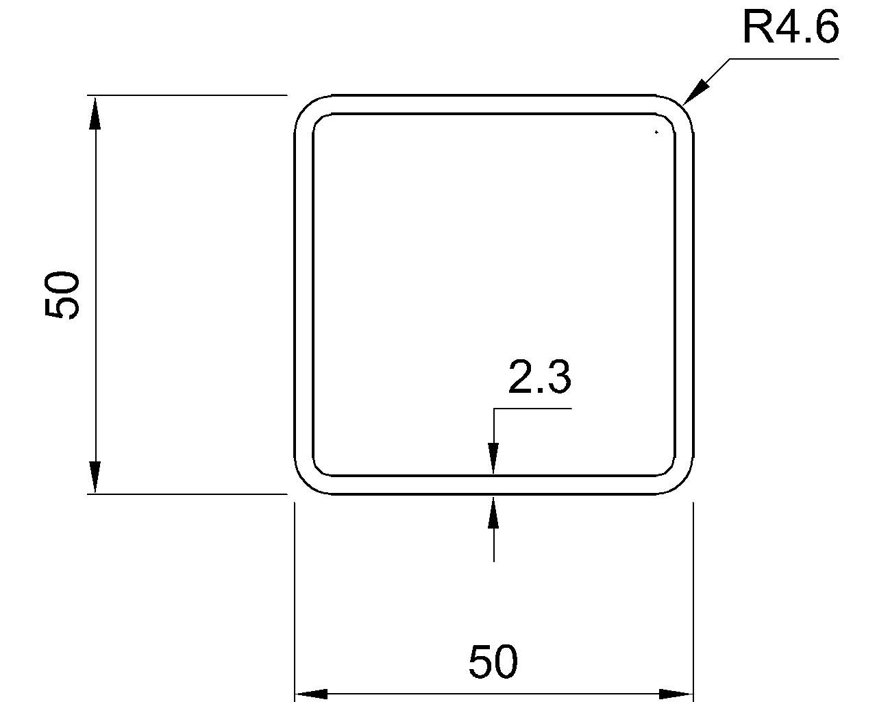
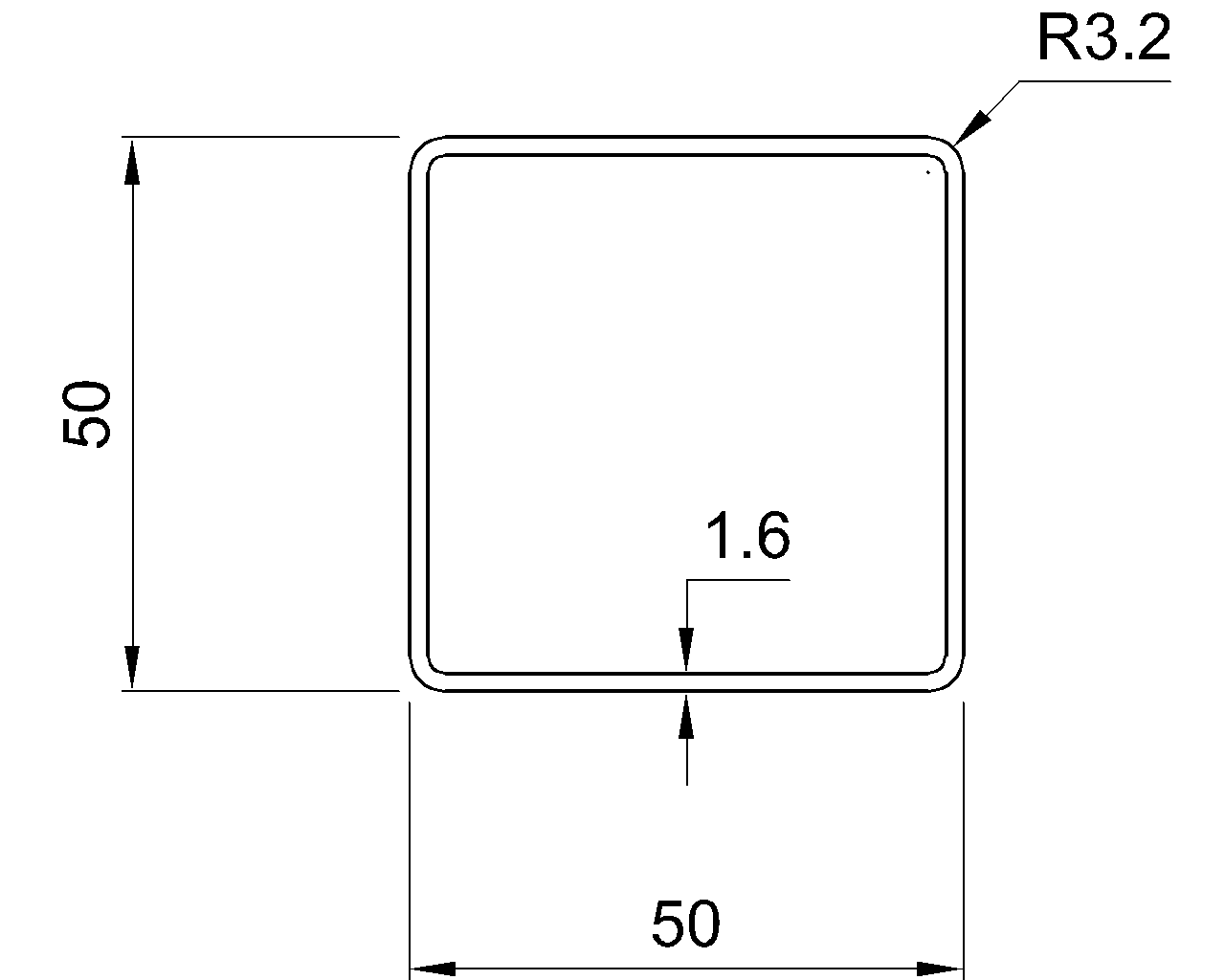
Rectangular HSS changes orientation when its wide and narrow faces are exchanged. That rotation affects connection faces, clearances, and the relationship between section properties and the applied loading directions.
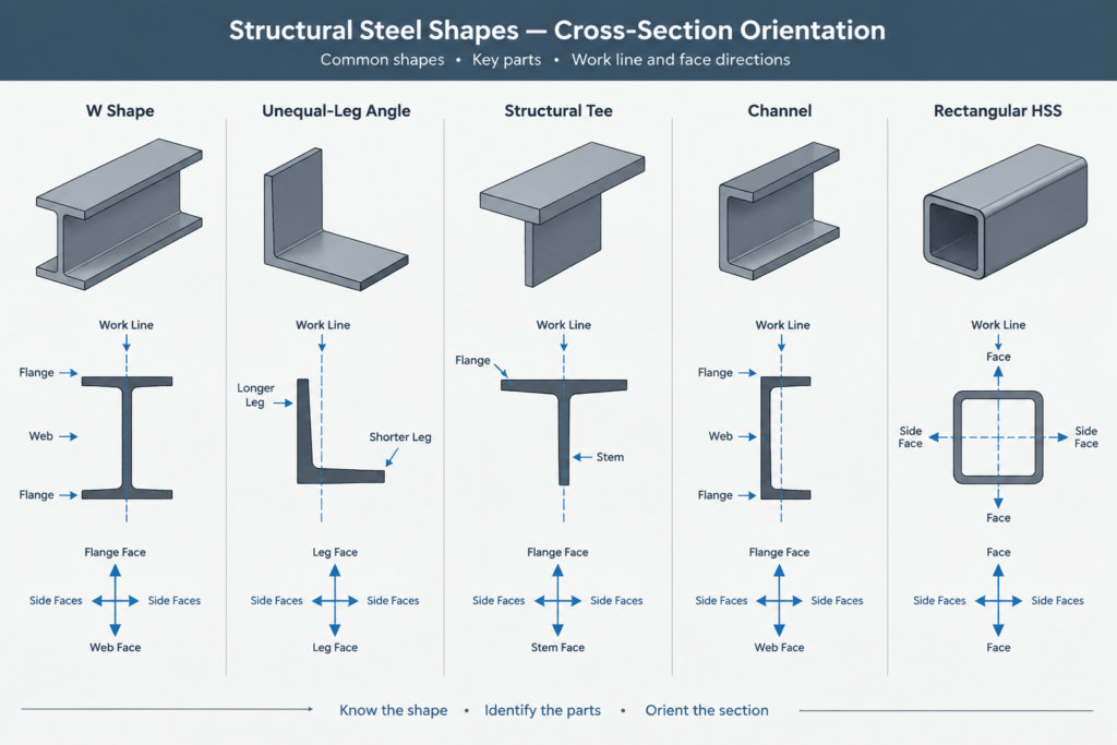
Square HSS may look unchanged after a quarter-turn, but fabricated features can reveal the difference. Holes, slots, cap plates, longitudinal seams, through-plates, and face-specific connections may require an identified orientation. A visually symmetric outline does not guarantee an interchangeable fabricated member.
HP shapes
HP shapes resemble wide-flange sections in drawings, but orientation remains important for splices, caps, embedded conditions, and attached components. The model should preserve the intended web and flange directions even if a simplified foundation or piling plan represents the member with a point or centerline.
How orientation appears in structural drawings
No single view reliably communicates every orientation condition. Good detailing combines views and references according to the complexity of the member.
- Plan views show skew, grid relationships, horizontal offsets, and the direction of open sections when enough profile information is visible.
- Elevations show slope, top and bottom relationships, end elevations, and vertical orientation.
- Sections provide the clearest confirmation of flange, web, leg, stem, or HSS-face direction.
- End views are useful for cross-section rotation, but their viewing direction must be identified.
- Isometric views can clarify complicated geometry, although they should support rather than replace controlled dimensions and orthographic views.
Near-side and far-side indications also depend on the stated viewing direction. A connection shown on the near side in one elevation may be on the opposite physical side when viewed from the other end.
A reliable CAD and modeling workflow
- Establish the work line. Confirm the intended start point, end point, and relationship to grids or support work points.
- Assign the correct section. Verify the shape family and designation before adjusting orientation.
- Display local axes. Use the model’s axis display or an equivalent diagnostic tool rather than relying only on shaded appearance.
- Set section rotation. Orient the web, flanges, legs, stem, or HSS faces relative to defined project references.
- Apply offsets deliberately. Distinguish a true member offset from a change in insertion point or profile justification.
- Check slope and skew independently. A correct plan angle does not prove that the end elevations are correct.
- Place connection geometry. Confirm that plates, bolts, welds, and cuts attach to the intended physical faces.
- Review multiple views. Inspect plan, elevation, section, and an end or isometric view before issuing drawings or exchanging the model.
Common orientation mistakes
- Using “left” and “right” without defining the viewing direction.
- Mirroring a member when the intended operation was end reversal, or reversing it when a mirror was required.
- Rotating the visible profile without checking local axes.
- Assuming a symmetric section makes attached features symmetric.
- Applying an offset in global coordinates when the detail requires a local section offset.
- Copying connections between members that have opposite start-end directions.
- Showing a channel or angle only as a centerline, leaving its open side unclear.
- Using a visually correct isometric view while plan, elevation, or section geometry remains inconsistent.
Practical orientation checklist
Before releasing a steel detail or model, verify the following:
- The member start and end agree with the project convention.
- The cross section is rolled to the intended position.
- Open sections face the correct direction.
- Long and short angle legs are identified where relevant.
- Rectangular HSS wide and narrow faces are correct.
- Slope and skew match the controlling geometry.
- Top, bottom, near-side, and far-side features agree across views.
- Offsets reference the intended work line or physical face.
- End-specific cuts and connections are assigned to the correct end.
- Model views and drawing views communicate the same physical member.
Steel member orientation should be treated as controlled geometric information, not as a cosmetic model setting. A shape designation tells the reader what section is used; orientation tells the fabricator and erector how that section occupies space. When work lines, local axes, viewing directions, and connection faces are all defined consistently, drawings become easier to interpret and downstream errors are less likely.