A steel column cap plate may look like a simple rectangular plate, but its detailing affects bearing, member elevation, weld access, erection, and the transfer of forces into the column. Ambiguity about the controlling elevation or plate location can shift the supported framing, while an incomplete understanding of the load path can produce details that are difficult to fabricate or assemble.
Cap plates occur on W-shape, HP, HSS, pipe, and built-up columns. They may support beams, girders, trusses, joists, equipment framing, or another fabricated assembly. The engineer must establish the required plate, welds, stiffening, and connection behavior. The detailer’s role is to convert that design intent into coordinated geometry without assuming that a generic closure plate or CAD block is structurally interchangeable with the specified cap plate.
What Is a Steel Column Cap Plate?
A column cap plate is a plate attached at or near the top of a steel column. Depending on the connection, it may provide a bearing surface, collect loads from supported framing, close the end of a hollow section, locate bolts, or create a practical interface between members with different widths and orientations.
The terminology is not always used consistently. A drawing may use cap plate, top plate, bearing plate, or closure plate. These descriptions should not be treated as automatic synonyms:
- Cap plate: A general term for a plate attached to the top of a column.
- Bearing plate: A plate intended to distribute a bearing force. Bearing plates can occur in locations other than column tops.
- Closure plate: A plate that closes an open HSS or pipe end, often for sealing, appearance, or protection. It may not be designed to receive a concentrated structural reaction.
- Connection plate: A plate whose primary function is to receive bolts, welds, or another connecting element.
One plate can perform several of these functions, but that must be confirmed from the design rather than inferred from its appearance.
Trace the Load Path Before Detailing the Plate
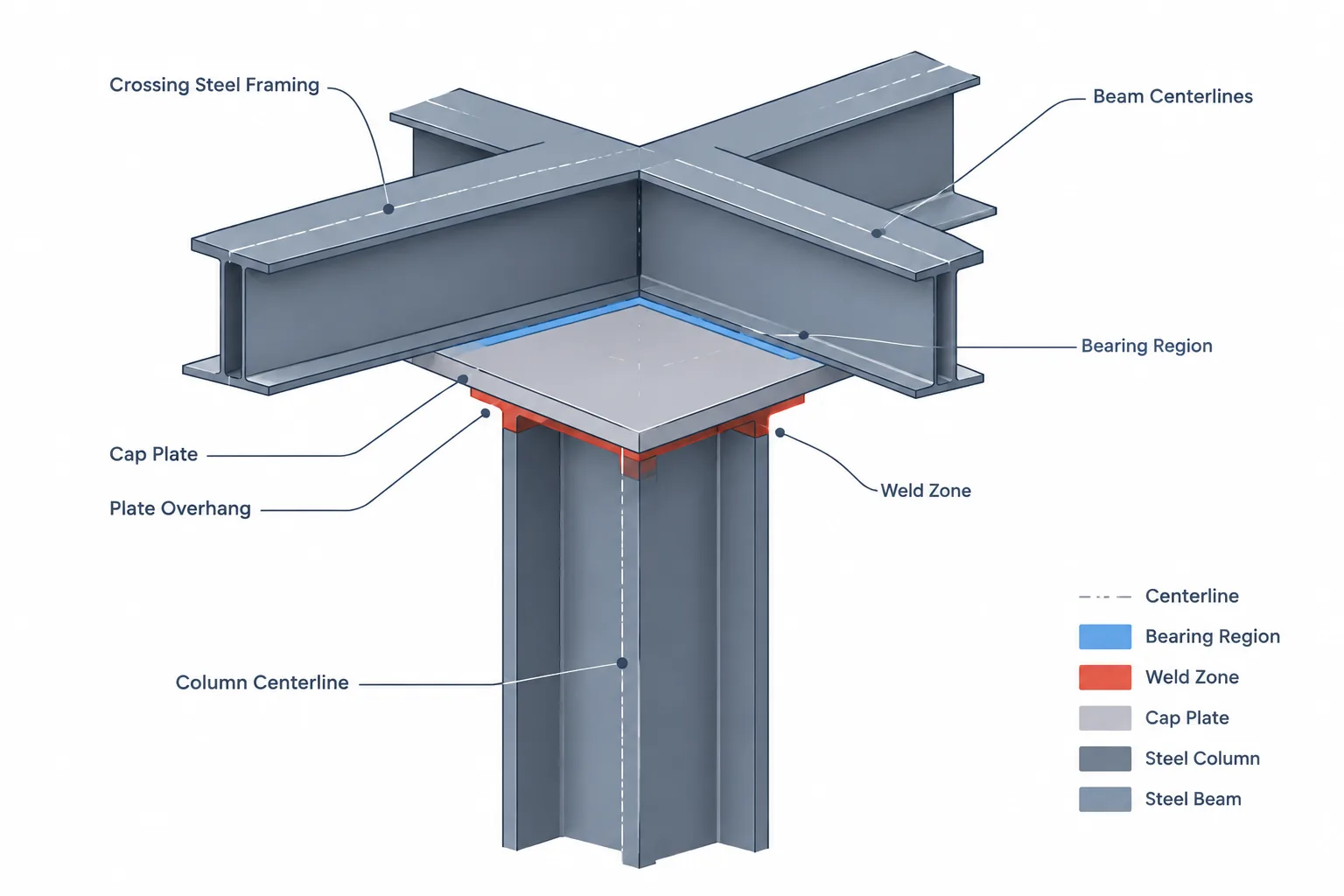
The first detailing question is not the plate’s outline. It is how the supported-member reaction reaches the column. A direct bearing condition may transfer compression through contact between the supported member and plate. The plate then distributes that force into the column walls, flanges, web, stiffeners, or other elements.
Other cap connections transfer shear, uplift, moment, or horizontal force through bolts and welds. Contact that appears to provide bearing in a model may not be the intended or reliable force-transfer mechanism. Conversely, a plate shown with bolts may still depend on direct bearing for part of the gravity load.
Identify the following before finalizing the detail:
- The member or assembly delivering the reaction.
- The intended contact or bearing region.
- The location where force enters the column cross-section.
- Whether uplift or lateral force must also be transferred.
- Whether stiffeners, diaphragms, continuity elements, or doubler plates are required.
- Whether erection bolts are part of the final structural connection or only assist assembly.
A wide plate over a narrow column does not automatically distribute load uniformly. Plate bending and the local response of the column still require engineering evaluation.
Establish the Controlling Elevation
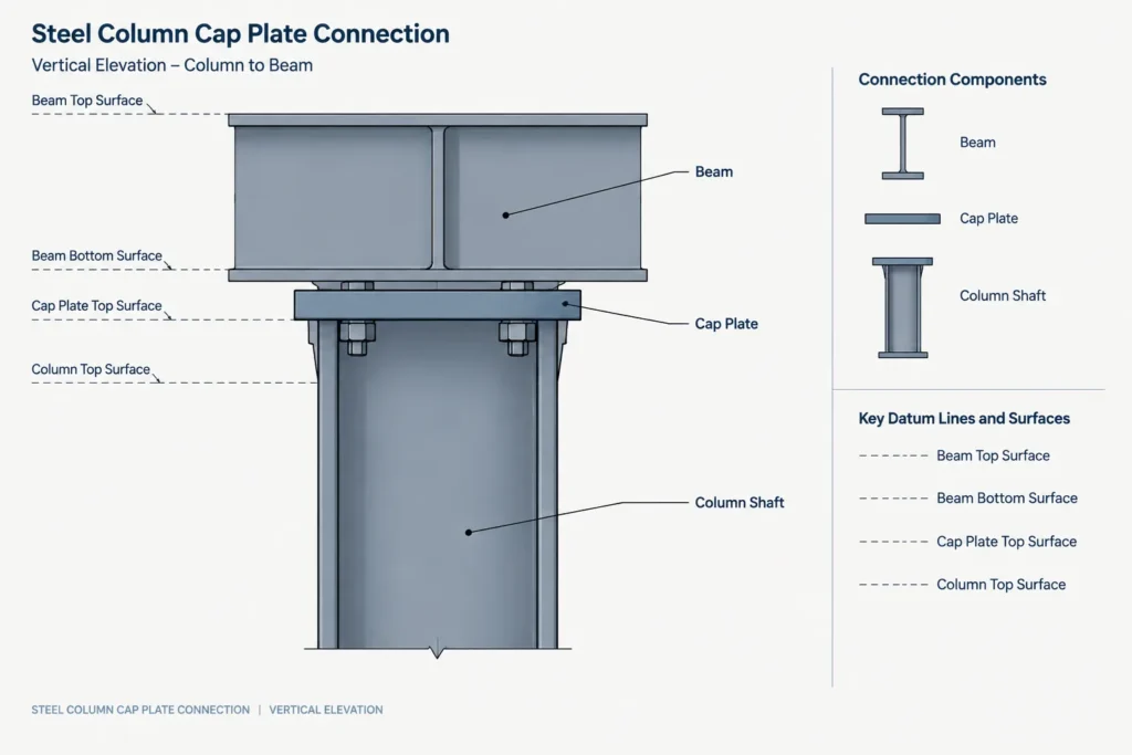
Cap plate details often create elevation mistakes because “top of steel” can refer to more than one surface. It may identify the top of the cap plate, the top of the column shaft before the plate is installed, or the top of the supported beam or girder.
The drawing set should make the controlling surface explicit. A useful elevation stack may include:
- Column work-point or reference elevation.
- Top of column shaft.
- Cap plate thickness and orientation.
- Top bearing surface.
- Supported-member depth or seat offset.
- Any shim, pack plate, finish, or field-adjustment zone included in the design.
Do not independently round or adjust one component of this stack. A small change to plate thickness, member depth, or bearing surface can alter the final framing elevation. When the architectural or structural drawing controls the top of the supported member, work backward through the complete stack to establish the column cut length.
Plan Datums and Plate Position
A cap plate should be located from stable datums rather than by a loose collection of edge dimensions. Common references include column centerlines, building grids, member work lines, web centerlines, and the centerlines of supported framing.
The column centroid is not always the correct layout origin. A cap plate may be intentionally eccentric because the supported member follows a grid line, wall line, or equipment axis. Channels, angles, and built-up columns can also have geometric references that differ from their centroidal axes.
| Detailing item | Useful controlling reference | Coordination concern |
|---|---|---|
| Plate location | Column or supported-member work lines | Intentional eccentricity must remain visible |
| Bolt holes | Hole-group centerlines or primary baselines | Match the mating member without relying on plate edges alone |
| Plate elevation | Designated bearing or top surface | Avoid conflicting top-of-steel interpretations |
| Column cut length | Established elevation stack | Account for the actual plate arrangement |
| Supported member | Its work line and bearing location | Check overhang, edge clearance, and erection access |
Open-Section and HSS Column Conditions
W-Shapes and HP Shapes
On an open I-shaped column, the plate crosses the flange and web region. The actual areas available to receive force and welds depend on the column orientation, flange width, web location, rolled fillets, and any stiffeners. A schematic drawing that represents the column as a plain rectangle can conceal interference near flange-to-web fillets or imply contact where none exists.
Plate holes, weld terminations, and attached parts should be checked against the real section geometry. If the plate must fit between or around other components, use verified shape data rather than a nominal-depth envelope.
HSS and Pipe Columns
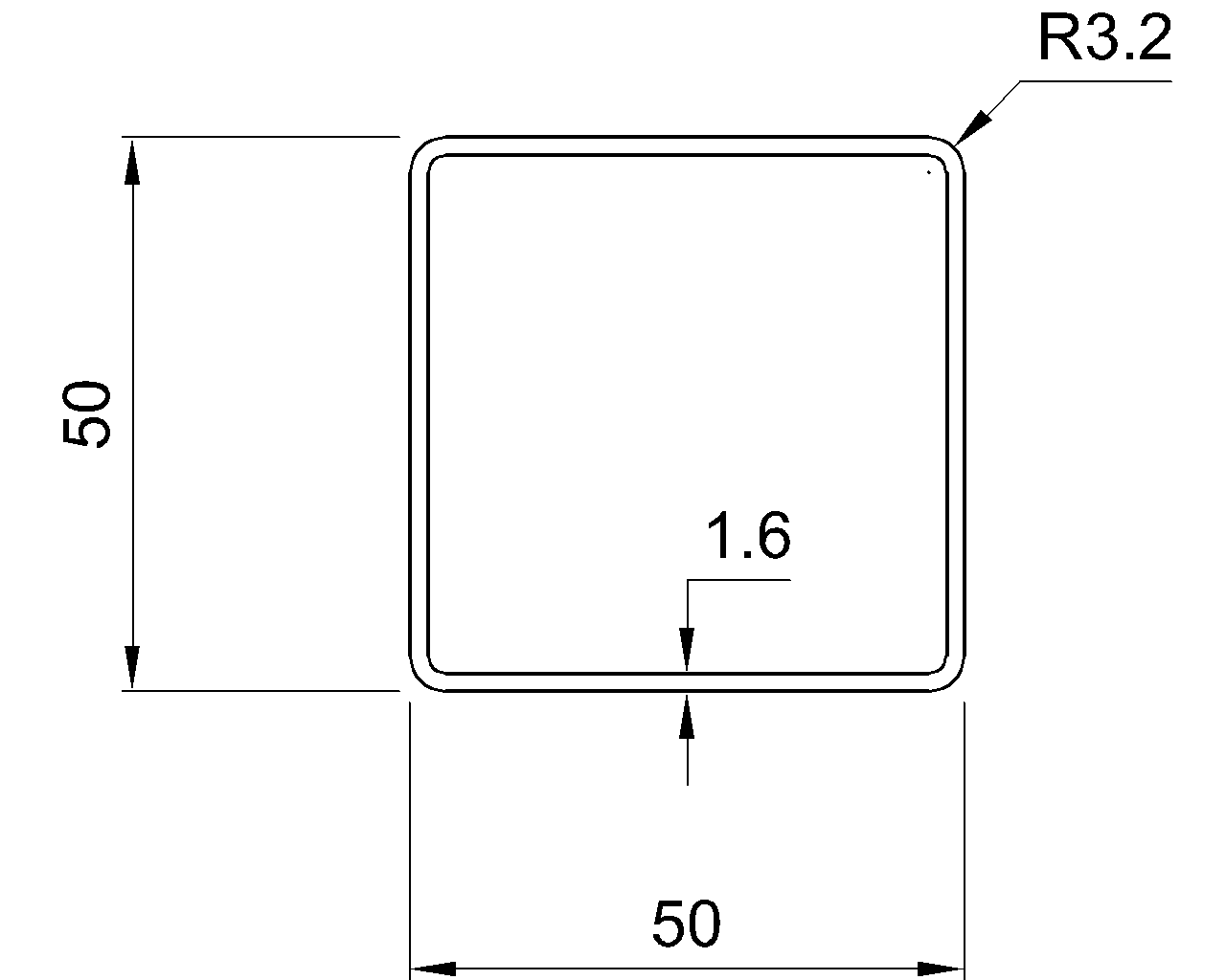
On an HSS column, load enters through the section perimeter unless internal diaphragms, through-plates, or other load-transfer elements are provided. The HSS corner radii reduce the length of truly flat wall available near the corners, and the weld seam may affect fabrication planning or appearance.
A plate matching the nominal outside dimensions of an HSS is not necessarily a flush-fitting closure detail. Actual corner geometry, weld preparation, plate edge position, and the desired weld configuration must be considered. If the plate projects beyond the HSS, the overhang can improve access but may create conflicts with adjacent framing or finishes.
Bearing Area, Plate Edges, and Supported-Member Fit
Show the supported member in plan when its position controls the plate. A centerline-only representation can hide partial bearing, flange overhang, skewed contact, or a collision between the member and cap plate attachments.
For sloped or skewed members, distinguish between the projected footprint and the actual contact surface. A sloped member end may require a shaped end, a beveled element, a seat, or another engineered transition. Do not assume that placing a sloped member on a horizontal plate creates the intended bearing condition.
Plate corners may also need attention. Square corners are easy to draw but can obstruct nearby welds, architectural components, deck edges, or intersecting members. Any clips, radii, chamfers, or special contours should be dimensioned from clear references and coordinated with fabrication methods.
Welds, Bolts, and Installation Access
The drawing must communicate where the cap plate is welded and which member receives each weld. A perimeter line in plan is not a substitute for a clear weld symbol and an appropriate section or elevation.
Check whether the specified weld is physically accessible around the column. Adjacent beams, stiffeners, connection plates, and plate overhang can block the welding path or inspection view. For a shop-attached cap, the fabrication sequence may determine which welds remain accessible after other parts are added.
When the supported assembly is bolted to the cap plate, model the entire fastener zone rather than only the holes. Review bolt insertion direction, washer and nut space, wrench access, hole alignment, and conflicts with the column below. A hole that clears the column wall in plan can still place a nut or tool against the wall, flange, or weld.
What to Show on Shop and Erection Drawings
A complete cap plate detail commonly needs more than a plate callout. Depending on the connection, the drawing should communicate:
- Plate mark, material designation, thickness, and overall geometry.
- Column orientation and the relationship to grids or work lines.
- Controlling top and bottom elevations.
- Plate offsets from meaningful centerlines.
- Hole size, type, quantity, and layout as specified by the design.
- Weld locations and which connections are shop or field work.
- Supported-member orientation and intended bearing region.
- Required stiffeners, diaphragms, closure elements, or connection plates.
- Field-clearance, erection, and tool-access considerations.
Use sections where a plan view cannot show the elevation stack or load-transfer geometry. Avoid repeating the same controlling dimension in several views, especially if later revisions could make those dimensions disagree.
A Practical Coordination Checklist
- Confirm whether the plate is structural, a closure, or both.
- Trace the intended load path into the column section.
- Identify the controlling elevation and calculate the complete elevation stack.
- Verify the exact column shape, orientation, and real section geometry.
- Locate the plate and holes from stable work lines or baselines.
- Show the supported member’s actual footprint and orientation.
- Check bearing, overhang, edge conditions, and nearby clashes.
- Review weld access and the likely fabrication sequence.
- Review bolt installation and tightening access where applicable.
- Coordinate stiffeners, diaphragms, and other internal or external reinforcing elements.
- Make shop-versus-field responsibilities clear.
- Escalate unexplained eccentricities or incomplete load-path information for engineering clarification.
Keep the CAD Model Connected to Design Intent
A reusable cap plate block or parametric component can speed production, but it should not become the design authority. Its insertion point, plate outline, holes, and default weld representation must be checked for each connection. Shape substitutions, section rotations, and plate-thickness changes can alter elevations and clearances even when the plan location remains unchanged.
The best cap plate details connect three things clearly: the structural load path, the controlling geometric datums, and the practical fabrication sequence. When those relationships are visible, the plate becomes more than a rectangle at the top of a column—it becomes a coordinated interface between design, shop work, and field erection.