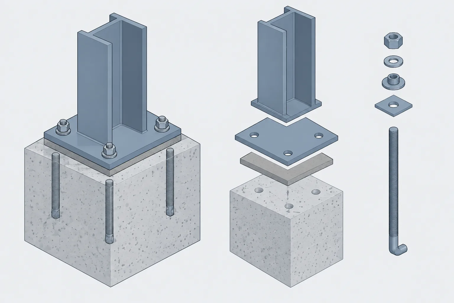
A steel column base plate rarely bears directly on a perfectly level concrete surface at the moment the column is erected. Some form of adjustment is normally needed to establish the column elevation, provide temporary support, and allow the erector to plumb the member before the space below the plate is grouted.
For drafters and designers, the important issue is not merely showing a base plate above concrete. The drawings must communicate how the elevation is controlled, what occupies the space beneath the plate, and whether the selected leveling arrangement is compatible with the anchor rods, grout placement, erection sequence, and final load path.
This guide explains the geometry and coordination questions behind common base plate leveling methods. It does not select a method for a project; that decision must follow the structural design, project specifications, erection plan, and responsible engineer’s requirements.
Why a Grout Gap Is Commonly Shown
The top of a concrete pedestal or foundation is subject to construction variation and may not provide uniform bearing over the full base plate. A planned space between the concrete and steel gives the erector room to set the column at the required elevation and permits grout to be placed beneath the plate.
Once properly installed and accepted, the grout creates a bearing interface between the base plate and the supporting concrete. It can fill local surface irregularities and distribute compression over the intended bearing area. Grout should not be treated in the model as an unexplained empty offset. It is part of the base condition and affects elevations, anchor rod projection, plate access, and erection details.
The required gap is project-specific. It should come from the contract documents, approved details, or direct coordination rather than from a drafter’s default CAD standard.
Common Base Plate Leveling Methods
Several arrangements can establish the base plate elevation. Each changes what must be shown and checked.
Shim Packs
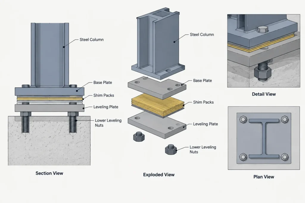
Steel shims may be placed on the concrete beneath selected areas of the plate. The column is lowered onto the shim packs, adjusted as permitted by the erection procedure, and later grouted.
On drawings, a generic note such as “shim as required” may be insufficient when the location of the shims matters. Shim packs near plate edges can interfere with grout flow, while packs located under heavily loaded regions may affect bearing behavior before and after grouting. Whether shims remain permanently in place must also be consistent with the project requirements.
Leveling Plates
A leveling plate is a separate plate installed before the column assembly. It can provide a prepared bearing surface and a controlled elevation for the main base plate. Depending on the design, it may be grouted or otherwise supported before the column is set.
Detailers should clearly distinguish the leveling plate from the column base plate. Separate part identification, plan dimensions, thickness, holes, orientation, elevation, and installation sequence may be needed. If both plates appear as overlapping rectangles in plan, sections and labels become especially important.
Leveling Nuts
Some base plates are temporarily or permanently supported on nuts installed below the plate on the anchor rods. Turning the nuts provides direct elevation adjustment at the rod locations.
This method should never be assumed merely because there appears to be room for a lower nut. Supporting a plate on nuts can introduce concentrated reactions and can affect anchor rod behavior, plate bending, washer requirements, grout placement, and the erection load path. The arrangement must be intentionally designed and documented.
The detail should make clear which nuts are below the plate, which are above it, and whether lower hardware remains after grouting. A section through the anchor rod is usually more informative than a plan symbol alone.
Leveling Screws or Other Adjustment Devices
Some assemblies use leveling screws, threaded devices, or proprietary adjustment systems. These require explicit details rather than a generic base plate note. The drawings should identify device locations, required plate features, access for adjustment, and the condition after grout placement. Product-specific requirements should be verified from approved project information rather than inferred from a similar detail.
Geometry That Must Be Coordinated
Top of Concrete and Base Plate Elevations
The controlling vertical references should be unambiguous. A detail may identify the top of concrete, bottom of base plate, top of base plate, and column work point, but these elevations should not conflict with one another.
If the base plate thickness or grout gap changes, the column elevation can change unless another dimension is adjusted. A useful CAD check is to reconstruct the vertical stack from the controlling datum:
- Top of concrete or pedestal elevation
- Specified grout or leveling space
- Base plate thickness
- Column end position relative to the plate
- Column work point or framing elevation
Redundant dimensions can help readers, but one reference should control. Derived elevations should agree with the modeled geometry.
Anchor Rod Projection
Anchor rod projection must accommodate the complete assembly, not just the base plate thickness. The stack may include a grout gap, lower leveling hardware, the plate, washers, upper nuts, and any required thread extension.
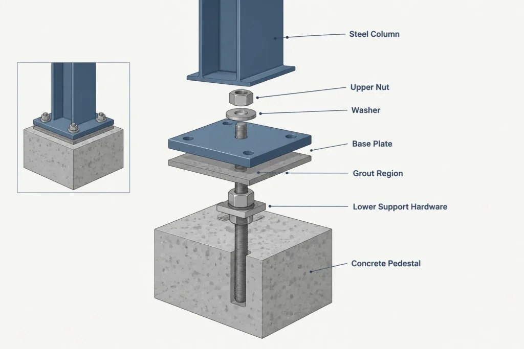
A change in leveling method can therefore make an otherwise unchanged anchor rod detail invalid. For example, replacing shims with lower nuts adds hardware beneath the plate and changes where the plate sits along the threaded portion. Rod projection and thread location should be rechecked rather than copied from the previous condition.
Base Plate Hole Size and Rod Position
Base plate holes provide assembly clearance, but they do not eliminate the need to coordinate actual rod location, available adjustment, washers, and plate edges. The leveling method must work even when the rod is not perfectly centered in the hole.
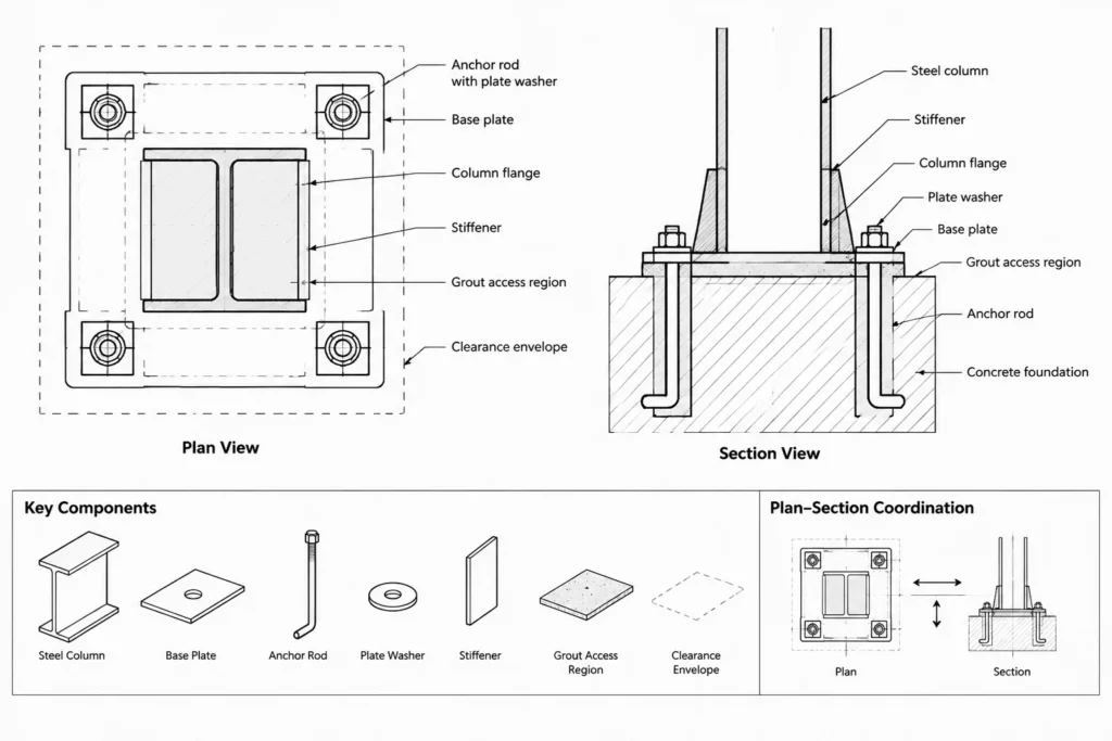
Large washers or plate washers can overlap welds, stiffeners, column flanges, leveling devices, or grout holes. A plan view should show the hardware envelope where congestion is likely.
Grout Placement and Flow
Grout must be able to reach the intended region beneath the plate. Plate size, stiffeners, shear elements, shim locations, and edge formwork can create isolated pockets or obstruct flow.
Large or congested plates may require planned placement access, grout holes, venting provisions, or a defined installation sequence. These features should only be added when required and coordinated; a grout hole is not a universal base plate feature. Its location must avoid the column footprint, welds, anchors, stiffeners, and critical plate regions.
Comparison of Leveling Arrangements
| Method | Primary drafting concern | Coordination question |
|---|---|---|
| Shim packs | Show or note permitted support locations | Do the shims interfere with grout flow or bearing? |
| Leveling plate | Separate the two plates in plans, sections, and marks | How is the leveling plate installed and supported? |
| Leveling nuts | Show the full hardware stack and thread relationship | Has support on the anchor rods been structurally addressed? |
| Adjustment devices | Detail holes, access, and final disposition | Are product and installation requirements verified? |
What a Useful Base Plate Section Should Show
A section through the column base is often the clearest place to communicate the leveling condition. Depending on the project, it may show:
- The column and its relationship to the base plate
- Base plate thickness and orientation
- Top of concrete or pedestal datum
- The intended grout region
- Shim, leveling plate, nut, or adjustment-device location
- Anchor rod, washer, and nut arrangement
- Welds, stiffeners, or shear-transfer components
- Relevant elevations and controlling dimensions
The drawing does not need to depict every grout surface irregularity. It should show enough information to define the intended assembly without implying unrealistic contact or an unsupported erection method.
CAD Modeling and Detailing Workflow
A reliable workflow begins by modeling the concrete reference surface and base plate as separate objects. Avoid placing them coincident and later adding a grout note; that approach can hide elevation errors in sections and material coordination.
-
Establish the controlling datum. Confirm whether the model is driven from top of concrete, bottom of plate, top of plate, or a column work point.
-
Model the intended separation. Represent the specified space between concrete and plate without choosing an unapproved value.
-
Add the actual leveling concept. Show shim zones, a leveling plate, lower nuts, or other devices only when that method is confirmed.
-
Build the anchor hardware stack. Check plate thickness, washers, nuts, thread region, projection, and access together.
-
Review plan and section views. Plan views reveal clashes around the column and rods; sections reveal elevation and hardware-stack problems.
-
Check related sheets. Compare the steel detail with foundation plans, anchor rod plans, schedules, erection drawings, and project notes.
For simplified models, grout may be represented as a bounded region or noted gap rather than a detailed solid. The representation should still produce correct elevations and should not clash with lower hardware.
Frequent Drawing and Coordination Problems
- Undefined empty space: The plate is drawn above concrete, but no grout or leveling method is identified.
- Conflicting elevations: Top-of-concrete and top-of-plate elevations do not match the plate and gap dimensions.
- Copied anchor projection: Rod geometry is reused after the plate thickness or leveling method changes.
- Ambiguous nut placement: A section shows multiple nuts without identifying which are leveling and which secure the final assembly.
- Hidden interference: Washers, stiffeners, welds, and column flanges overlap in plan.
- Uncoordinated grout holes: Openings are added as drafting conventions without checking structural and fabrication implications.
- Assumed field adjustment: Notes imply that the erector can alter shims, nuts, or rod positions without defined limits or approval.
Practical Review Checklist
Before issuing a base plate detail, verify that:
- The leveling method is identified or referenced to confirmed project information.
- The grout space agrees with all controlling elevations.
- The anchor rod projection fits the entire hardware and plate stack.
- Lower nuts or adjustment devices are shown only when intentionally required.
- Washers and tools have physical clearance from the column and stiffeners.
- Shim or leveling-plate geometry does not create unexplained conflicts.
- Grout placement access has been considered for congested plates.
- Plan, section, foundation, and erection information describe the same condition.
- Any change to plate thickness or elevation triggers a new rod and hardware review.
Steel column base plate leveling is an erection, geometry, and load-path issue—not merely a gap drawn beneath a plate. Clear datums, an intentional leveling method, and a coordinated anchor hardware stack help turn a schematic base detail into information that can be fabricated and erected without avoidable ambiguity.