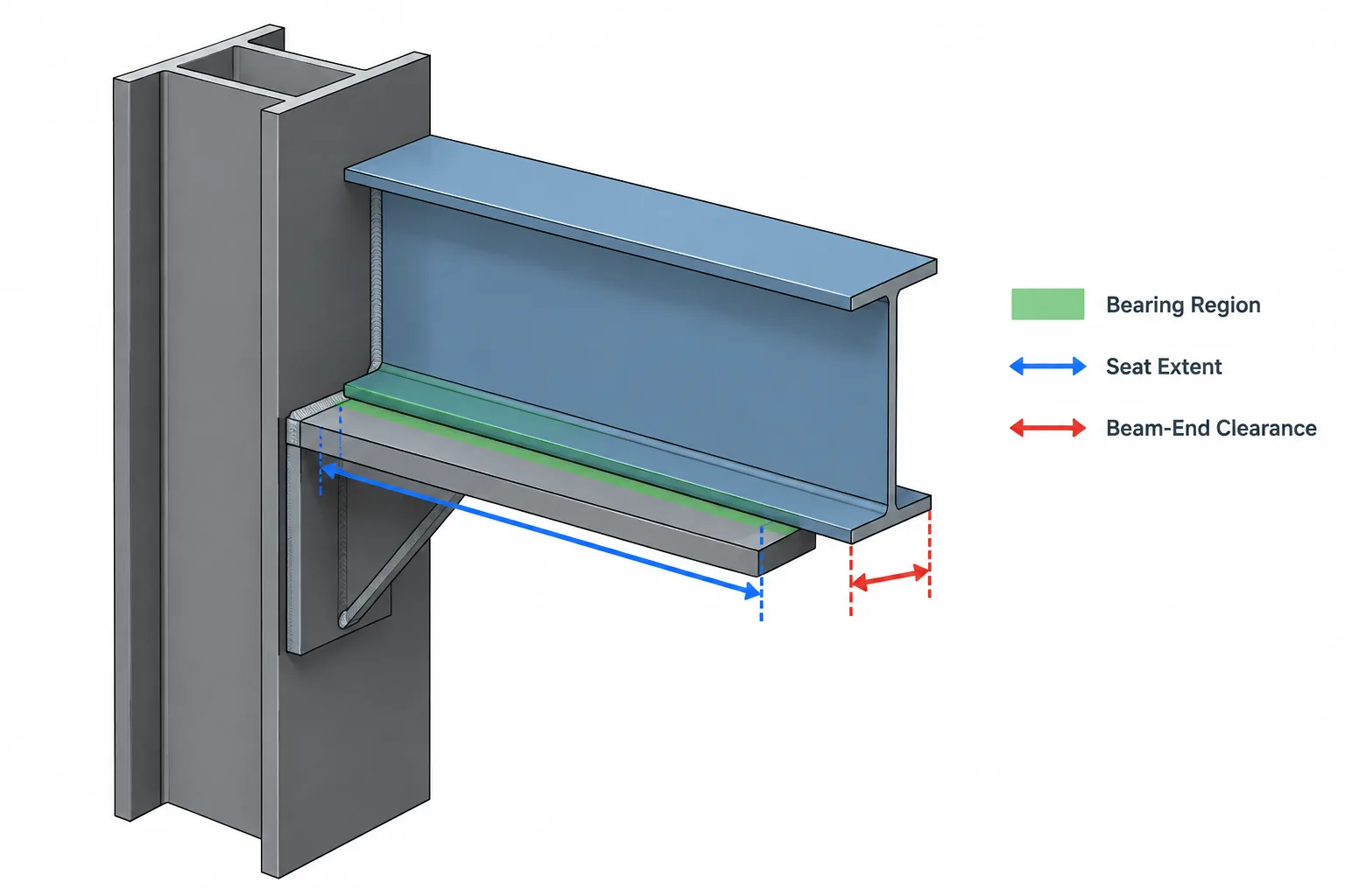
A beam end resting on a wall, girder, seat angle, cap plate, or bearing plate may look simple in elevation. In practice, several different dimensions control the interface. The steel beam bearing length describes the portion of the member or bearing assembly that transfers reaction to the support. Seat length describes the available supporting surface. End clearance provides space between the beam end and an adjacent obstruction.
These terms are related, but they are not interchangeable. Treating them as one dimension can produce a beam that lacks the intended bearing, conflicts with the supporting construction, or cannot be erected as drawn. Designers and detailers should identify which dimension controls the structural load path, which controls fit, and which remains available for field adjustment.
What Is Steel Beam Bearing Length?
Bearing length is the longitudinal extent over which a beam reaction is delivered to its support. The exact load-transfer interface depends on the framing condition. A beam may bear directly on a plate, rest on a fabricated seat, frame over the flange of another steel member, or transfer load through an end plate or other connection component.
The visible overlap in a drawing is not always the effective bearing length. For example, part of a seat may extend beyond the beam, or the beam may be held away from a wall face while a plate beneath it continues farther into the support. The structural design documents and connection design criteria should establish the required load path and bearing condition.
Bearing length can affect more than the supporting material. Depending on the detail, the designer may need to consider the supported beam web, flange behavior, stiffening, bearing plate behavior, supporting member, welds, anchors, masonry, or concrete. A CAD model can confirm geometry, but it cannot determine whether the resulting bearing condition is structurally adequate.
Bearing Length vs. Seat Length vs. End Clearance
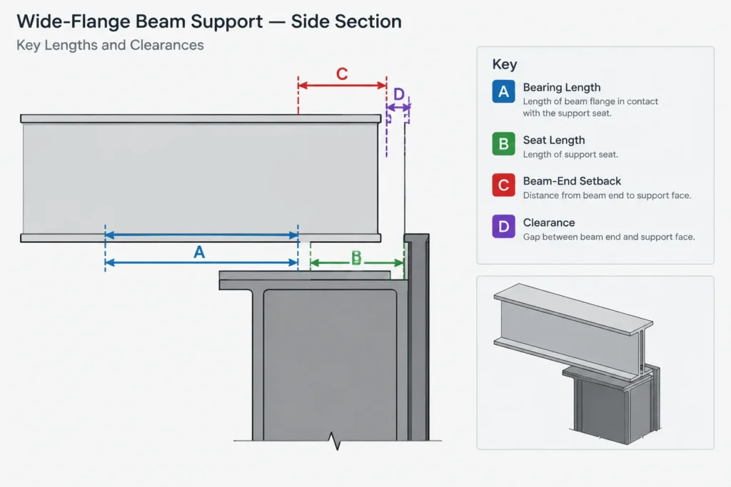
| Term | What it describes | Primary coordination concern |
|---|---|---|
| Bearing length | The longitudinal region through which the supported member delivers its reaction | Structural load transfer and local behavior |
| Seat length | The physical length of the supporting surface available beneath the member | Fit, connection geometry, weld access, and erection |
| End clearance | The gap between the beam end and a wall, column, plate, stiffener, or other obstruction | Erection access, tolerances, and clash avoidance |
| Member overlap | The plan or elevation projection of the beam across the support boundary | Geometric reference only; it may not equal effective bearing |
| End setback | The distance from a work point, grid line, support centerline, or reference face to the member end | Member length and placement |
A seat normally must provide enough usable surface for the intended bearing while also accommodating erection and fabrication considerations. That does not mean its total length should automatically be labeled as bearing length. Likewise, a beam end setback may establish where the member stops without directly stating how much of the beam is supported.
Why End Clearance Must Be Shown Separately
End clearance is commonly needed so a beam can be lowered, swung, or slid into position without striking adjacent construction. It can also prevent unintended contact with a column flange, wall, stiffener, embed plate, or the end of another member.
A zero-gap CAD model may appear precise but can be impractical. Real steel and supporting construction are subject to permitted variation, and erected members need an installation path. Conversely, adding an arbitrary gap can reduce the intended overlap or create a mismatch with connection plates. Clearance should therefore come from the project details, connection requirements, and erection approach rather than a drafter’s default.
Where the beam end is close to a wall or other concealed surface, dimension the gap to an identifiable face. Avoid relying on a line that could represent finish, structural concrete, masonry, fireproofing, or a schematic wall boundary.
Common Beam-Bearing Conditions
Beam on a steel seat
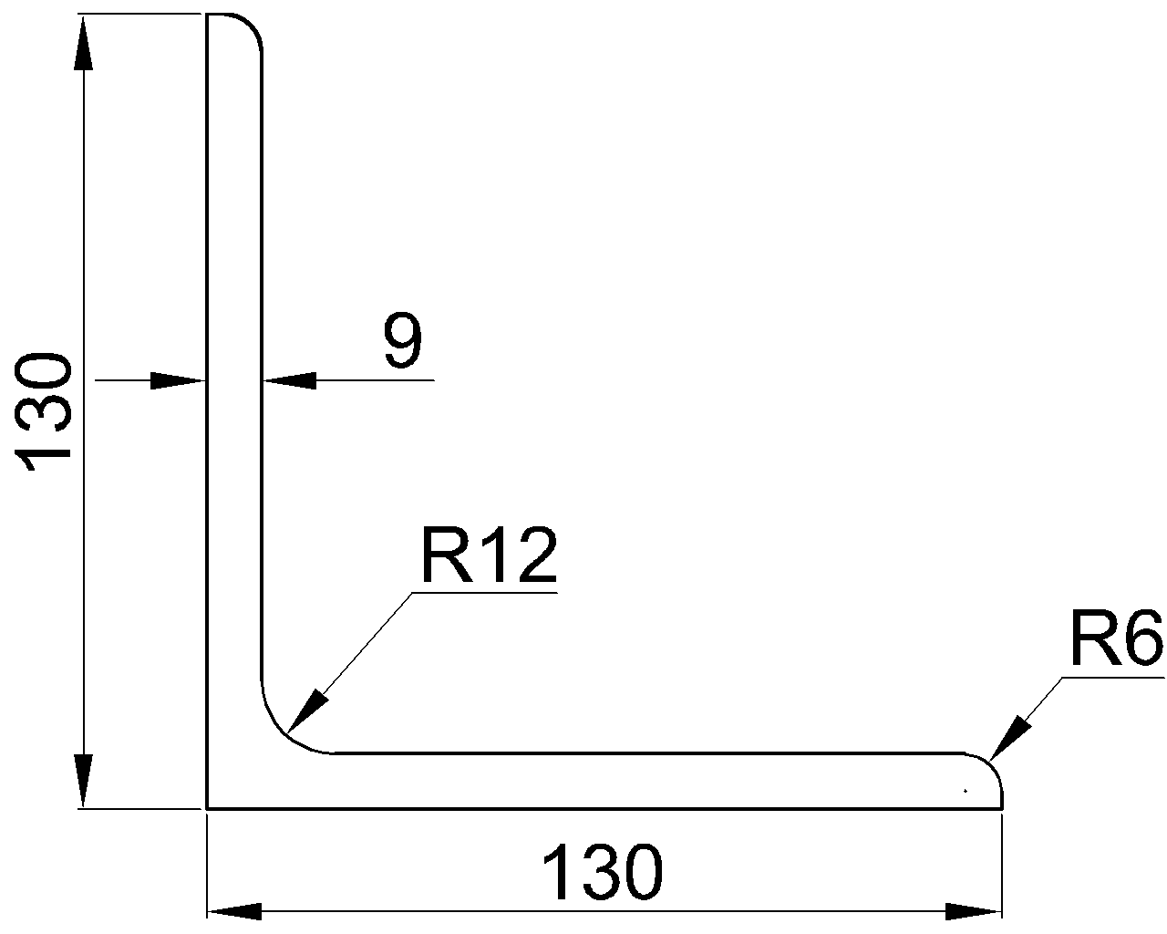
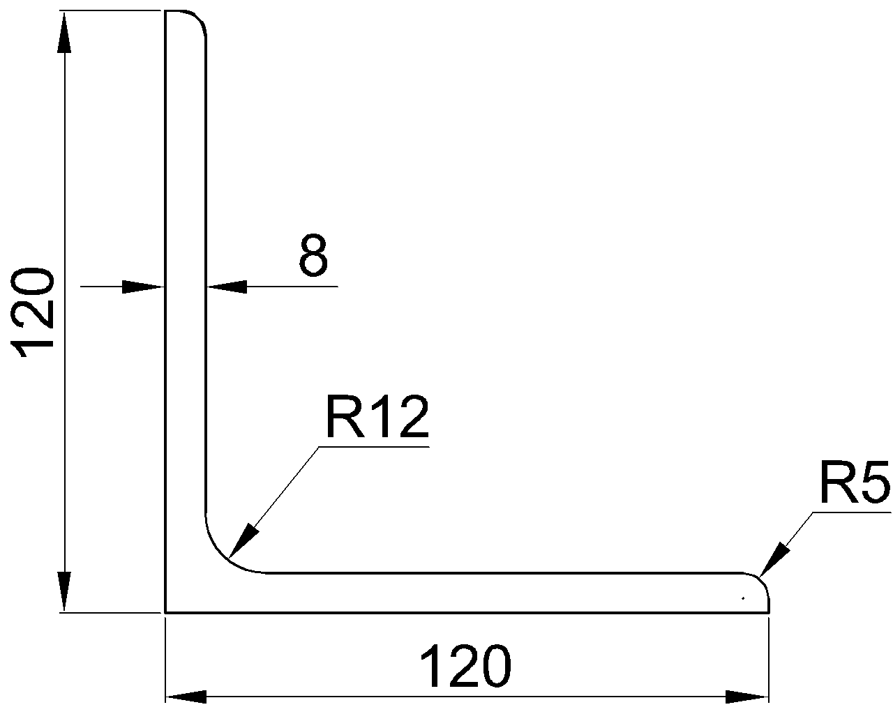
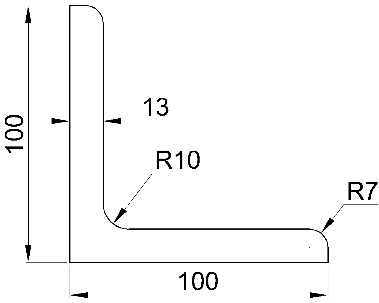
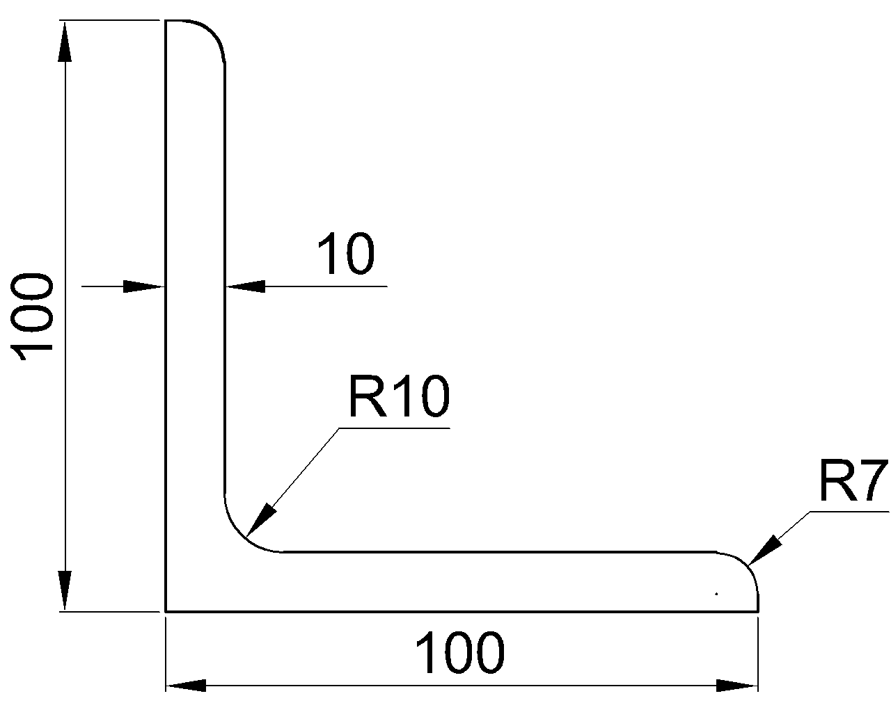
A seated connection may use an angle, plate, tee, or fabricated bracket beneath the beam. The detail should distinguish the beam-end location from the outer edge of the seat. Check the usable seat surface after accounting for welds, radii, stiffeners, bolts, and any erection clearance. If the connection includes a top attachment or stabilizing component, verify that its hole and edge geometry remain compatible with the beam position.
Beam on a girder or column cap
When a beam bears over a flange or cap plate, the support centerline alone may not define the member end. The detail may be controlled by a grid line, column centerline, face of column, edge of plate, or work point. Confirm which reference governs before calculating member length. Also check whether multiple beams share the supporting surface and whether their ends require separation.
Beam at masonry or concrete
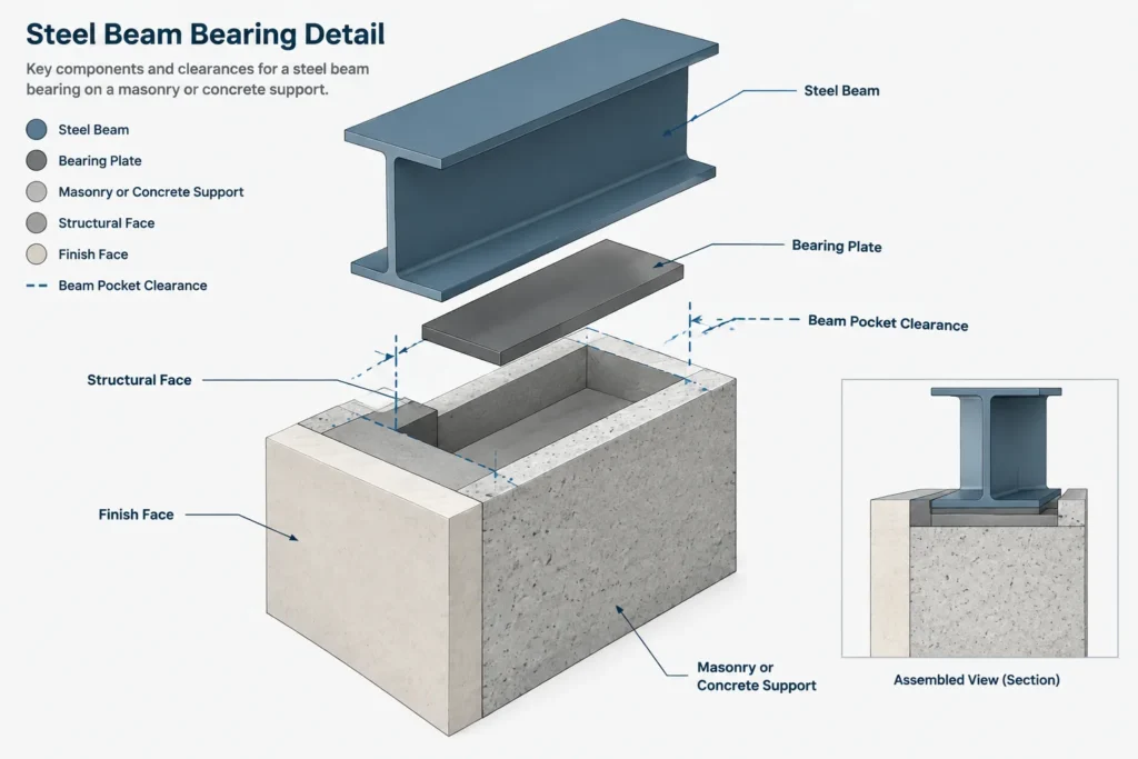
A steel beam supported by masonry or concrete often bears through a separate plate. The plate distributes load and may extend beyond the beam in one or more directions. As a result, beam bearing, plate embedment, pocket depth, and beam-end clearance are different dimensions. Coordinate the structural face of support rather than assuming that an architectural finish line defines the bearing boundary.
Sloped or skewed beam bearing
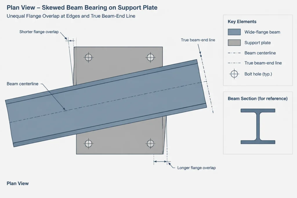
For a sloped beam, horizontal overlap and contact length along the member are not necessarily the same. For a skewed beam, the end cut may create different overlap at each flange edge. A plan dimension alone may therefore be insufficient. Use a section, enlarged plan, or true-orientation view to show the governing geometry clearly.
A Reliable CAD and Detailing Workflow
- Identify the load-transfer surface. Determine whether the beam reacts on a seat, plate, flange, wall, or connection assembly.
- Establish governing references. Locate grid lines, work points, support centerlines, structural faces, and top-of-steel elevations before trimming the member.
- Model the supporting component. Include the actual plate, seat, flange, or bracket geometry instead of stopping the beam at a schematic support line.
- Place the beam end independently. Apply the specified setback or clearance rather than forcing the member end to coincide with a support edge.
- Check usable bearing. Review the overlap that remains after end cuts, skew, weld clearance, radii, stiffeners, and nearby connection elements are considered.
- Test the erection path. Consider how the member reaches its final position and whether neighboring steel or construction blocks installation.
- Dimension from stable references. Use structural faces, work points, or member centerlines that can be identified consistently in plans, sections, and shop drawings.
- Flag unresolved criteria. Do not infer a required bearing length or modify a designed connection solely to make the model fit.
Drawing Practices That Reduce Ambiguity
- Label bearing, seat, setback, and clearance dimensions according to their actual function.
- Show a section through the support when plan overlap does not explain the load path.
- Dimension beam ends to a defined structural reference rather than to an unverified CAD outline.
- Indicate whether a dimension is horizontal, vertical, along the member, or normal to a support face.
- Show bearing plates and seat components as separate objects with separate piece identification where applicable.
- Coordinate architectural finishes, fireproofing, grout, and nonstructural enclosures without treating them as structural bearing surfaces.
- Avoid scaling drawings to obtain missing bearing or clearance requirements.
Frequent Coordination Errors
Using seat length as the bearing length: A portion of the seat may be unavailable because of connection geometry or because it projects beyond the beam.
Measuring to the wrong wall face: Finish faces, nominal wall lines, and structural support faces can occupy different locations.
Ignoring skew: A skewed end may have adequate overlap at one edge and insufficient overlap at another.
Letting the model choose the detail: Automatic trimming and connection tools can create clean geometry without preserving the intended load path or erection clearance.
Changing clearance without reviewing member length: Moving the beam end changes its fabricated length and may affect holes, plates, stiffeners, or connections at the opposite end.
Final Review Principle
The key question is not simply, “How far does the beam overlap the support?” A complete review asks where the reaction is transferred, how much supporting surface is usable, where the fabricated beam end is located, and what space is needed to erect the member. Keeping bearing length, seat length, end setback, and end clearance separate makes drawings easier to interpret and helps expose coordination problems before fabrication.