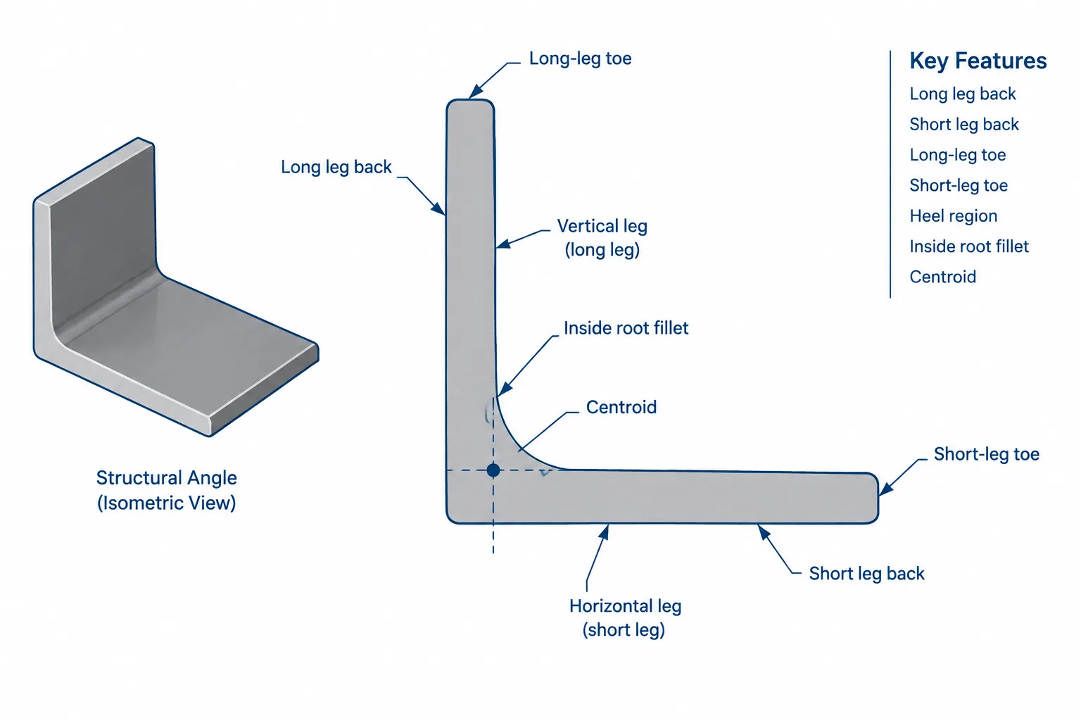
A rolled steel angle looks simple: two perpendicular legs with a specified thickness. Its actual cross-section, however, is not made entirely of sharp rectangular edges. The leg junction contains a root fillet, the free ends have rounded toes, and the centroid does not lie at the geometric center of the overall leg envelope. These details affect how angles are identified, placed, dimensioned, and checked in CAD.
Understanding steel angle heel and toe terminology is particularly important when laying out bolt lines, fitting plates against an angle, modeling clearances, or comparing a simplified CAD profile with published shape properties. The goal is not to dimension every rolled radius on a shop drawing. It is to know which geometric features control the work and which should remain reference information.
Basic parts of a structural steel angle
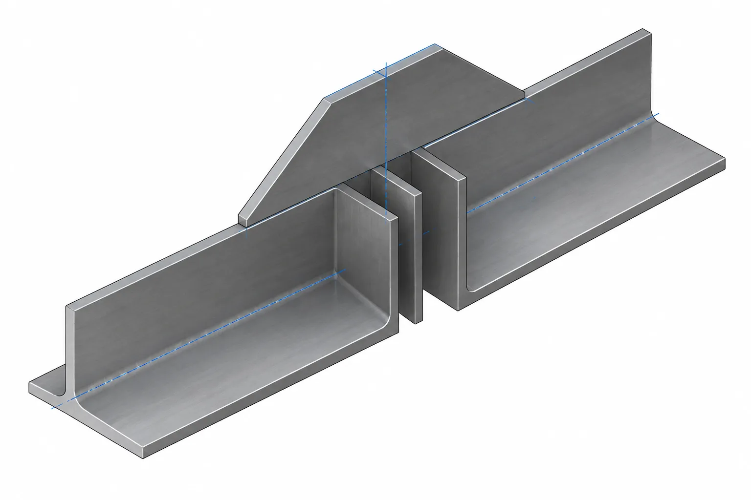
An angle has two legs meeting at approximately a right angle. Equal-leg angles have the same nominal leg size in both directions, while unequal-leg angles have a long leg and a short leg. Common geometric terms include:
| Term | Practical meaning | Why it matters |
|---|---|---|
| Back of leg | The outside planar surface of an angle leg | Frequently used as a fabrication, fit-up, and placement datum |
| Heel | The region where the two legs meet | Establishes orientation and contains the root fillet |
| Root radius | The inside fillet formed at the junction of the legs | Limits how closely another part can fit into the inside corner |
| Toe | The free end of either leg, opposite the heel | Defines the open edges and affects edge-clearance interpretation |
| Toe radius | The rounded profile at a free leg edge | Matters for close fits, scans, and detailed section profiles |
| Thickness | The nominal thickness of the rolled legs | Used for identification, connection layout, and section modeling |
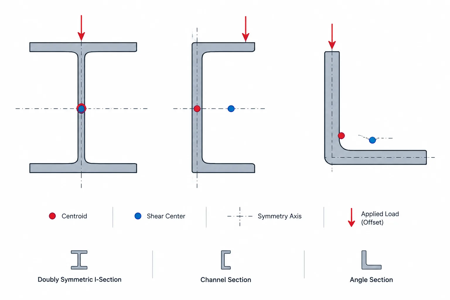
| Centroid | The area-balanced location of the cross-section | Usually offset from both backs and from the center of the bounding box |
The word heel describes a region rather than a single universally dimensioned point. In layout work, drafters often use the theoretical intersection of the two outside back planes as a stable geometric reference. That constructed point is not the same as the visible inside edge of the root fillet.
Root radius versus the theoretical heel
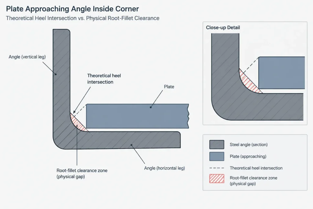
If the two back-of-leg planes are extended until they intersect, they form a sharp theoretical corner. This intersection is useful as a CAD origin and dimensional datum because it remains easy to construct even when the rolled profile includes fillets and rounded edges.
The inside surface is different. Material transitions between the legs through a curved root fillet. A plate, washer, bolt head, weld backing element, or other component cannot occupy the theoretical sharp inside corner because steel is physically present there. A detail that appears clear when the angle is drawn as two sharp-edged rectangles may clash with the actual rolled fillet.
This distinction produces two separate questions:
- Where is the angle located? The backs or their theoretical intersection may provide the clearest placement datum.
- What physically fits inside the angle? The actual root-radius envelope must be considered.
The applicable shape data should be consulted when the radius affects fit. It should not be estimated from lineweight, a generic block, or an image of a similar angle.
Understanding the two toes
Each angle leg terminates at a toe. In an elevation looking at one leg, the opposite leg may project toward or away from the viewer, so terms such as near toe, far toe, outstanding leg, and connected leg can become ambiguous unless the view direction is clear.
For unequal-leg angles, identifying only “the toe” is especially risky. A useful note or detail should establish whether it refers to the long-leg toe or short-leg toe and whether the dimension is taken from a back, a member work line, or another connection datum.
Toe edges are not necessarily sharp mathematical corners. Rolled toe profiles may include curved transitions. For ordinary general-arrangement graphics, a squared toe may be an acceptable representation. For close-fitting components, edge-distance interpretation, scanning comparisons, or profile-cut coordination, the rounded geometry may need to be represented more accurately.
Why the backs are usually better datums
The flat backs of an angle are generally more useful for fabrication and erection layout than tangent points on rolled radii. They correspond to surfaces that may bear against a gusset, web, plate, or another angle. They also remain easier to identify in plan, elevation, section, and model views.
A back-of-angle datum can support:
- angle placement against a supporting plate or member;
- bolt-gage layout on a connected leg;
- spacing between paired angles;
- overall assembly-width checks;
- orientation control for unequal-leg angles; and
- comparison between shop drawings and the coordination model.
Dimensions should still state or graphically establish which back is being used. “From angle” is not enough when two legs, multiple views, or mirrored assemblies are involved.
Angle centroids are not at the bounding-box center
An angle is an unsymmetric open section. Its centroid is offset from both back surfaces and generally does not coincide with the center of the rectangle enclosing the profile. For an unequal-leg angle, the distinction is even more obvious.
This matters when a CAD block is inserted by its bounding-box center instead of by a meaningful angle datum. The outside envelope may look approximately correct while the member work line, centroidal axis, connection eccentricity, or analytical location is wrong.
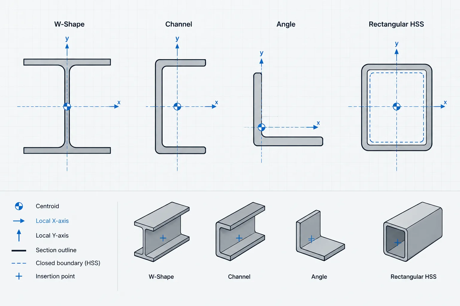
Published centroid coordinates should be interpreted from the reference axes used by the source. Before placing a section by centroid, verify:
- which leg is horizontal and which is vertical;
- whether the long leg or short leg is associated with each coordinate;
- where the coordinate origin is located;
- whether the block has been mirrored or rotated; and
- whether the model line represents a centroid, a back, or another cardinal point.
The angle’s principal axes are also rotated relative to axes parallel to the legs. That distinction is important in analysis and section-property work, but fabrication dimensions are usually clearer when tied to physical backs, edges, or connection work lines.
Connected leg and outstanding leg terminology
In a connection, the connected leg is the leg attached to another component. The outstanding leg projects away from the connection plane. These descriptions communicate function, while long-leg vertical, short-leg outstanding, or similar orientation notes communicate geometry.
Neither description should be inferred solely from the angle designation. The same unequal-leg angle can be installed in multiple orientations. A model or drawing should make the orientation explicit enough that the fabricator does not need to guess which leg receives holes or welds.
For paired angles, also clarify whether the backs, toes, or outstanding legs face each other. A section view is often more reliable than a text note alone.
Choosing simplified or detailed CAD geometry
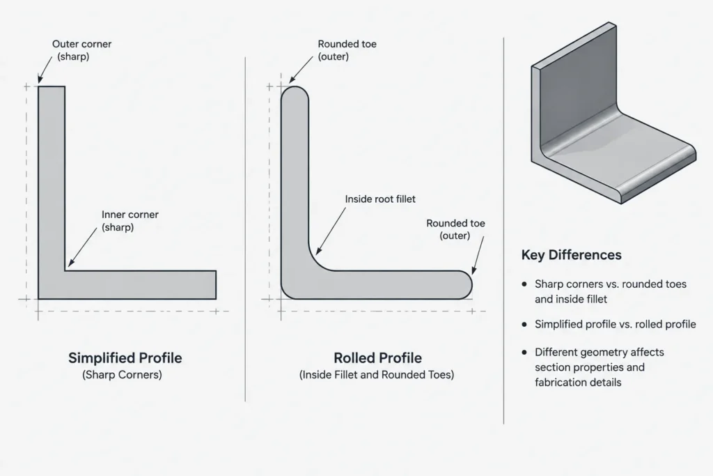
A simplified angle can be drawn with straight leg faces, uniform nominal thickness, a sharp theoretical heel, and square toes. This is often sufficient for framing plans, member diagrams, early coordination, and small-scale details.
A detailed profile may include the root fillet, toe radii, and a carefully located centroid. Use that level of geometry when it serves a defined purpose, such as:
- checking whether a plate clears the root fillet;
- developing a close-fitting profile or notch;
- comparing calculated section properties with tabulated values;
- preparing an enlarged connection section; or
- reviewing interference with bolt heads, washers, welds, or adjacent parts.
Do not mix levels of accuracy unintentionally. Adding an approximate fillet to an otherwise simplified profile can make the block look authoritative without making it dimensionally reliable. If exact geometry is required, build or verify the profile using an appropriate published shape reference.
A practical angle-detailing workflow
- Confirm the designation. Distinguish equal-leg from unequal-leg angles and verify the intended leg orientation.
- Select the controlling datum. Use a back of leg, work line, supporting face, or another clearly defined physical reference.
- Place the section consistently. Check the CAD insertion point and rotation before copying or mirroring it.
- Lay out connection geometry from stated references. Do not assume a bolt gage is measured from the centroid or toe.
- Check the heel region. Review root-fillet clearance wherever another part approaches the inside corner.
- Check the toes. Confirm edge relationships and overall clearance using the appropriate profile accuracy.
- Coordinate views and marks. Make sure plans, elevations, sections, bills of material, and CNC information describe the same orientation.
- Verify critical geometry. Compare the final detail with the governing project information and trusted shape data.
Common angle-geometry mistakes
- Using the bounding-box center as though it were the section centroid.
- Dimensioning to an implied sharp inside corner that does not physically exist.
- Failing to distinguish the long-leg toe from the short-leg toe.
- Mirroring an unequal-leg angle without updating orientation notes or hole locations.
- Assuming a generic CAD angle includes accurate rolled radii.
- Placing a fitted plate into the root-fillet zone.
- Using heel, back, and centroid as interchangeable reference terms.
Use geometry according to its purpose
Angle detailing becomes clearer when placement geometry, physical material boundaries, and analytical reference points are treated separately. The backs are useful fabrication datums, the theoretical heel is a convenient construction point, the root radius controls inside-corner fit, the toes define the free leg ends, and the centroid supports section-property and member-axis work.
A dependable drawing does not need to show every rolled contour in every view. It does need to identify orientation, use consistent datums, and represent critical clearance zones accurately enough for the task. When a connection depends on the actual profile, verify the selected angle against appropriate shape data rather than relying on a nominal sketch.