A row of bolt holes reduces the effective cross section of a steel tension element. When the holes line up across the member, identifying the likely net section is relatively direct. When adjacent bolt lines are staggered, however, a possible failure path can run diagonally from one hole to another. That geometry changes how the remaining section is evaluated and makes drawing clarity especially important.
This guide explains the terminology, path logic, and CAD workflow used to study staggered bolt holes in plates and connected legs of angles. It is intended as a practical reference rather than a substitute for connection design calculations. Hole deductions, effective net area, block shear, shear lag, and connection strength must be checked under the governing project criteria.
What is a net-section path?
The gross section is the complete cross section before holes or other material removals are considered. A net section is the remaining material along a potential rupture path after applicable hole deductions are made.
For a tension plate with holes arranged in transverse rows, a straight path may cross several holes at the same longitudinal location. If the holes are staggered, other candidate paths can zigzag diagonally between bolt lines. The critical path is not automatically the shortest-looking line or the path crossing the most holes. It is the path that produces the governing net area after all applicable deductions and stagger adjustments are evaluated.
A connection can have several plausible paths:
- A straight transverse path through one or more aligned holes.
- A diagonal path between staggered holes on adjacent bolt lines.
- A mixed path containing both transverse and diagonal segments.
- A path through only part of a connected element, depending on its geometry and load transfer.
Each credible path should be identified systematically rather than selected by visual judgment alone.
Pitch, gage, and hole deduction terminology
Stagger calculations depend on dimensions measured in different directions relative to the applied force. Keeping these directions clear prevents one of the most common calculation errors.

| Term | Practical meaning | Direction |
|---|---|---|
| Pitch | Spacing between holes along a bolt line | Generally parallel to the member force or longitudinal axis |
| Gage | Spacing between adjacent bolt lines | Generally transverse to the member force |
| Stagger | Longitudinal offset between holes on adjacent bolt lines | Parallel to the member force |
| Hole deduction | Width removed from the section for a crossed hole | Applied across the net-section path |
| Edge distance | Distance from a hole center to a material edge | Depends on the referenced edge and load direction |
On connection drawings, pitch and stagger can appear similar because both are longitudinal measurements. Pitch usually describes spacing within the same bolt line. Stagger describes the offset between holes in different bolt lines. A clear plan or elevation should show which hole centers each dimension controls.
How the diagonal stagger adjustment works
A diagonal path crosses more material than a direct transverse path between the same bolt lines. Net-width calculations commonly represent this additional material with a stagger term based on the longitudinal offset and transverse spacing.
For a constant-thickness flat element, a commonly used geometric expression for a candidate path is:
Net width = gross width − hole deductions + stagger adjustments
For an individual diagonal segment, the geometric stagger adjustment is commonly expressed symbolically as s²/(4g), where s is the longitudinal stagger between the relevant hole centers and g is the transverse spacing between their bolt lines. If a path contains more than one diagonal segment, each applicable segment is considered separately.
This adjustment does not mean that a hole adds material. Every crossed hole still creates a deduction. The positive stagger term accounts for the longer diagonal strip of material between holes.
The net area of a flat element with uniform thickness can then be related to its net width by multiplying by the thickness. More complicated sections may require separate treatment of individual elements, connected legs, outstanding legs, or changes in thickness.
A repeatable path-evaluation workflow
1. Establish the force direction
Mark the assumed direction of tension on the sketch. This determines which dimensions are longitudinal and which are transverse. Do not rely only on the sheet orientation; a member can be sloped, rotated, or shown in an auxiliary view.
2. Identify the gross section under consideration
Define the complete width or developed width used for the candidate section. For a plate, this is usually straightforward. For an angle or another nonplanar shape, confirm how the connected elements are being treated and whether a developed representation is needed.
3. Draw every credible path
Begin at one free edge and trace paths to the opposite free edge. Include straight paths, single-diagonal paths, and zigzag paths where the hole arrangement permits them. Label the paths so calculations and drawing markups can be compared without ambiguity.
4. Count crossed holes
For each path, record every hole it intersects. Use the required calculation hole deduction rather than assuming that the nominal bolt diameter, modeled opening, or drawing symbol is the correct deduction. Slotted and oversized holes require particular care because orientation can affect the applicable transverse deduction.
5. Record each diagonal pair
For every diagonal segment, identify the corresponding stagger s and gage g. A long zigzag path can involve different values at different locations. Do not apply one typical spacing to the entire path unless the geometry actually repeats.
6. Compare the resulting net sections
Evaluate all candidate paths using a consistent sign convention and units. The path with the least calculated net area is a critical candidate for net-section rupture, but it is not necessarily the only connection limit state that must be checked.
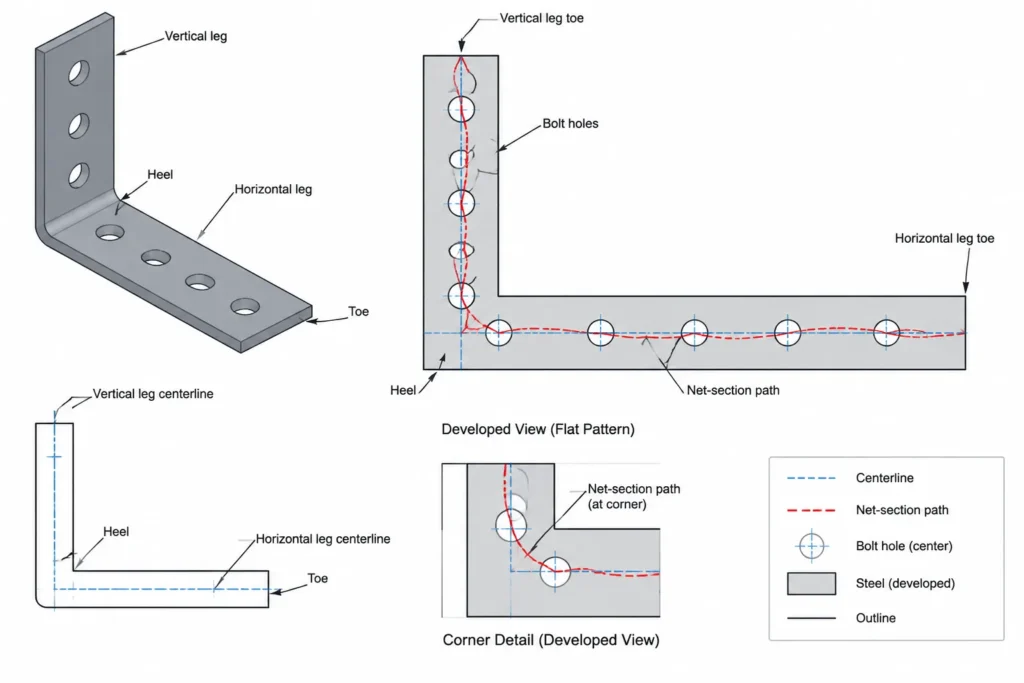
Applying the concept to steel angles
Angles introduce an extra geometric issue because their legs meet at a heel rather than lying in one flat plane. A bolt pattern may occupy one leg, both legs, or a connected leg with an outstanding leg that participates differently in the tension response.
When a path crosses from one angle leg to the other, the spacing should be based on the applicable developed geometry rather than a misleading projected distance from a single drawing view. The heel region, leg thickness, rolled fillet, and chosen reference lines can affect how dimensions are interpreted.
For drafting and checking:
- Identify whether dimensions are measured from the heel, toe, back of angle, or bolt-line center.
- Keep bolt-line gages tied to explicit references.
- Use a developed sketch when a path crosses both legs.
- Do not model the angle as a sharp-cornered plate fold and assume that every measured CAD distance represents the design dimension.
- Distinguish the geometric net area from any effective net-area treatment associated with incomplete load transfer or shear lag.
Net-section rupture is not block shear
A zigzag net-section path should not be confused with a block shear path. A net-section rupture path generally crosses the member transverse to the force, with possible diagonal transitions between holes. A block shear pattern surrounds a block of material using a combination of longitudinal shear planes and a transverse tension plane.
The same bolt group can contain plausible paths for both checks. Finding a generous staggered net section does not establish that the surrounding edge distances, end distances, shear planes, bearing behavior, or block shear resistance are adequate.
CAD methods that improve checking
CAD is useful for organizing the geometry, but an automatically measured polyline length is not a substitute for the net-width expression. The calculation is based on prescribed deductions and geometric terms, not simply the physical length of a drawn fracture line.
- Use hole-center points: Create dependable center marks or point objects for each hole.
- Separate reference directions: Establish construction lines parallel and perpendicular to the force direction.
- Dimension center to center: Extract stagger and gage from hole centers, not from circle quadrants.
- Overlay candidate paths: Put each path on a temporary checking layer with a unique label.
- Check transformed views: If the connection is skewed or sloped, measure in the true plane of the connected element.
- Preserve hole metadata: Distinguish round holes from slots and record slot orientation instead of representing every opening with the same generic circle.
A spreadsheet or calculation note can list each path, number of crossed holes, diagonal segments, and resulting net width. Matching those path labels to the CAD overlay makes independent review much easier.
Common errors in staggered-hole layouts
- Checking only the visually obvious straight path.
- Using pitch where transverse gage is required, or reversing the two variables.
- Subtracting nominal bolt diameter without confirming the required hole deduction.
- Adding a stagger term without also deducting the holes crossed by that path.
- Using projected spacing from an oblique view instead of true in-plane spacing.
- Treating a polyline length as the net width.
- Ignoring a path that crosses fewer holes but has less favorable stagger geometry.
- Assuming the net-section check also covers block shear, bearing, tear-out, or connection eccentricity.
- Forgetting that angle geometry may need to be developed across the heel.
Practical review checklist
- Is the force direction clearly marked?
- Are pitch, gage, and stagger measured in the correct directions?
- Have straight, diagonal, and mixed paths been considered?
- Does every path use the appropriate hole deduction?
- Are all diagonal segments paired with their actual center-to-center dimensions?
- For angles, is the path based on suitable developed geometry?
- Are net-section and block shear checks kept distinct?
- Do the calculation sketch and fabrication drawing show the same hole layout?
- Have slots, edge conditions, and connection-specific load-transfer effects been identified for engineering review?
Staggered bolt patterns can improve connection layout and fit, but they make the potential rupture geometry less obvious. A disciplined process—establishing the force direction, labeling candidate paths, measuring true center-to-center spacing, and separating net-section behavior from other limit states—turns a complicated-looking pattern into a traceable design and detailing check.