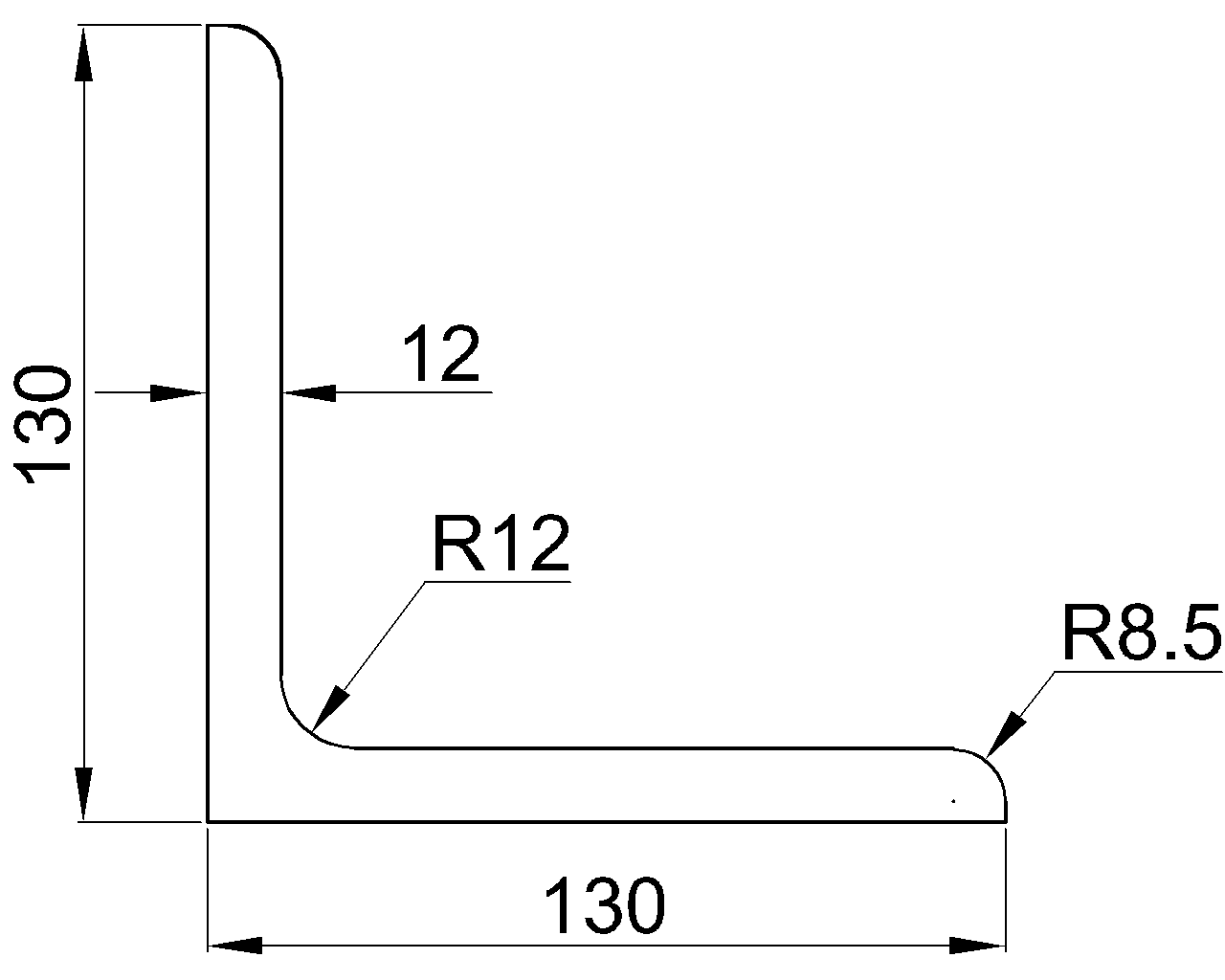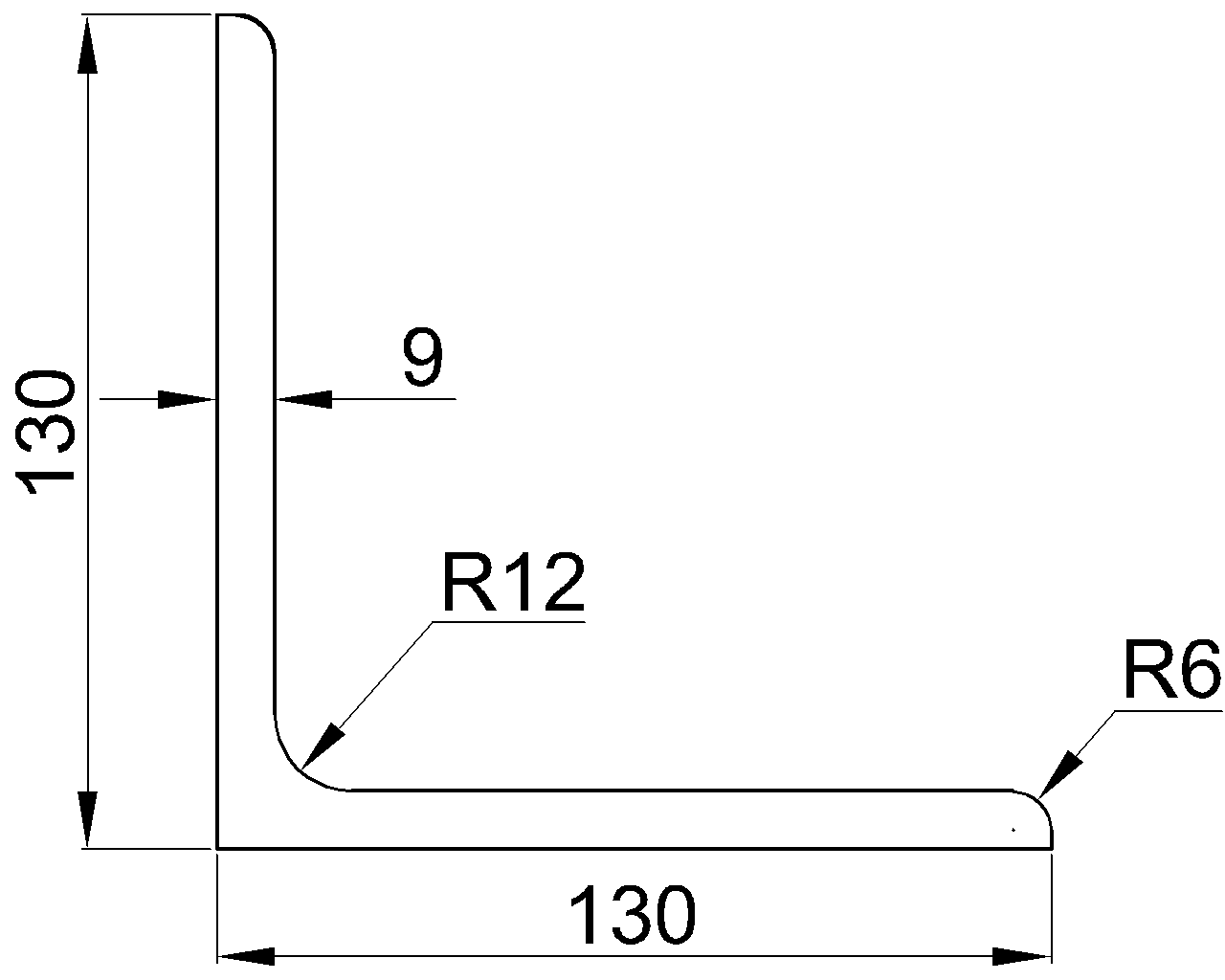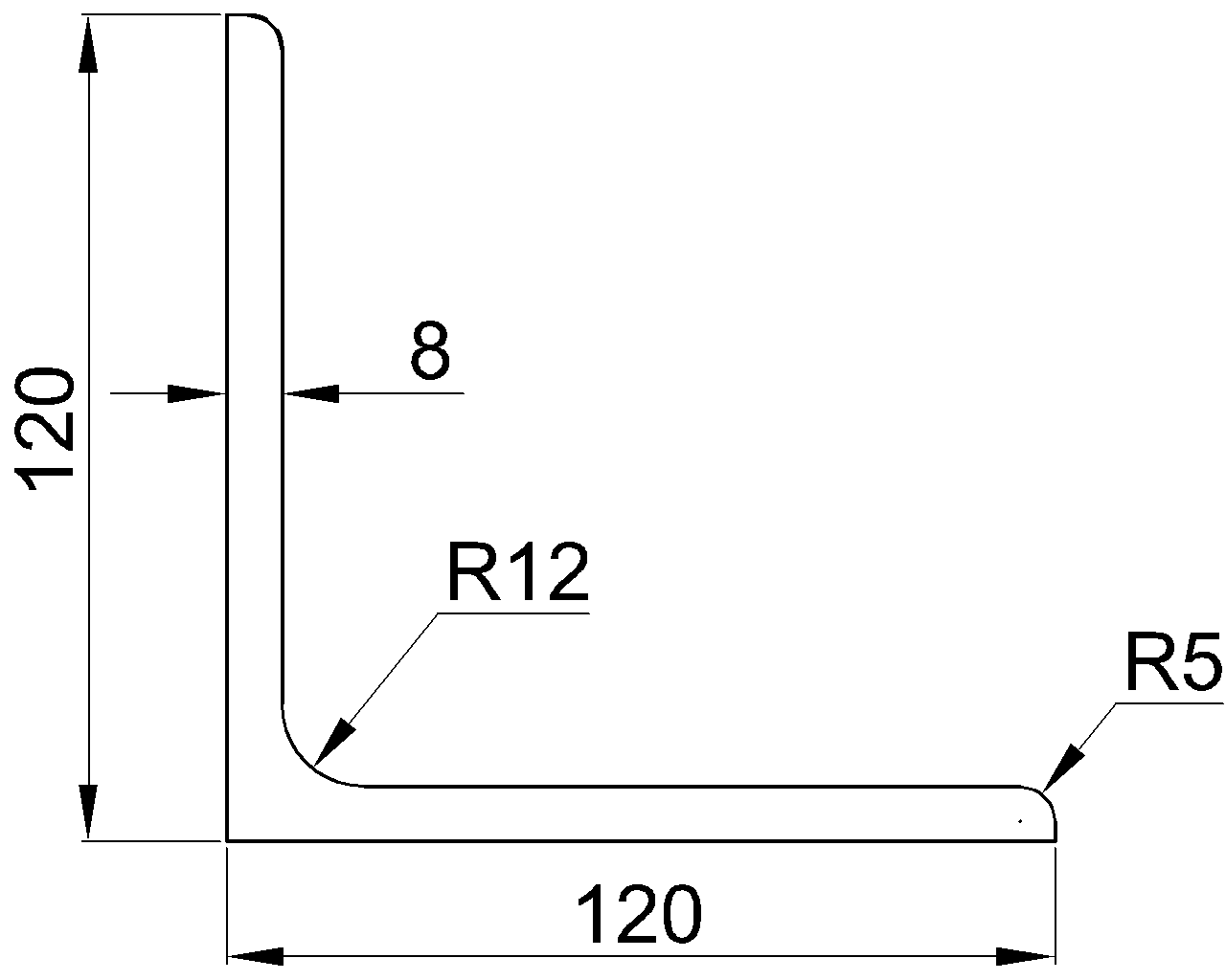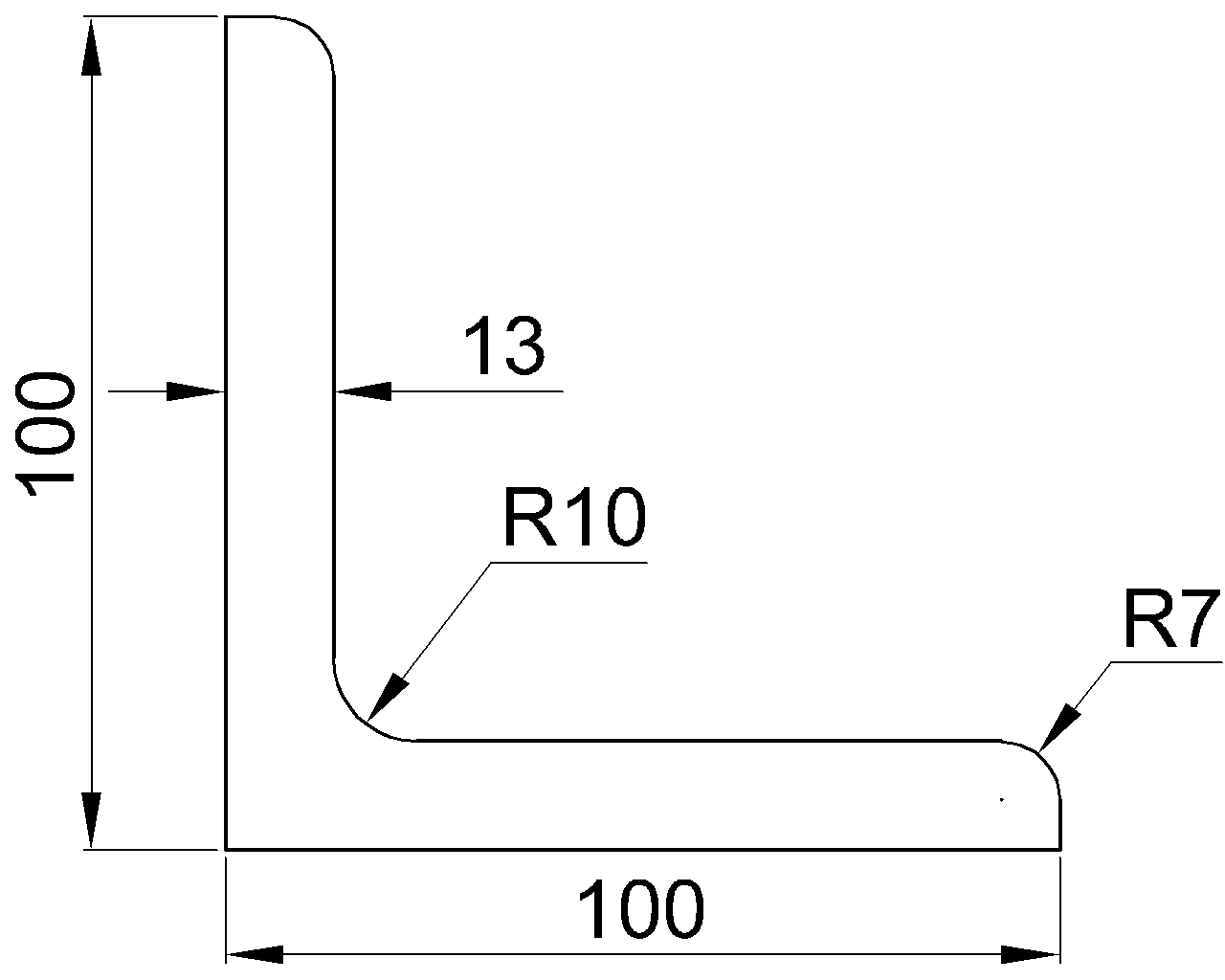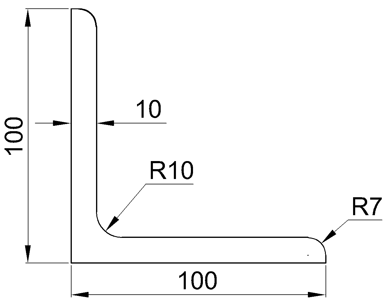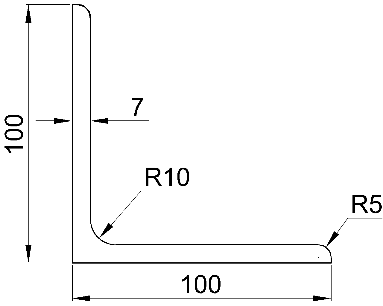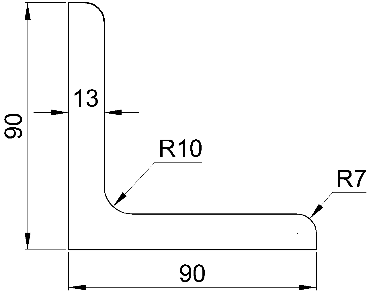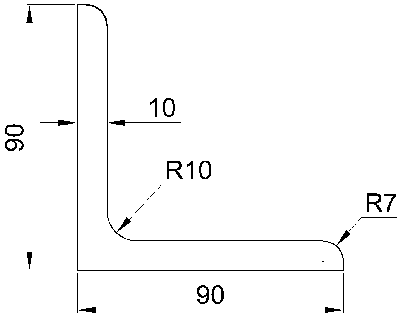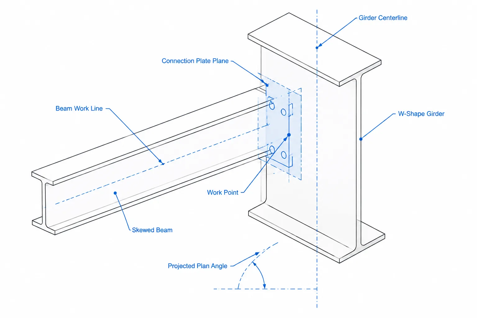
Skewed structural steel connections occur when members meet at an angle other than a conventional perpendicular intersection in plan. They are common at curved building edges, angled grids, ramps, bridges, canopies, transfer framing, and architectural features. Although the framing may look straightforward in plan, the connection geometry can become difficult to communicate when skew, slope, member rotation, and eccentricity occur together.
The central detailing problem is that a plan angle does not fully define a three-dimensional connection. A reliable model or shop drawing must distinguish the member work line, the actual steel faces, the connection plane, and the dimensions controlling fabrication. Keeping those references separate helps prevent incorrect plate lengths, distorted hole spacing, unexpected weld gaps, and reversed assemblies.
What Makes a Connection Skewed?
A connection is skewed when the supported member approaches the supporting member at an oblique angle in plan. For example, a beam work line may intersect a girder work line without being perpendicular to it. The plan view shows the horizontal relationship, but it does not necessarily show the true shape of the end connection.
Several independent geometric conditions may be present:
- Plan skew: The member work lines intersect obliquely when viewed from above.
- Member slope: A member rises or falls between its ends.
- Section rotation: The cross-section is rotated about the member’s longitudinal axis.
- Supporting-face orientation: The connection attaches to a flange, web, HSS wall, plate, or other face that has its own plane.
- Offset framing: The member work lines do not intersect at the physical connection center.
These conditions should not be combined into a single vaguely labeled angle. Each describes a different relationship and may affect different fabricated parts.
Start with Work Lines and Work Points
The member work line is the most stable reference for laying out skewed framing. It normally represents a defined longitudinal axis, such as a beam centerline or another project-specific reference. A work point identifies a controlling intersection, grid location, or theoretical framing point.
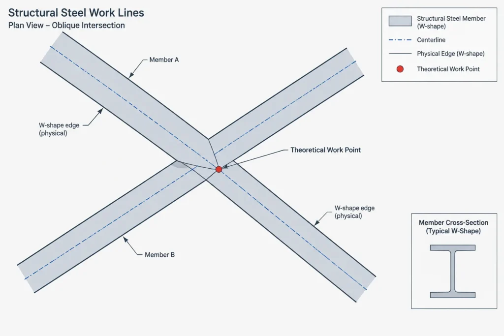
In a clean CAD workflow, establish the supporting-member work line and incoming-member work line before drawing connection plates or cutting member ends. The angle between those lines in plan defines the framing skew. Physical steel geometry can then be developed from the work lines using verified section dimensions and documented offsets.
This order matters because faces of steel may not pass through the work point. A W-shape flange face is offset from its member centerline, an HSS wall is offset from the HSS centerline, and a connection plate may be intentionally eccentric. Extending visible edges until they cross can therefore create a false layout point.
Plan Angle Is Not Always the True Angle
For horizontal members with no section rotation, the plan relationship may be enough to establish much of the connection geometry. Once a member slopes, however, the angle shown in plan is only a projection. The actual spatial angle between the members is different from that projected angle.
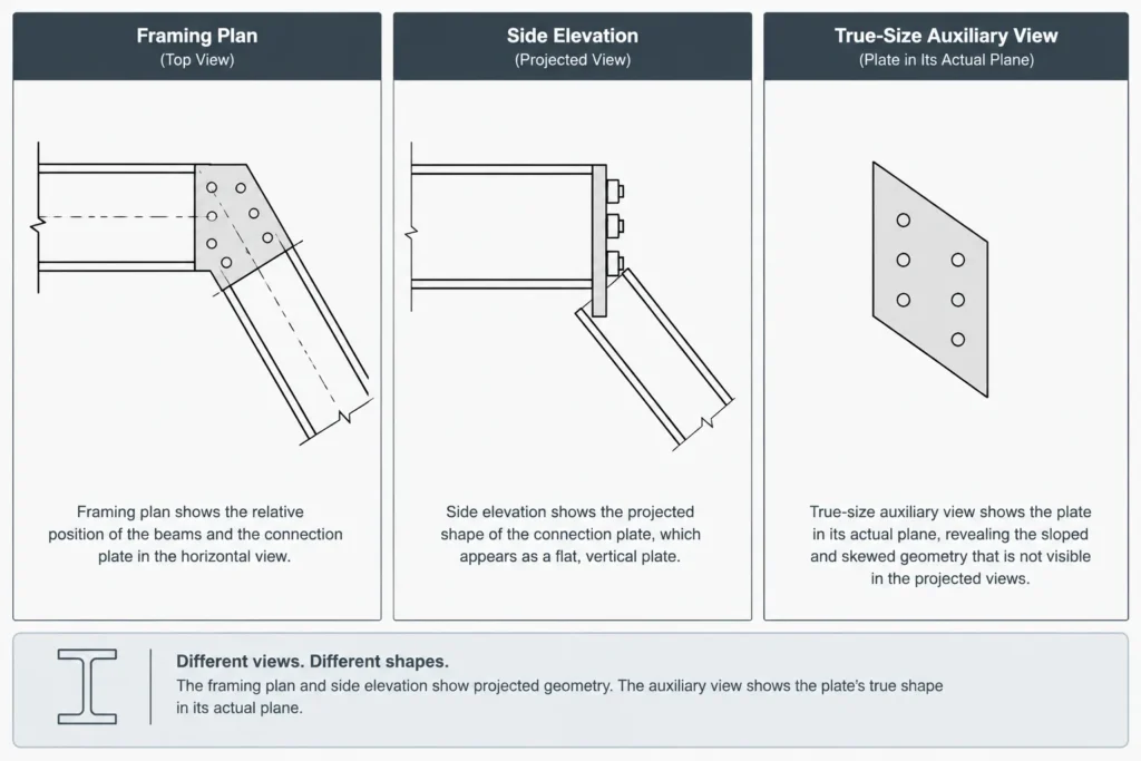
This distinction affects end cuts, end plates, shear plates, stiffeners, and other components whose fabrication depends on the true plane of intersection. A dimension taken from an ordinary plan or elevation may be shortened by projection. CAD geometry should be examined in a view normal to the relevant connection plane when true dimensions are needed.
Three Useful Views
- Framing plan: Best for work lines, grid relationships, plan skew, handedness, and erection orientation.
- Elevation or member view: Best for slope, vertical offsets, top-of-steel relationships, and connection height.
- True-size connection view: Best for plate outlines, hole patterns, edge distances, weld extents, and cuts measured in the component’s own plane.
No single view should be expected to communicate every geometric condition. When a plate appears foreshortened in the main elevation, a true-size auxiliary view can define it without relying on interpretation.
Choose and Document the Connection Plane
The connection plane is the plane in which a plate, bolt group, weld interface, or cut is actually located. On a skewed beam connection, that plane might be parallel to the supporting web, normal to the incoming beam work line, aligned with an end plate, or set to another engineered orientation.
Those alternatives are not geometrically interchangeable. A plate parallel to a girder web has a different relationship to the incoming beam than a plate square to the incoming beam. The choice affects plate shape, bolt fit, weld access, and the gap between connected parts.
A detail should make the intended plane visually and dimensionally clear. Useful methods include a section normal to the plate, a labeled viewing direction, centerlines through the bolt group, or dimensions referenced to a defined face. Avoid expecting a generic connection symbol to resolve an unusual skew automatically.
Skew Geometry and Common Connection Parts
| Connection part | Geometry to confirm | Typical detailing concern |
|---|---|---|
| Shear plate | Plate plane, beam web relationship, and bolt-line location | Clearance between the beam flange and supporting member |
| End plate | Plate orientation relative to the member and supporting face | True plate outline, bolt access, and weld fit-up |
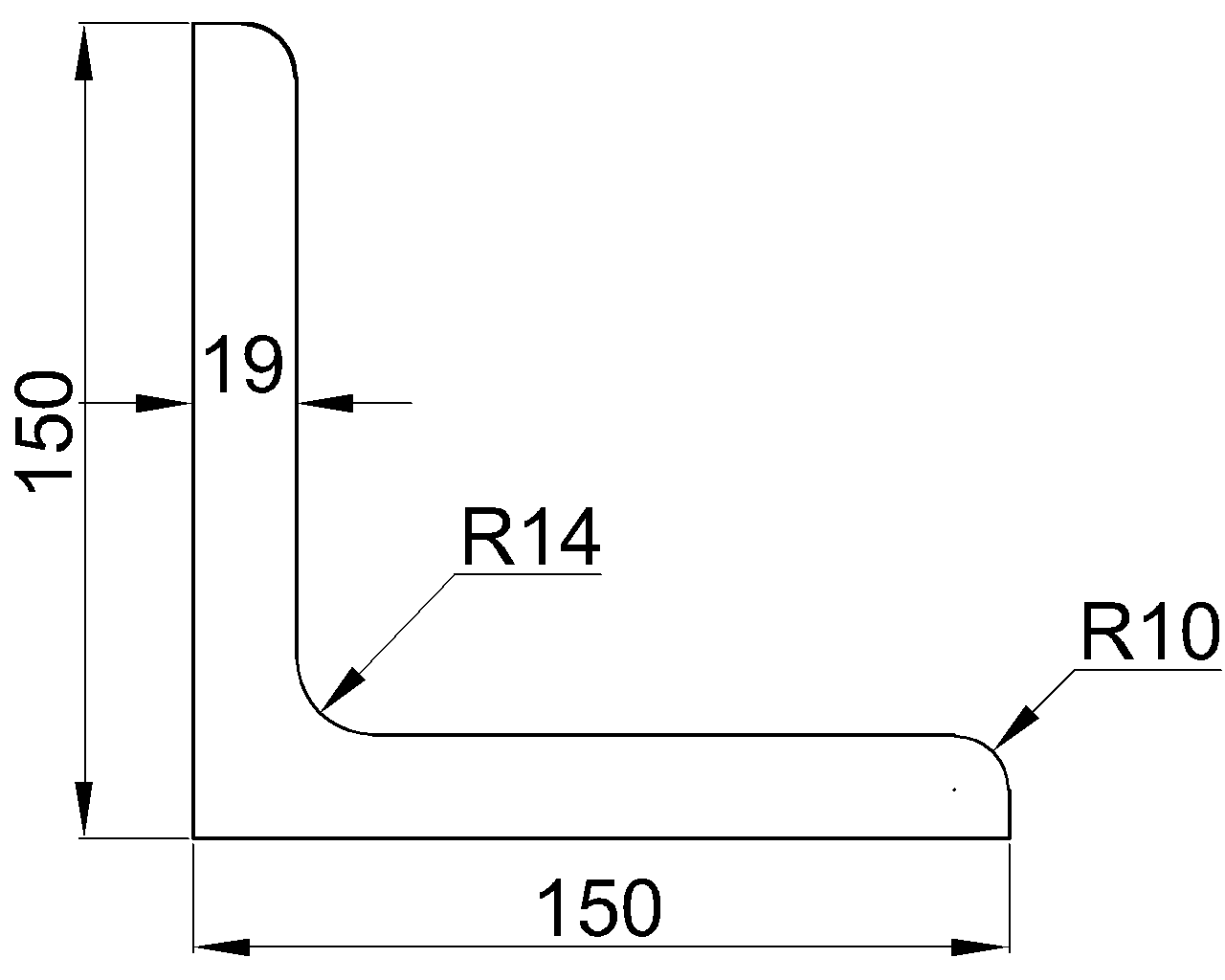
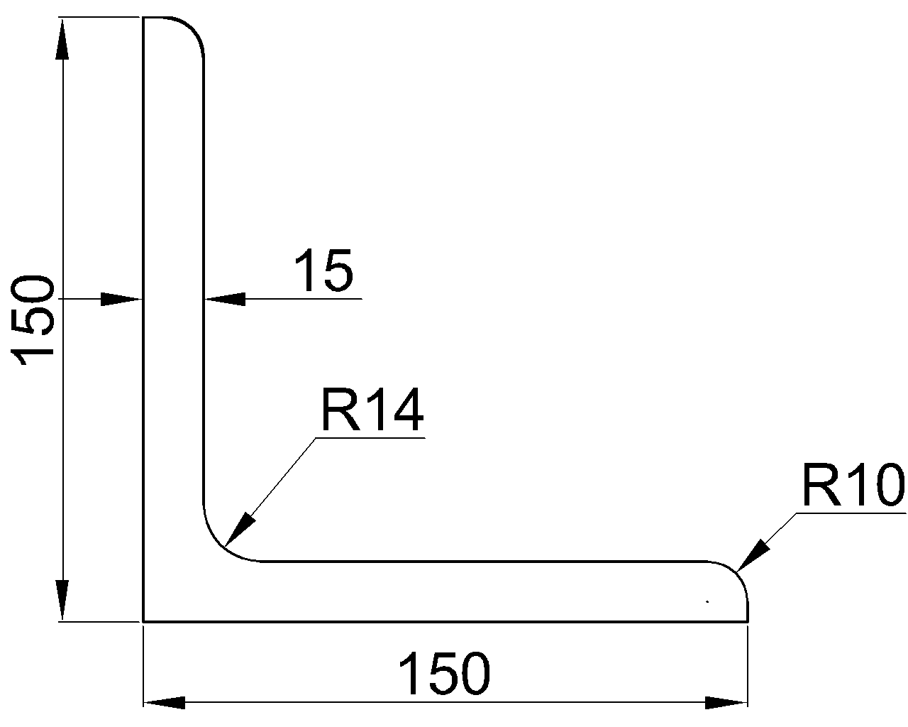
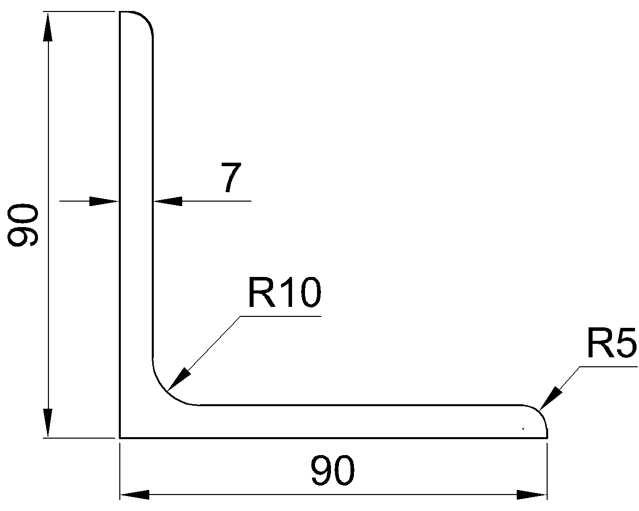
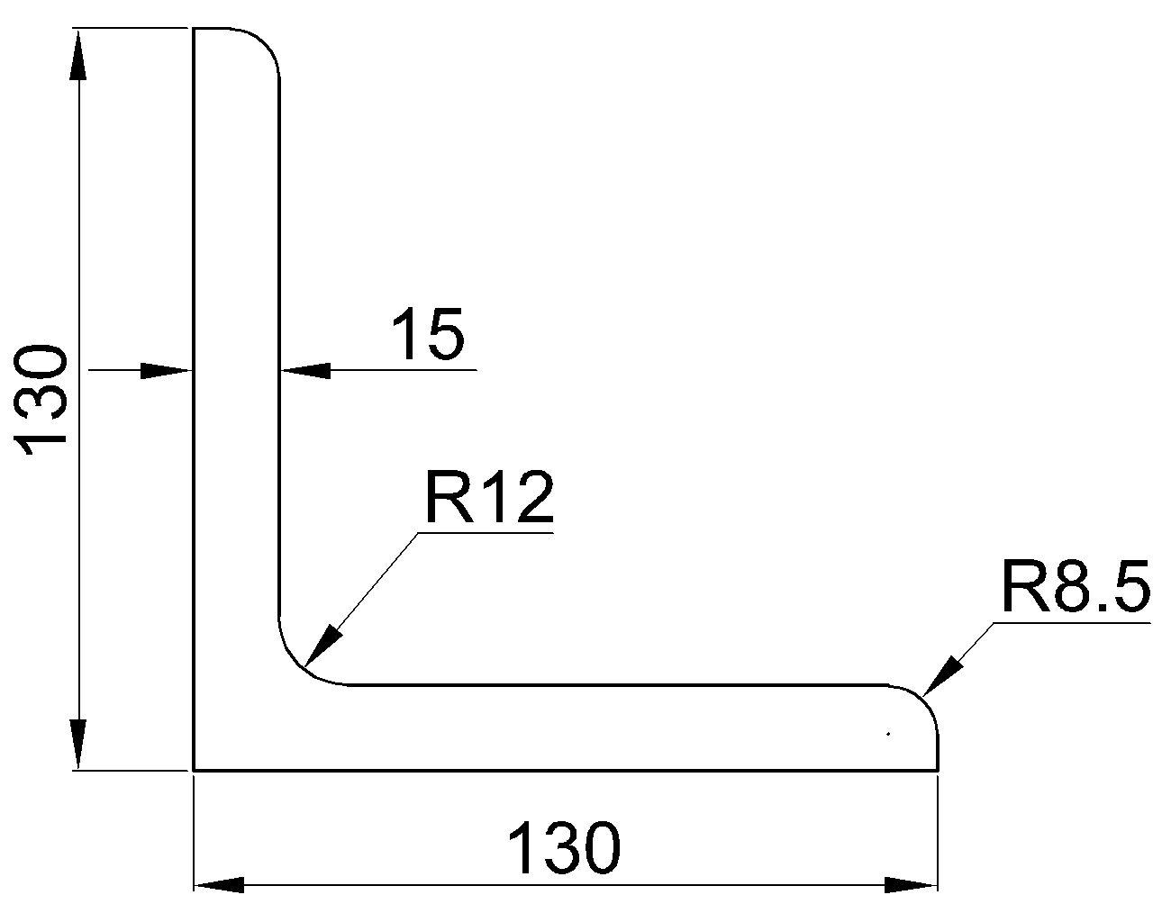
| Clip angles | Connected-leg planes and angle orientation | Unequal gaps, handed parts, and access to bolts |
| Seat or bearing plate | Actual bearing plane and supported-member footprint | Partial contact caused by slope or skew |
| Gusset plate | Brace work line, plate plane, and intersection region | Eccentricity and true edge geometry |
| HSS end connection | HSS face, member axis, and end-cut plane | Compound cuts and nonuniform weld gaps |
Setbacks, End Cuts, and Physical Clearance
A setback is meaningful only when its reference and measurement direction are defined. On orthogonal framing, a setback measured along the member work line may appear to match a face-to-end distance. Under skewed conditions, those values can differ substantially.
Identify whether a dimension controls:
- distance along the incoming member work line;
- perpendicular distance from a supporting face;
- distance to a theoretical work point;
- minimum physical clearance between steel surfaces; or
- the location of a cut plane.
Skewed member ends also require attention at both edges of the section. A cut that clears the supporting face at one flange tip may interfere at the opposite tip. Similar problems can occur at HSS corners, channel toes, angle legs, and rolled-shape fillets. Checking only a centerline section can hide these edge conditions.
Hole Patterns and Dimensioning
Hole spacing should normally be defined in the plane of the material containing the holes. If a plate is skewed relative to the drawing view, dimensions copied from its projected appearance may not represent true fabrication distances.
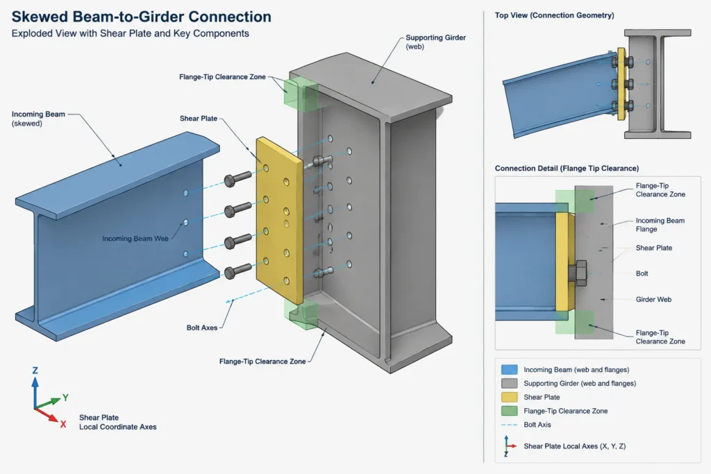
For a clear hole layout, establish a plate-local coordinate system or dimension from identifiable plate edges and centerlines. Keep the following distinctions visible:
- hole coordinates in the plate plane;
- the bolt-group center relative to the connection work point;
- the plate location relative to the supporting member; and
- the incoming member location relative to the bolt group.
When matching holes occur in parts lying in different planes, a three-dimensional model check is especially valuable. Apparent alignment in one projected view does not prove that the bolt axes are coincident.
Handedness and Mirrored Connections
Skewed connections are frequently handed. A connection at one end of a symmetric framing bay may look like a mirror image of the connection at the other end, but fabrication features do not always mirror cleanly. Member slopes, near-side plates, weld access, erection sequence, and section asymmetry can make the two assemblies different.
Do not create an opposite-hand detail by mirroring geometry without reviewing text, dimensions, hole references, section marks, and weld locations. Assigning distinct piece or assembly marks is often appropriate when the physical parts are not interchangeable.
A Practical CAD Checking Workflow
- Build the framing skeleton. Lay out grids, work points, member work lines, slopes, and offsets independently of connection solids.
- Place verified section geometry. Confirm section orientation, insertion point, and local axes.
- Define the supporting face. Identify the actual flange, web, HSS wall, plate, or other surface receiving the connection.
- Define the connection plane. Do not infer it solely from the plan skew.
- Develop parts in their true planes. Create plates and hole patterns using local geometry rather than projected dimensions.
- Check extreme edges. Review flange tips, toes, corners, fillets, weld zones, bolt heads, nuts, and tool access.
- Review the model from multiple directions. Use plan, elevation, section, and a view normal to the connection plane.
- Extract fabrication dimensions deliberately. Confirm whether each dimension is true length, projected length, perpendicular clearance, or distance along a work line.
- Check handedness. Compare similar connections rather than assuming they are interchangeable.
- Coordinate design intent. Unusual geometry, eccentricity, connection orientation, and load-path questions require review by the responsible project team.
What the Final Detail Should Communicate
A successful skewed connection detail does more than show that two members meet at an angle. It identifies the references needed to reproduce the geometry: member work lines, work point, plan orientation, elevation or slope, supporting face, connection plane, true part shape, and controlling dimensions.
CAD models and shape blocks are useful geometric tools, but they do not determine whether a connection arrangement is structurally appropriate, fabricable, or acceptable for a specific project. Final geometry must be coordinated with the project drawings, connection design, fabrication requirements, erection needs, and verified steel-shape data.