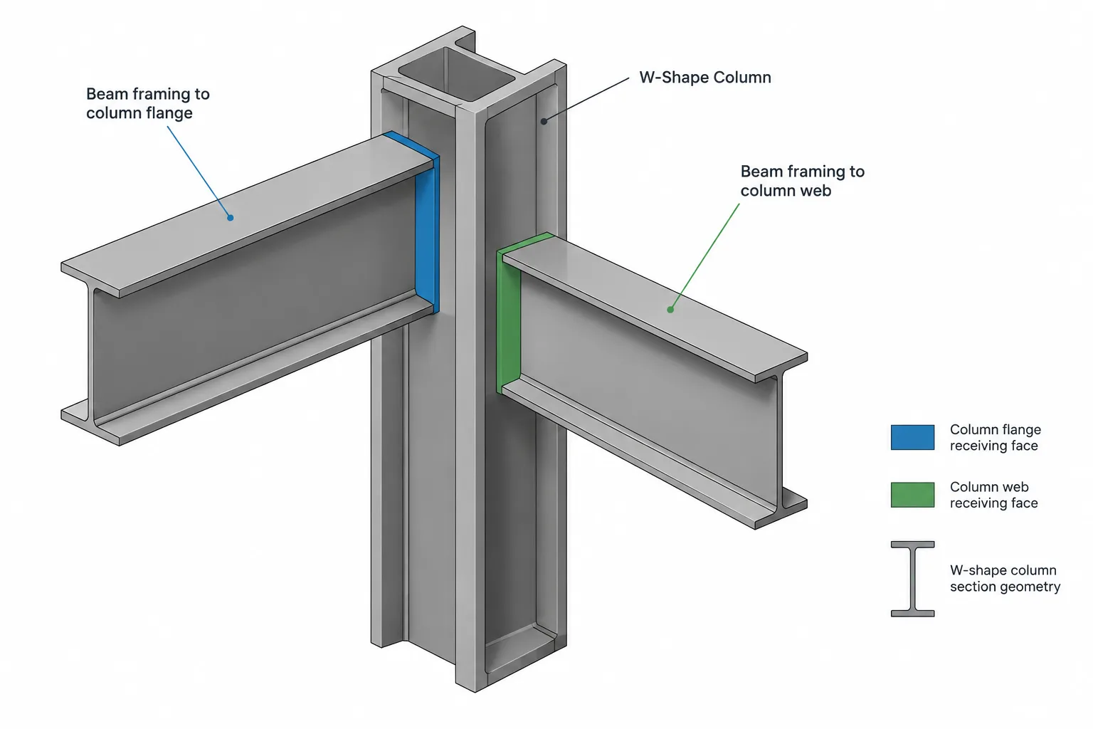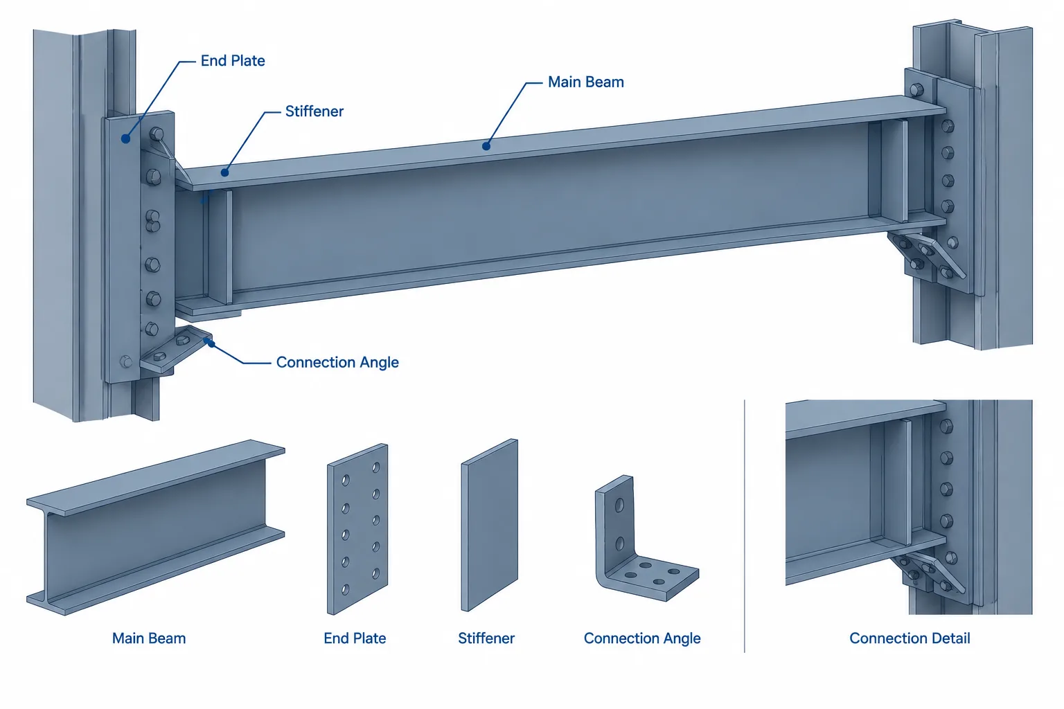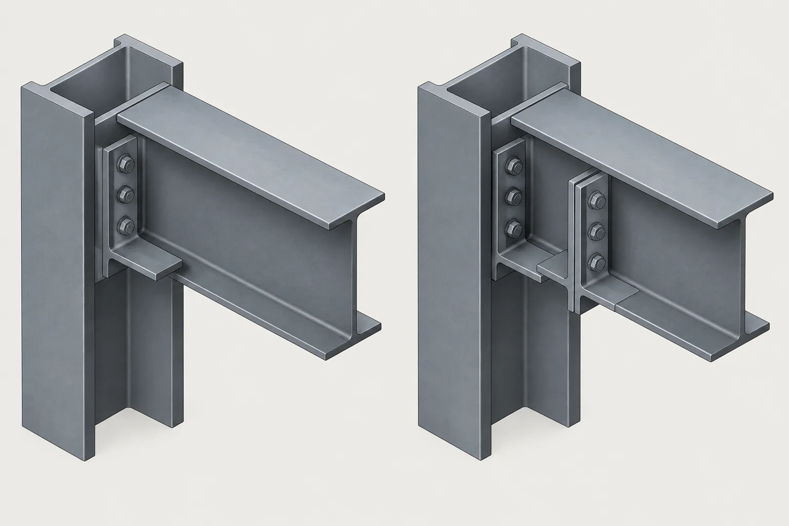
Framing angles are commonly used to connect the web of a steel beam to a supporting beam, column, or other structural element. Depending on the connection design, the beam may have an angle on only one side of its web or matching angles on both sides. These arrangements are often described as single-angle and double-angle shear connections.
The difference is more significant than the number of angles. Angle placement affects connection eccentricity, bolt access, shop attachment, erection sequence, beam-end preparation, drawing clarity, and the geometry that must be represented in CAD. The connection configuration must come from the project design documents or an authorized connection design; it should not be selected merely because one arrangement is easier to draw or fabricate.
Basic connection arrangements
Single-angle connection
A single-angle connection places one framing angle against one face of the supported beam web. One leg of the angle connects to the beam web, while the other leg connects to the supporting element. Depending on the specified connection, either interface may be bolted or welded.
Because the angle is located on only one side of the web, its position should be identified unambiguously. A plan, section, or end view may be needed to establish whether it is on the near side or far side of the beam web. An elevation alone can hide this important orientation.
Double-angle connection
A double-angle connection places an angle on each side of the supported beam web. The angles commonly form a paired arrangement, but a detailer should not assume that every feature is automatically symmetrical. The supporting member geometry, erection requirements, bolt direction, weld arrangement, or adjacent obstructions may create differences between the two sides.
In CAD, each angle should remain identifiable even when the pair is modeled or drafted as a repeated component. Treating the entire connection as an undifferentiated symbol can conceal side-specific holes, welds, cuts, or clearances.
Key differences for detailing
| Detailing issue | Single-angle connection | Double-angle connection |
|---|---|---|
| Position relative to beam web | Located on one face, so near-side or far-side orientation is critical | Located on both faces, often appearing balanced in section |
| Connection eccentricity | The one-sided arrangement may introduce geometric eccentricity that must be addressed by the connection design | The paired arrangement may provide more balanced geometry, but design behavior must not be assumed from appearance |
| Beam-web access | One face of the web remains unobstructed by a framing angle | Both faces are occupied locally by the angle pair |
| Bolt installation | Tool access depends strongly on the selected side and nearby steel | Access must be checked on both sides and between adjacent components |
| Drawing requirements | Usually needs a clear side-location note or view | Needs confirmation of symmetry, bolt direction, and separate side conditions |
| CAD component handling | A mirrored insertion can accidentally place the angle on the wrong side | Copying or mirroring can conceal intentional differences between angles |
Connected leg and outstanding leg
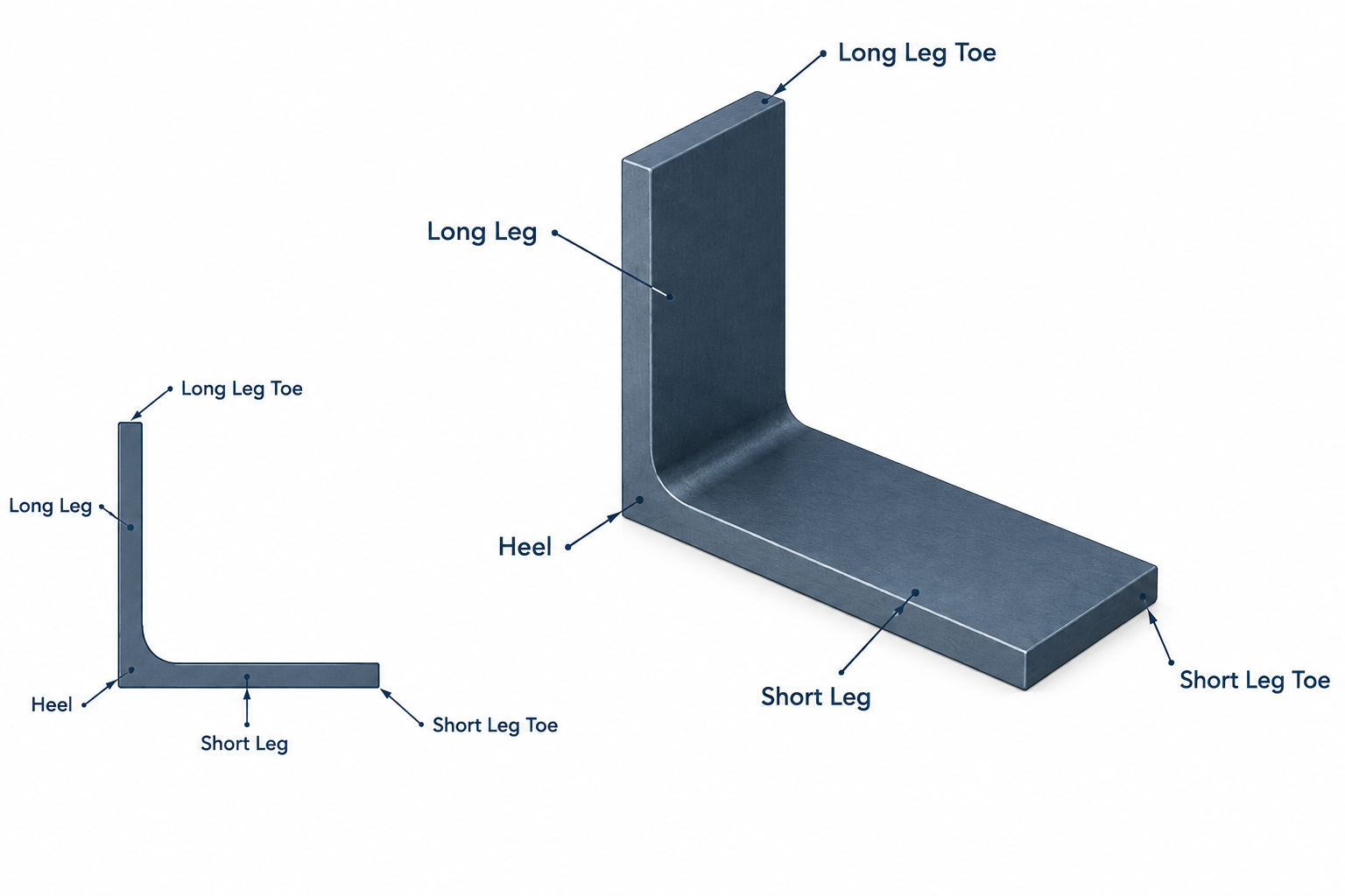
An angle has two legs meeting at the heel. In connection discussions, the leg attached to a particular member may be called the connected leg. The other leg is often called the outstanding leg relative to that interface. The terminology depends on which connection surface is being discussed, so it is better to describe the relationship explicitly than to rely on the word “outstanding” by itself.
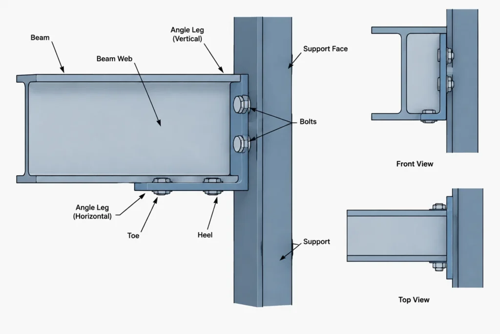
For a typical beam-web framing angle, one leg lies against the supported beam web and the other lies against the support. The angle toes, heel, and rolled fillet must be oriented correctly. Reversing the angle can change:
- The location of bolt lines relative to the angle heel and toe
- Clearance between bolt heads, nuts, and the rolled fillet
- The position of welds and accessible weld faces
- The fit between the beam end and supporting member
- The overall projection of the connection
An angle designation alone does not fully define this orientation. The drawing should show which leg contacts each member, especially when an unequal-leg angle is used.
Shop attachment and field attachment
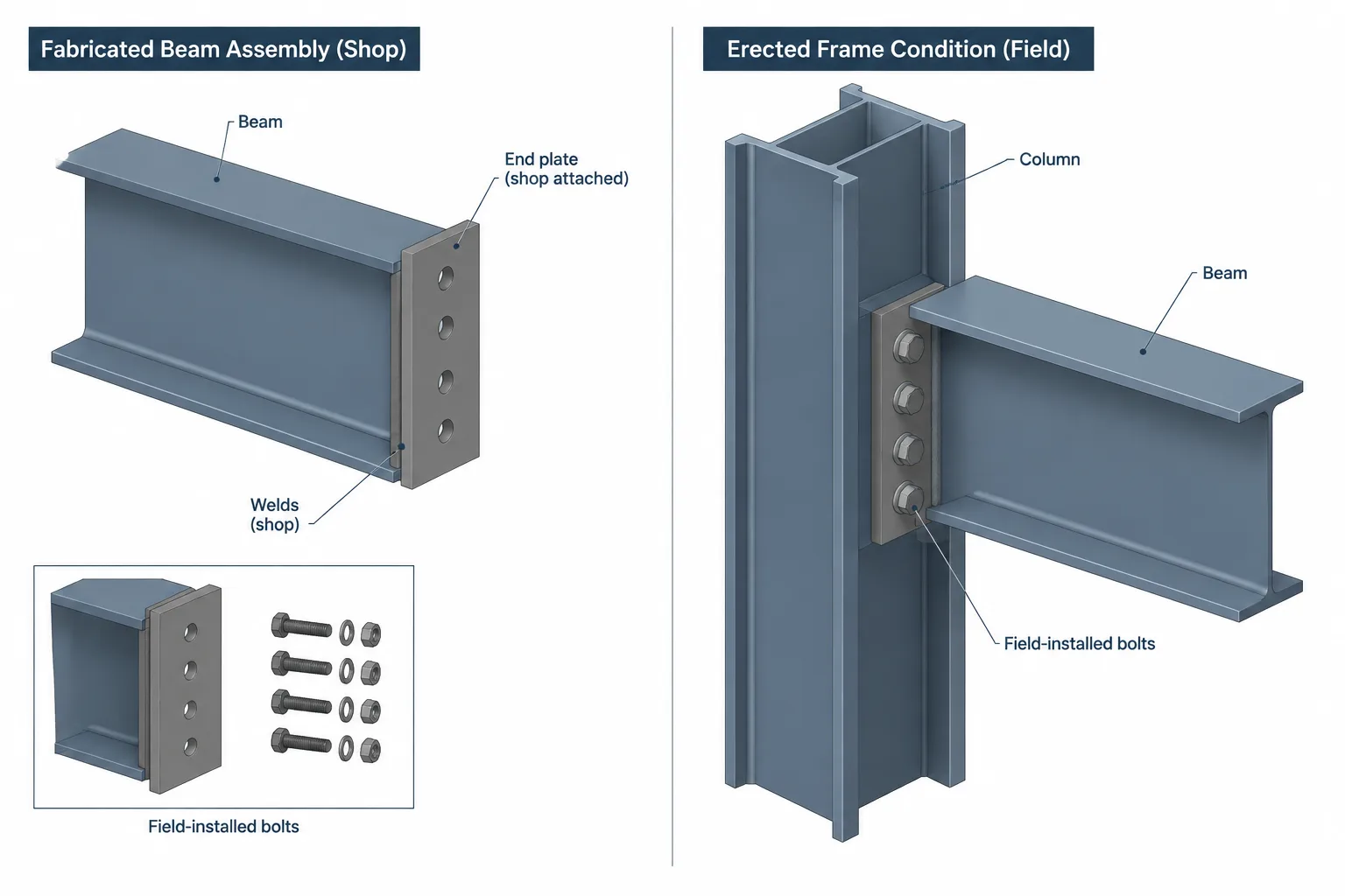
Framing-angle connections often combine shop and field operations. For example, an angle may be attached to one member during fabrication and connected to another during erection. However, the exact sequence and attachment method are project-specific.
Detailing should distinguish shop bolts, field bolts, shop welds, and field welds where applicable. This is not simply a notation issue. The selected attachment sequence affects whether the beam can be lowered, swung, or slid into place and whether workers can reach the required side of the connection.
For double-angle arrangements, determine whether both angles remain with the supported beam, both remain with the support, or the connection uses another erection strategy shown by the approved details. Avoid modeling a paired connection as a permanently closed pocket unless the intended erection path has been checked.
Beam-end geometry and fit
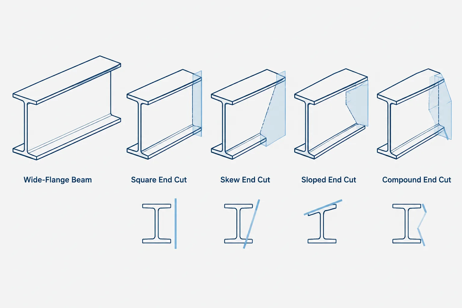
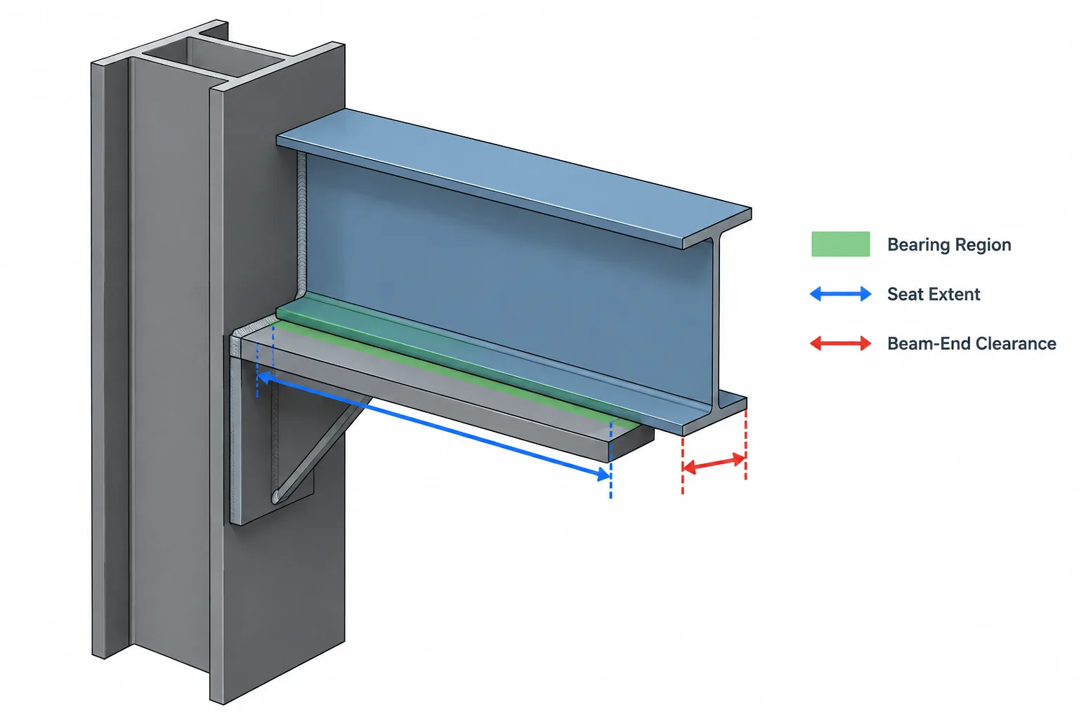
The supported beam end must fit between or beside the connection components without unintended interference. Important geometry includes the beam setback, available end clearance, flange-to-support clearance, cope geometry when present, and the relationship between angle length and the beam flanges.
The rolled root fillet of an angle is not a sharp internal corner. Likewise, the web-to-flange region of a rolled W-shape includes fillet geometry that may restrict where an angle, bolt head, weld, or plate can be placed. Simplified rectangular CAD outlines can miss these conflicts.
For double-angle connections, also check that the angles seat against opposite faces of the web as intended. Web thickness, coatings, fabrication variation, and connection tolerances are real fit-up considerations, but any required allowance must come from the governing project criteria rather than an invented CAD gap.
Bolt and weld information that must be explicit
A framing-angle detail should communicate more than the angle size and member marks. Depending on the connection, the required information may include:
- Angle quantity, length, orientation, and material identification
- Hole locations, hole types, and the members in which they occur
- Bolt diameter, installation side, and associated connection notes
- Weld location, extent, side, and whether it is a shop or field operation
- Beam setback and any cope or end-cut requirements
- Connection elevation relative to the supported and supporting members
- Near-side and far-side differences
Do not infer missing weld or bolt requirements from a generic CAD block. A reusable detail can provide drawing geometry, but the project-specific connection information must be verified.
Recommended drawing views
Elevation
An elevation is useful for showing angle length, vertical hole spacing, beam-end position, and the relationship to the support. For a single-angle connection, however, the elevation may not reveal which side of the web receives the angle.
Plan or horizontal section
A plan or section through the connection clearly shows the beam web, angle legs, support face, and near-side or far-side placement. This view is particularly valuable when checking bolt access and angle orientation.
End view
An end view can show whether a connection is single-angle or double-angle, how the angles bear against the web, and whether adjacent flange geometry restricts installation. Hidden lines should support the view rather than substitute for a clear section when the arrangement is congested.
CAD modeling and checking workflow
-
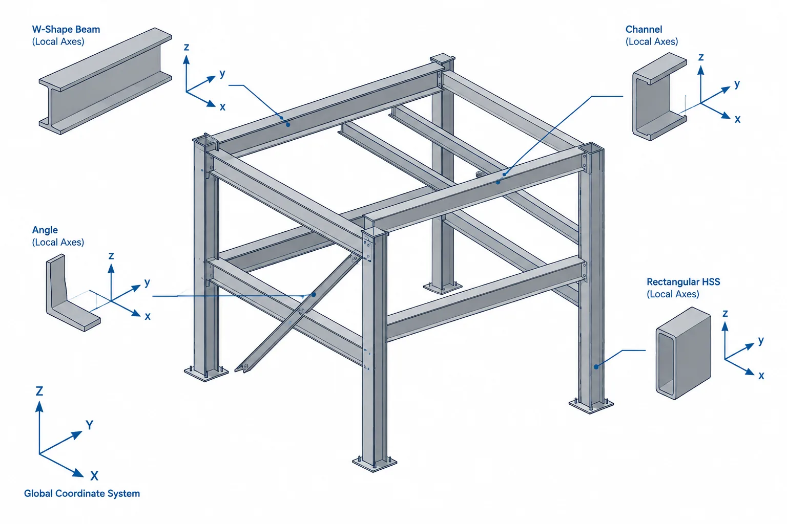
Establish member work lines and local axes. Confirm which direction is up, which end is being detailed, and which web face is near side.
-
Insert verified shape geometry. Use the correct beam, support, and angle profiles rather than relying on nominal bounding rectangles.
-
Place the connection from defined reference surfaces. Locate angles from beam-web faces and the support face, not from an arbitrary visual offset.
-
Model or draft holes in the correct parts. Coincident-looking circles do not prove that holes pass through the intended plies.
-
Check installation space. Review access for bolts, welds, and erection movement, including interference with flanges, stiffeners, plates, and adjacent members.
-
Create views from the final orientation. Avoid reusing a mirrored elevation without updating near-side, far-side, bolt, and weld information.
-
Compare with the connection design. Verify angle quantity, attachment method, hole arrangement, and member end geometry before issuing the detail.
Common detailing errors
- Showing a single angle without identifying the side of the web
- Assuming a double-angle connection is perfectly symmetrical
- Reversing the heel and toe orientation of an unequal-leg angle
- Drawing holes through the beam web but not through the corresponding angle leg
- Placing bolts too close to rolled fillets based on simplified linework
- Using a field-weld symbol where the intended operation is a shop attachment, or vice versa
- Ignoring the erection path created by preattached angles
- Mirroring a connection while leaving side-dependent notes unchanged
A geometry choice with design consequences
Single-angle and double-angle shear connections may look similar in elevation, but they are not interchangeable drafting options. Each arrangement creates a different physical relationship among the beam web, support, fasteners, welds, and erection space. The detailer’s task is to represent the specified connection accurately, make its orientation unmistakable, and identify potential fit or access problems before fabrication.
Shape tables and CAD profiles help establish reliable member geometry. They do not determine the required connection strength, attachment method, or suitability for a particular project. Those decisions remain subject to the governing design documents and qualified engineering review.