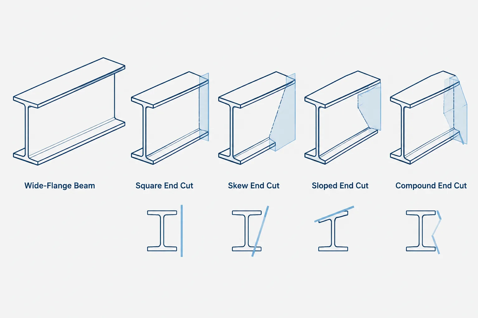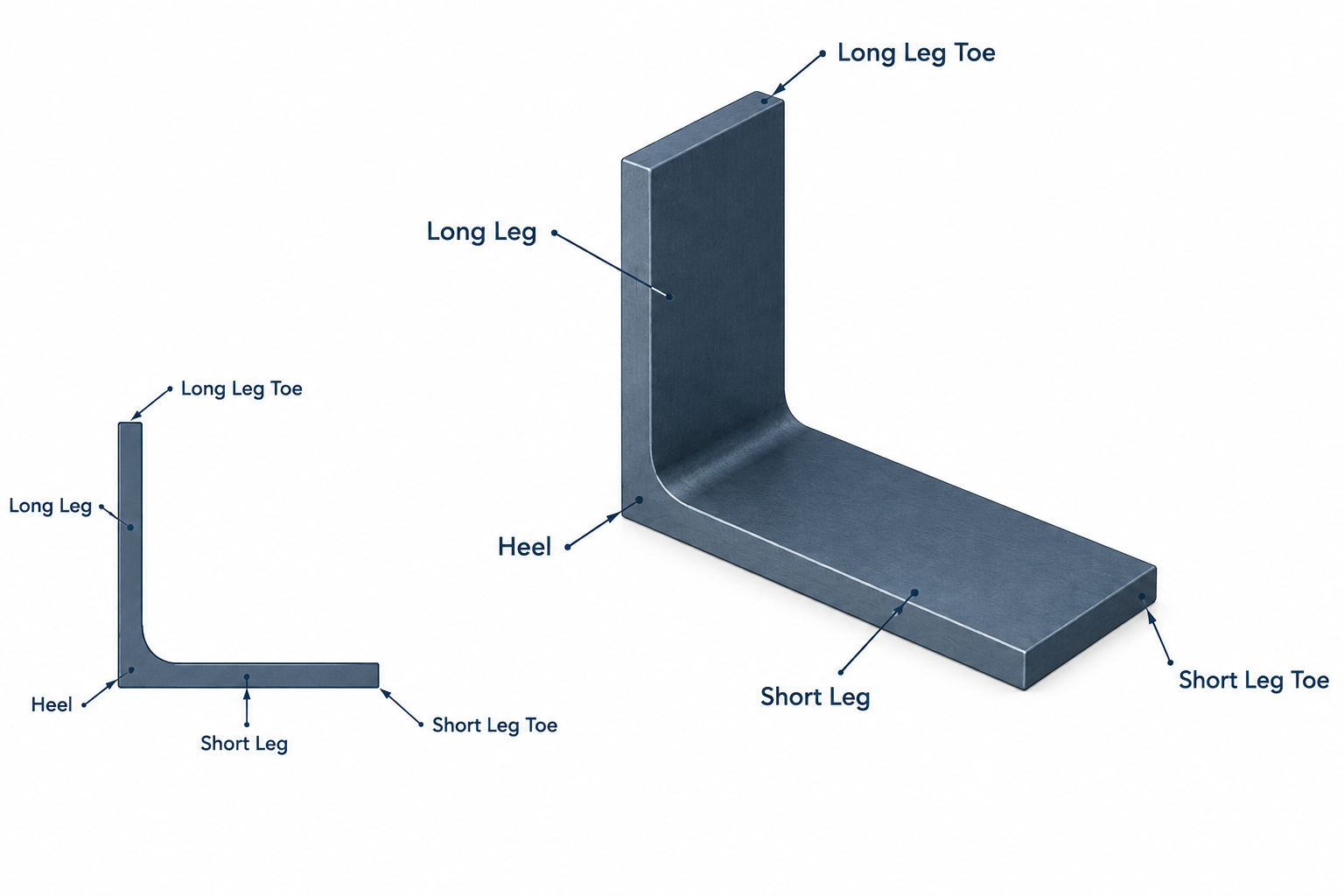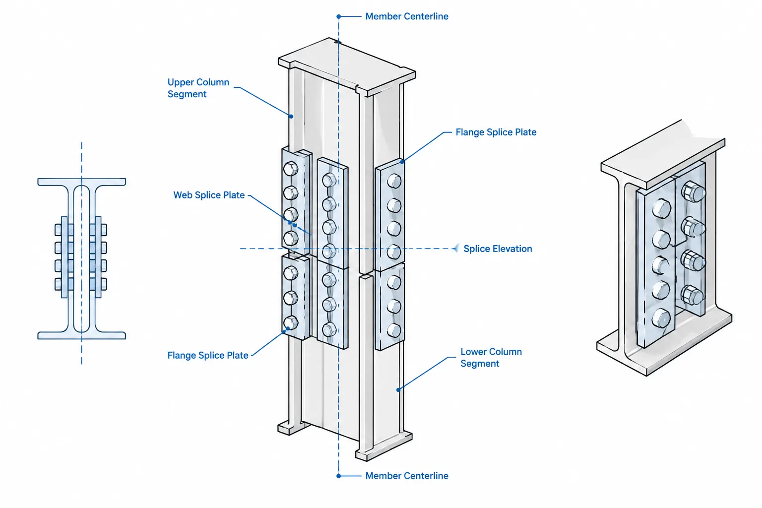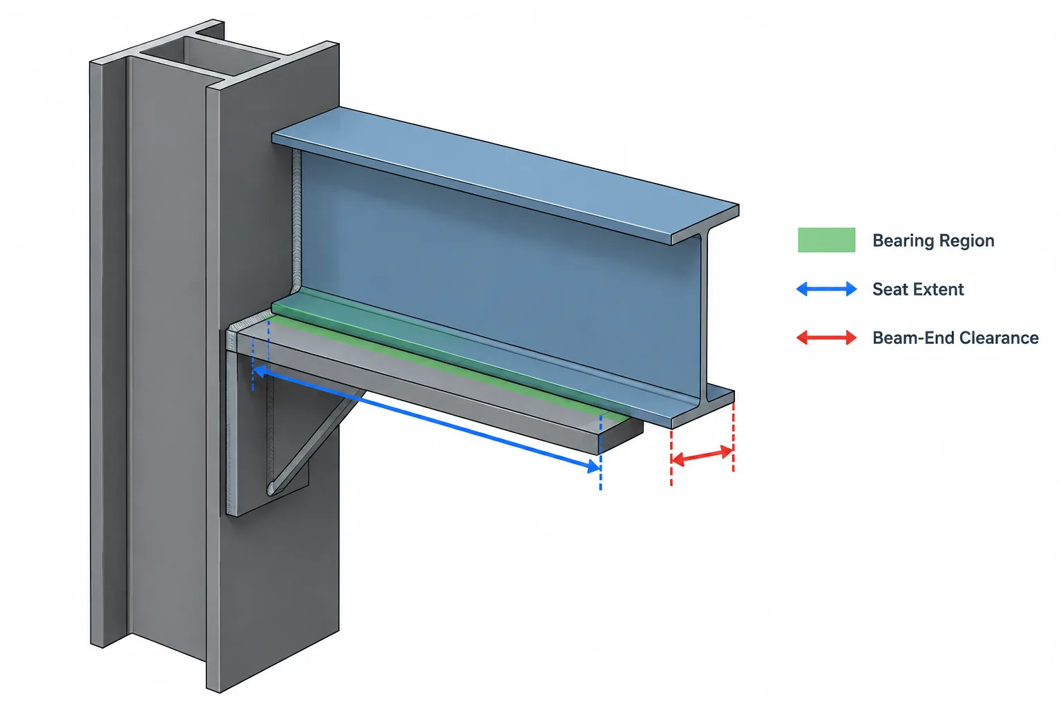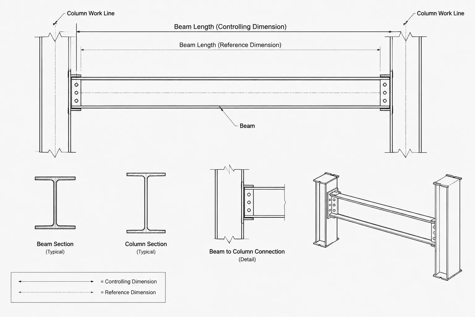
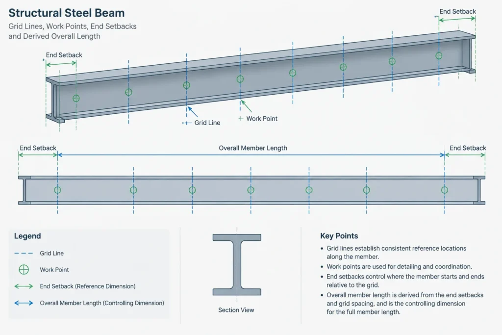
A structural steel drawing may show several dimensions that appear to describe the same geometry. One dimension locates a beam end from a grid line, another gives the distance between work points, and a third reports the resulting overall length. Although the numbers are related, they may not have equal authority.
Distinguishing controlling dimensions from reference dimensions is essential when detailing beams, columns, plates, bolt patterns, and welded assemblies. The distinction tells a fabricator which value establishes the geometry and tells a detailer which values must update when the model changes. It also helps reviewers identify conflicts instead of silently choosing the most convenient number.
What Is a Controlling Dimension?
A controlling dimension establishes the intended position, size, or relationship of an item. It drives the geometry rather than merely reporting it. Depending on the drawing and project conventions, controlling information might include:
- Grid-to-grid or work-point dimensions
- Member setbacks from defined work points
- Top-of-steel or bearing elevations
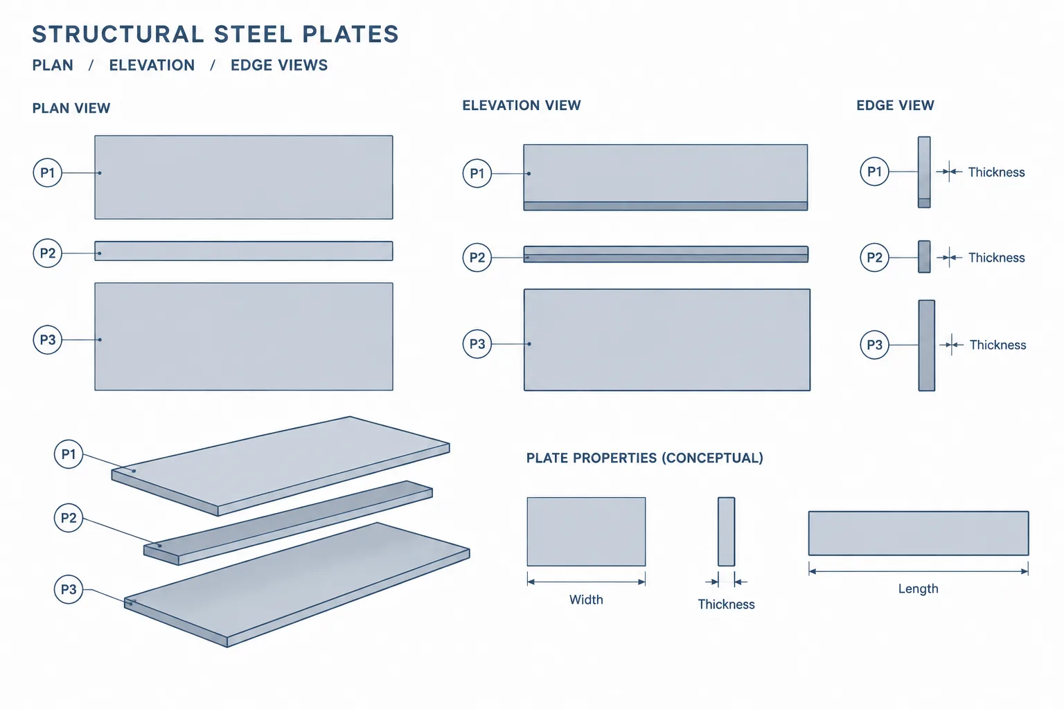
- Plate thickness, width, and length
- Bolt gage, pitch, edge distance, or end distance
- Connection material locations measured from a designated datum
- Specified slopes, angles, or offsets
A dimension is not controlling simply because it is printed prominently. Its role depends on the drawing hierarchy, established datums, project notes, design information, and detailing conventions. When that role is unclear, the correct response is coordination—not an assumption.
What Is a Reference Dimension?
A reference dimension communicates useful information derived from other controlling geometry. It may help with checking, material handling, fit-up, estimating, or understanding an assembly, but it ordinarily should not independently redefine the geometry.
Common examples include an overall dimension calculated from several controlled segments, a diagonal measurement added as a squareness check, or a clearance reported from two items whose positions are controlled elsewhere. Reference dimensions are sometimes displayed in parentheses, labeled as reference, or styled differently. However, presentation practices vary. Parentheses alone should not be treated as a universal substitute for understanding the drawing’s dimensioning convention.
Reference does not mean unimportant
A reference value can reveal a serious problem. If the reported overall length does not agree with the controlling setbacks and work-point distance, at least one item may be outdated or incorrect. The reference dimension may not govern fabrication, but the disagreement still requires resolution.
Controlling, Reference, Redundant, and Calculated Dimensions
These terms are related but not interchangeable.
| Dimension type | Primary purpose | Typical concern |
|---|---|---|
| Controlling | Establishes geometry from an accepted datum or requirement | Must be clear, complete, and coordinated |
| Reference | Reports a value derived from controlling geometry | Must update when the source geometry changes |
| Redundant | Repeats geometry already fully defined elsewhere | Can create conflicts if independently edited |
| Calculated | Results from geometry, formulas, or model measurements | May be controlling or reference depending on design intent |
| Check dimension | Supports verification during detailing, fabrication, or erection | Should have an identified basis and purpose |
A calculated dimension is not automatically a reference dimension. For example, a detailer may calculate the true length of a sloped member from controlling coordinates. Once reviewed and issued for fabrication, the resulting member length may become necessary production information. The calculation method and the dimension’s role are separate questions.
Choose a Clear Dimensional Datum
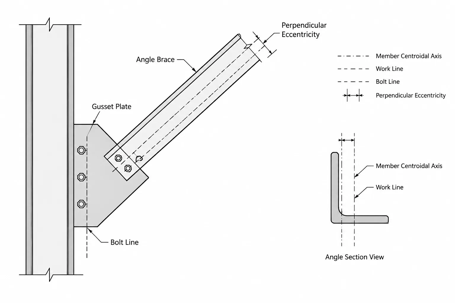
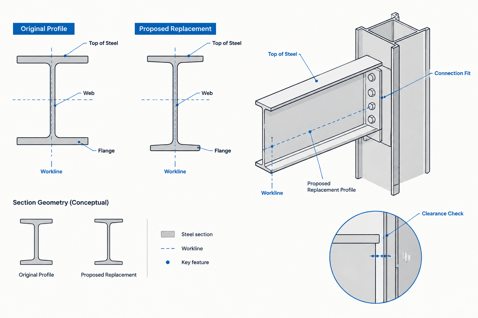
Reliable steel details are organized around identifiable datums. A datum may be a grid line, work point, column centerline, beam centerline, finished end, plate edge, top-of-steel elevation, or another stable reference.
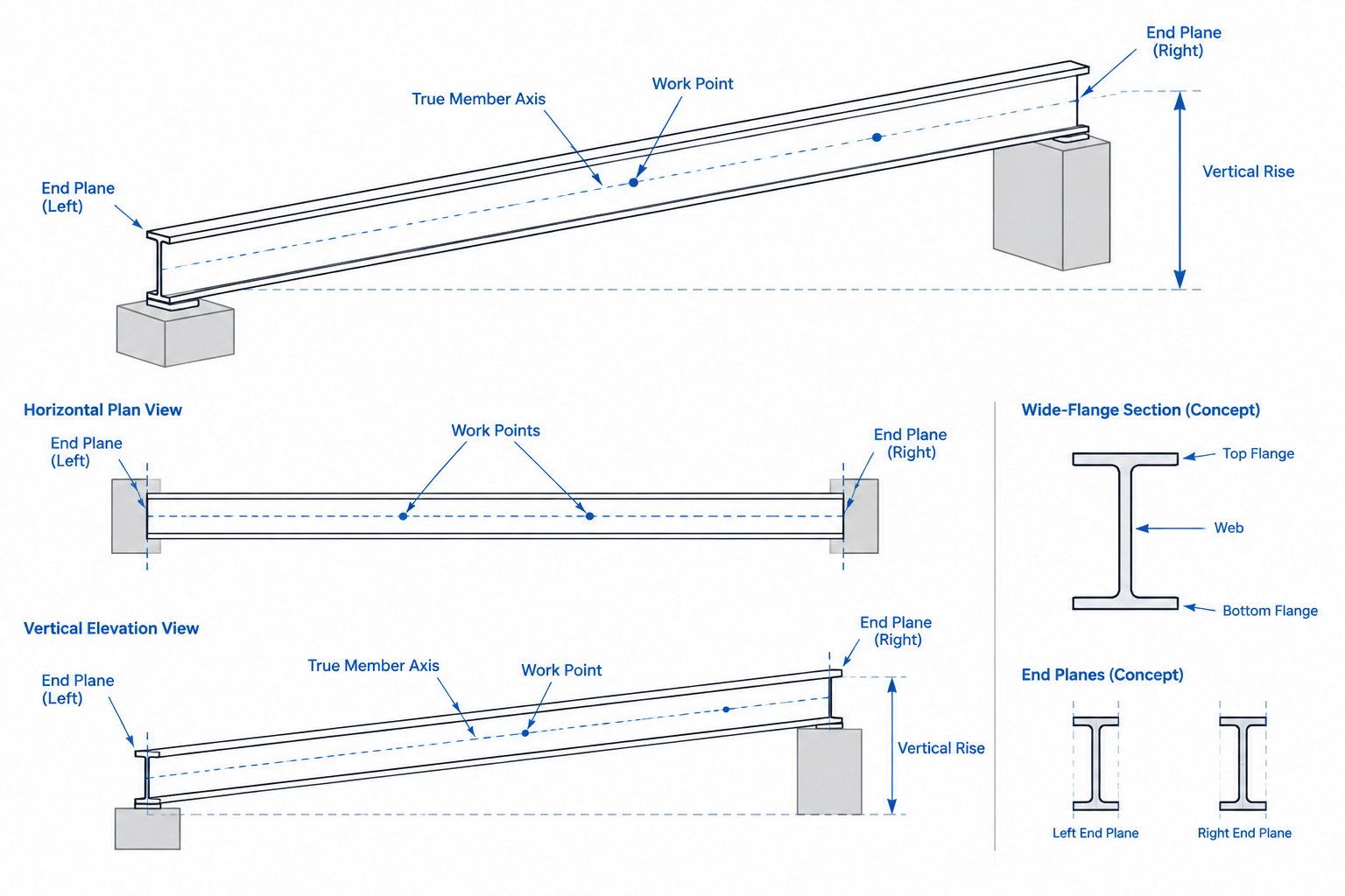
Consider a beam located between two column work points. Its geometry might be defined by the work-point distance and setbacks at each end. The resulting finished beam length is derived from those inputs. Alternatively, a project may control the finished member length directly and locate connection components from its ends. Either approach can be understandable when used consistently. Mixing both approaches without identifying priority creates ambiguity.
The preferred datum should remain stable through revisions. Dimensions taken from temporary construction lines, arbitrary CAD origins, or noncritical plate corners can become unreliable when connection geometry changes.
Avoid Closed Dimension Chains
A closed dimension chain occurs when every segment and the overall distance are all presented as if each independently controls the same geometry. If one value changes without the others updating, the drawing becomes mathematically inconsistent.
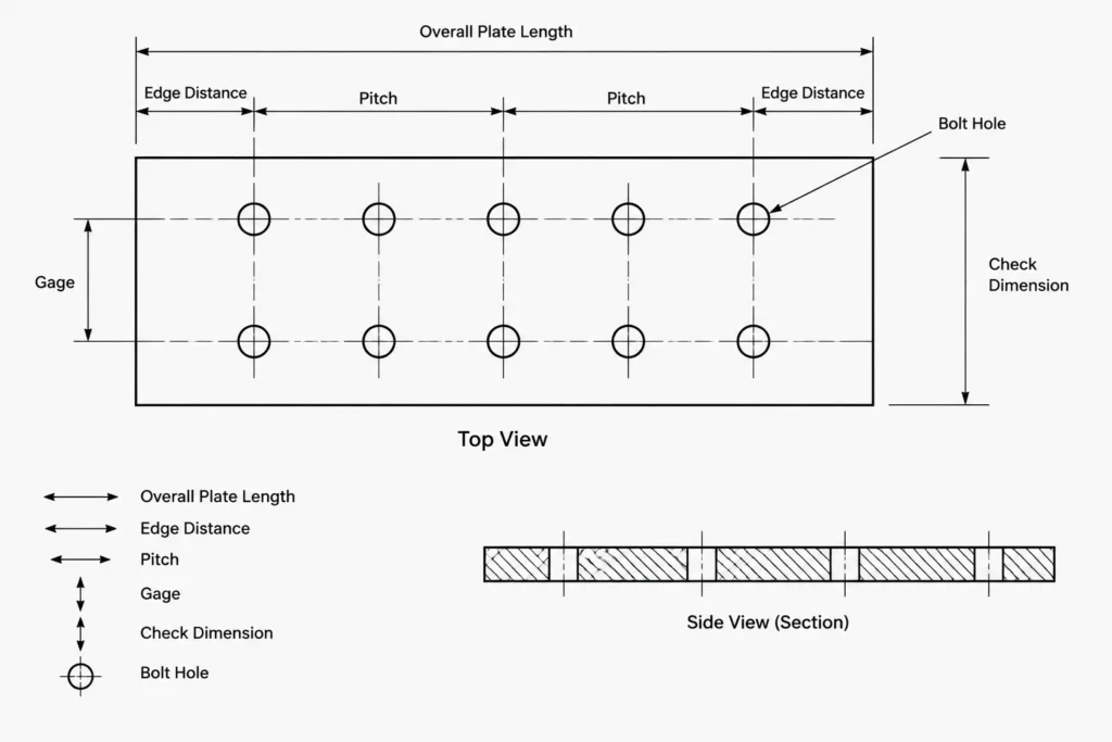
For example, a plate hole pattern might show the distance from the left edge to the first hole, every intermediate pitch, the final hole to the right edge, and the overall plate length. This information is useful, but all of it cannot independently control unless it remains perfectly coordinated. A clearer detail identifies the dimensions that establish the pattern and treats the remaining total or residual value as a check.
Closed chains are especially risky when dimensions are manually typed rather than associated with model geometry.
Applications in Common Steel Details
Beam length and end connections
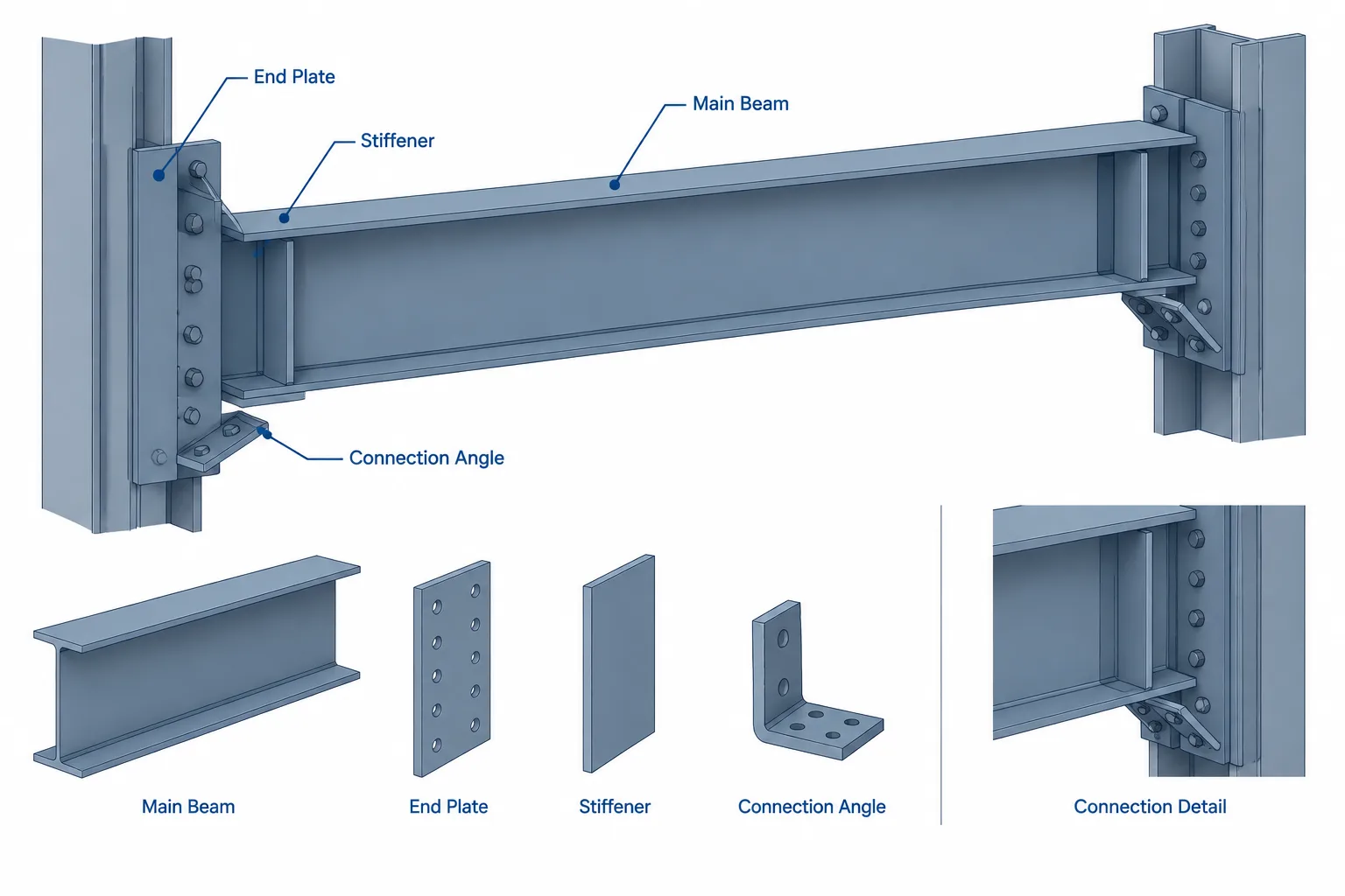
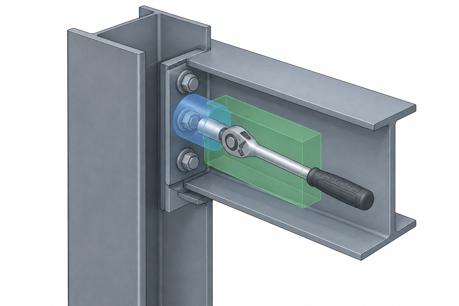
A beam detail may include work-point distance, end setbacks, finished length, cope locations, and connection plate positions. Determine whether connection material is located from the member end, the work point, or another datum. If the beam end changes, associated dimensions should update according to that intended relationship.
Bolt and hole layouts
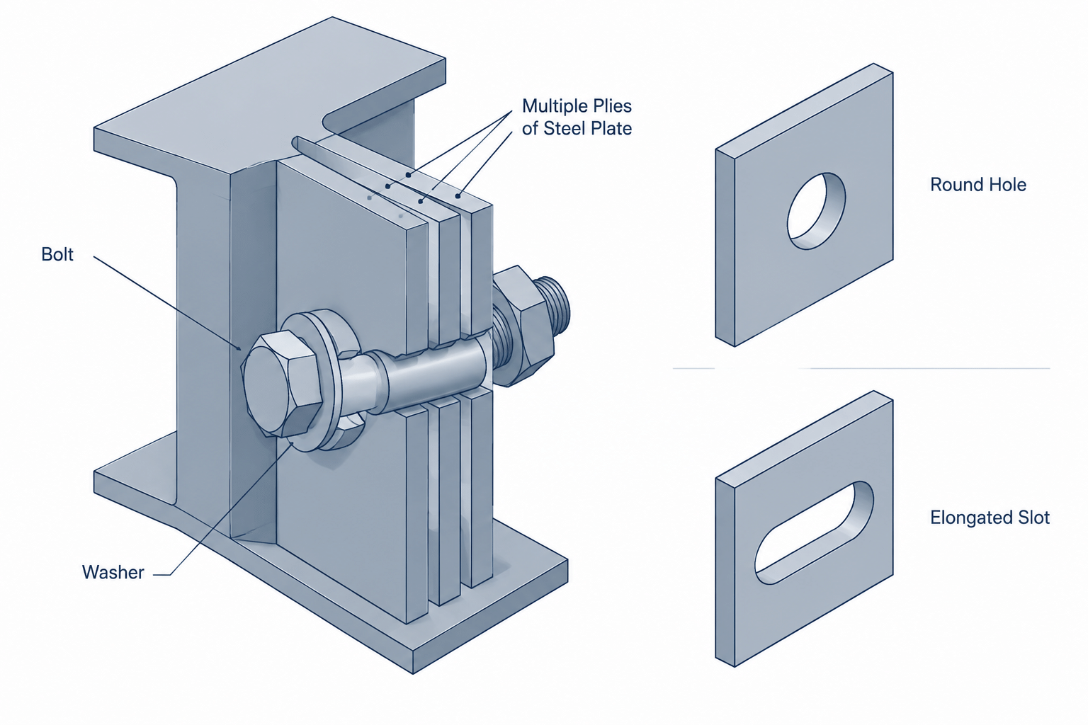
Hole patterns are commonly controlled by edge or end distances, gage, pitch, and a defined starting point. An overall distance between the first and last holes can be a useful shop check, but it should not conflict with the individual spacing values. Slots also require clear orientation and location; an overall bounding dimension alone may not define the actual pattern.
Base plates and anchor rods
Base plate details can contain column centerlines, plate centerlines, anchor-rod centerlines, edge distances, and overall plate dimensions. The drawing should make clear whether the anchor layout is centered on the column, centered on the plate, or offset from a project datum. Assuming that all three centers coincide can produce a serious coordination error.
Stiffeners and connection plates
A stiffener may be located relative to a beam end, column face, support work point, or load application point. Reporting its distance from a convenient nearby edge is useful only when that edge has a stable and intentional relationship to the required location.
CAD and Model-Based Dimensioning
Associative dimensions reduce transcription errors because displayed values follow the measured geometry. They do not determine design intent. A dimension can update perfectly and still be measured from the wrong points.
In a CAD or model-based workflow, classify dimensions by purpose before placing them:
- Identify the geometric datum and member work points.
- Define which inputs drive member ends, holes, plates, and connection material.
- Create geometry from those inputs rather than drawing approximately and dimensioning afterward.
- Add reference or check dimensions only where they improve communication.
- Use consistent layers, styles, notes, or other office-approved methods to distinguish dimension roles.
- Regenerate and review dimensions after revisions, substitutions, and connection changes.
Do not rely on scaling a plotted sheet or measuring a PDF when authoritative dimensions or coordinated model information should be available. Plotting, viewport scaling, rasterization, and file conversion can all affect apparent measurements.
Revision Control and Conflicting Values
Reference dimensions are frequent revision casualties. A controlling value is changed, but a manually entered overall dimension remains unchanged. The drawing then contains two plausible values.
When dimensions conflict, avoid selecting one based solely on convenience. Trace each value to its source:
- Is it tied to a design grid, elevation, or work point?
- Was it calculated from other dimensions?
- Is it associated with current geometry or manually overridden?
- Does it belong to a superseded connection condition?
- Do related plans, elevations, sections, and schedules agree?
Record and resolve the discrepancy through the project’s established review or clarification process. A neat CAD model does not remove the need to confirm intent.
Practical Drawing Review Checklist
- Can the controlling datum be identified without guesswork?
- Are member ends and connection components located from intentional references?
- Are overall dimensions consistent with their component dimensions?
- Are any closed dimension chains presented as independently controlling?
- Do parenthetical or labeled reference dimensions match current geometry?
- Have manually overridden dimensions been identified and checked?
- Will a revision to one controlling input update all dependent geometry?
- Do plan, elevation, section, and detail views describe the same condition?
- Are field and shop users likely to interpret the dimensional priority consistently?
Make Dimensional Intent Visible
Good steel detailing does more than provide enough numbers to reproduce a shape. It communicates which geometry matters, where measurements begin, and how related values were obtained. Controlling dimensions should establish the assembly from stable datums. Reference and check dimensions should improve verification without competing with that control.
When every displayed number appears equally authoritative, revisions and conflicts become harder to manage. A deliberate dimensional hierarchy makes shop drawings easier to review, CAD models easier to maintain, and fabrication information less vulnerable to silent assumptions.