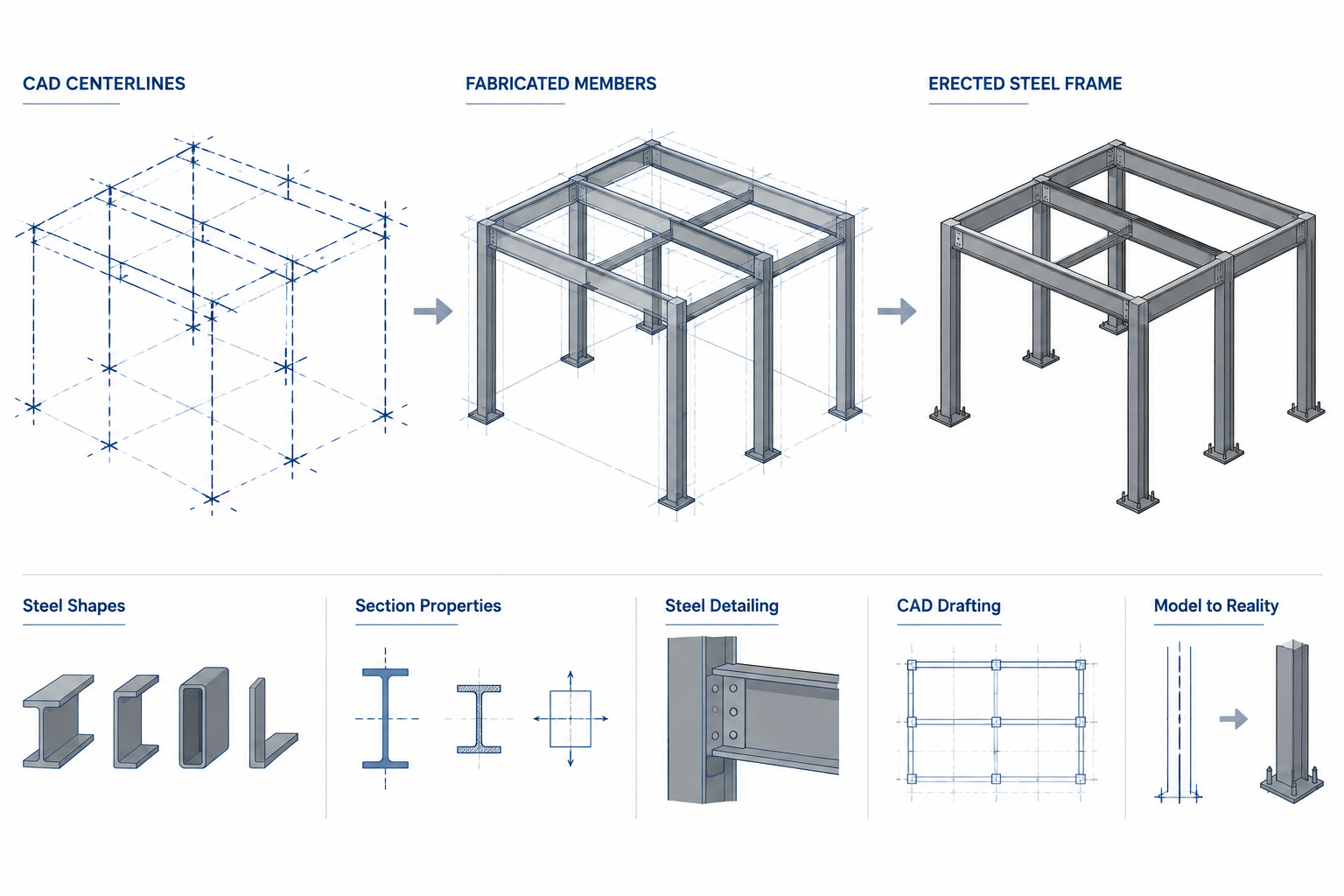
Structural steel drawings often present clean centerlines, square ends, exact elevations, and perfectly aligned holes. Real members cannot be produced and installed with mathematically exact geometry. The difference is managed through structural steel tolerances.
The word tolerance can refer to several different stages of a project. A rolled shape may vary within permitted mill limits, a fabricator may introduce variation while cutting and assembling it, and an erector may position the completed member within an allowed field range. These are related conditions, but they are not interchangeable.
Understanding which tolerance applies helps drafters avoid false precision, helps designers identify fit-sensitive details, and helps reviewers distinguish acceptable variation from an actual detailing or fabrication error.
What a tolerance means in steel construction
A tolerance is an allowed departure from a specified dimension, position, form, or alignment. It recognizes that manufacturing and construction processes produce controlled variation rather than exact geometry.
A tolerance is not the same as an intentional clearance. A slotted hole, erection gap, oversized opening, shim space, or adjustable connection may be deliberately detailed to accommodate expected variation. The clearance is part of the design geometry; the tolerance describes how far the finished work may vary from its specified condition.
Tolerances also should not be treated as automatic additions to nominal dimensions. For example, a modeler should not enlarge every rolled flange or shift every column by a presumed amount. Instead, the detail should be evaluated to determine whether permitted variation could interfere with fit, access, alignment, appearance, or performance.
The three main sources of variation
| Category | What it generally covers | Typical detailing concern |
|---|---|---|
| Mill tolerance | Variation in the manufactured steel product | Actual depth, flange shape, wall thickness, straightness, and cross-sectional form |
| Fabrication tolerance | Variation introduced while cutting, drilling, welding, fitting, and assembling | Member length, hole location, end preparation, camber, sweep, and attachment position |
| Erection tolerance | Variation in the installed position of members and assemblies | Column location, plumbness, beam elevation, alignment, and accumulated story-to-story position |
The governing limits depend on the product, project documents, referenced standards, fabrication method, connection type, and intended use. Current contract requirements should therefore be checked rather than relying on a general tolerance remembered from another project.
Mill tolerances: the shape is not perfect CAD geometry
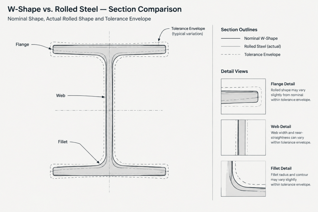
Steel shape tables list nominal or tabulated dimensions used for identification, design, and reference. The physical member delivered from a mill can vary within the limits applicable to that product.
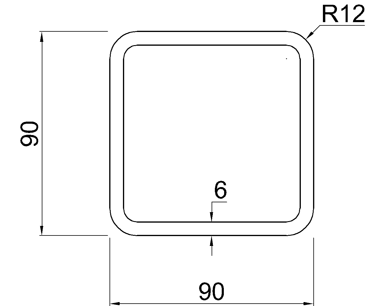
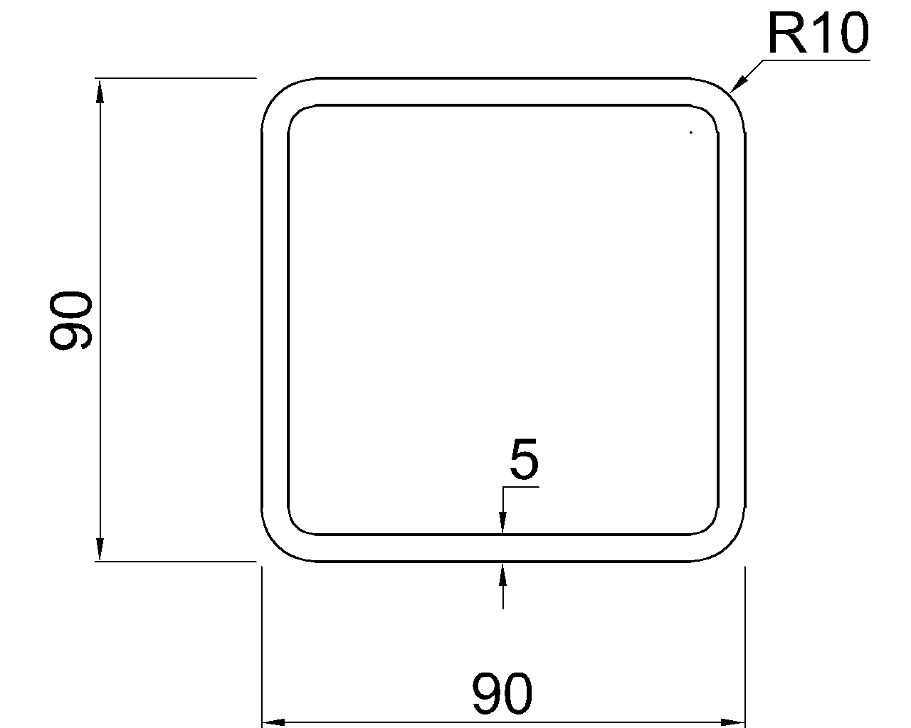
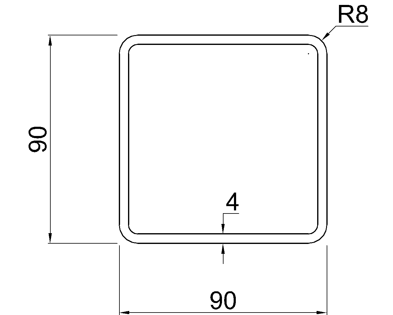
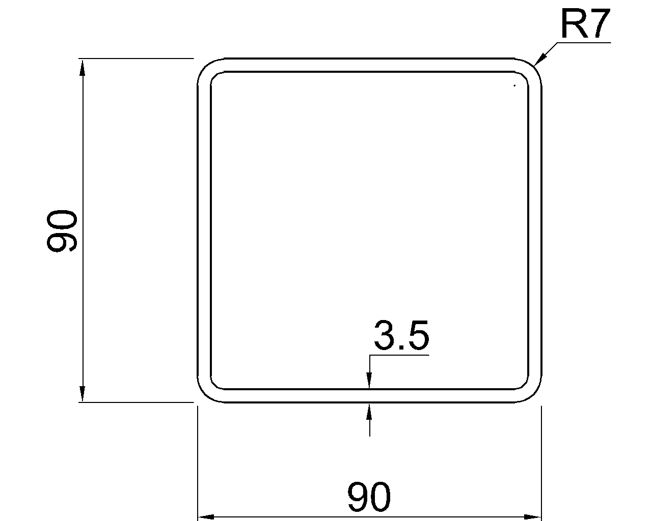
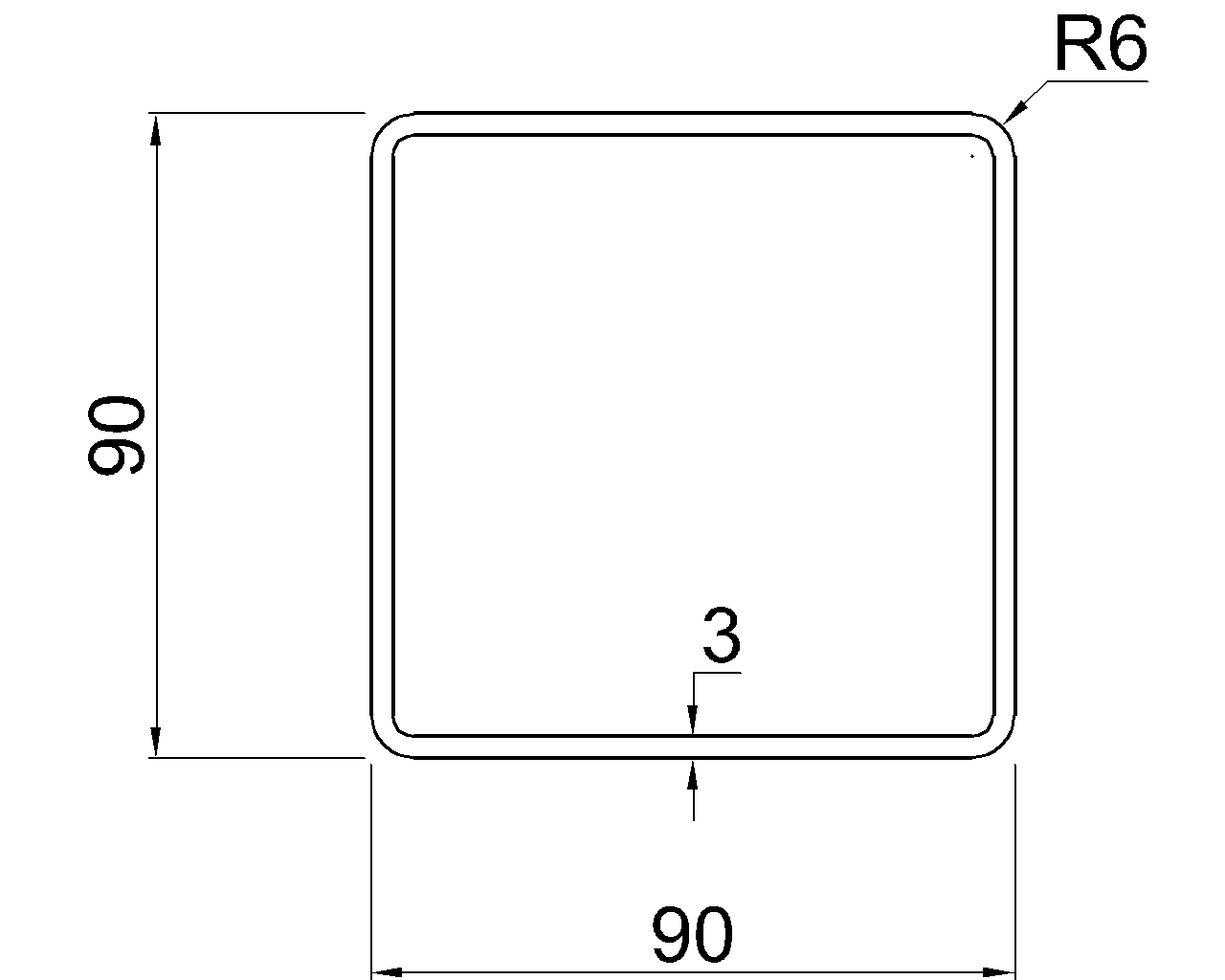
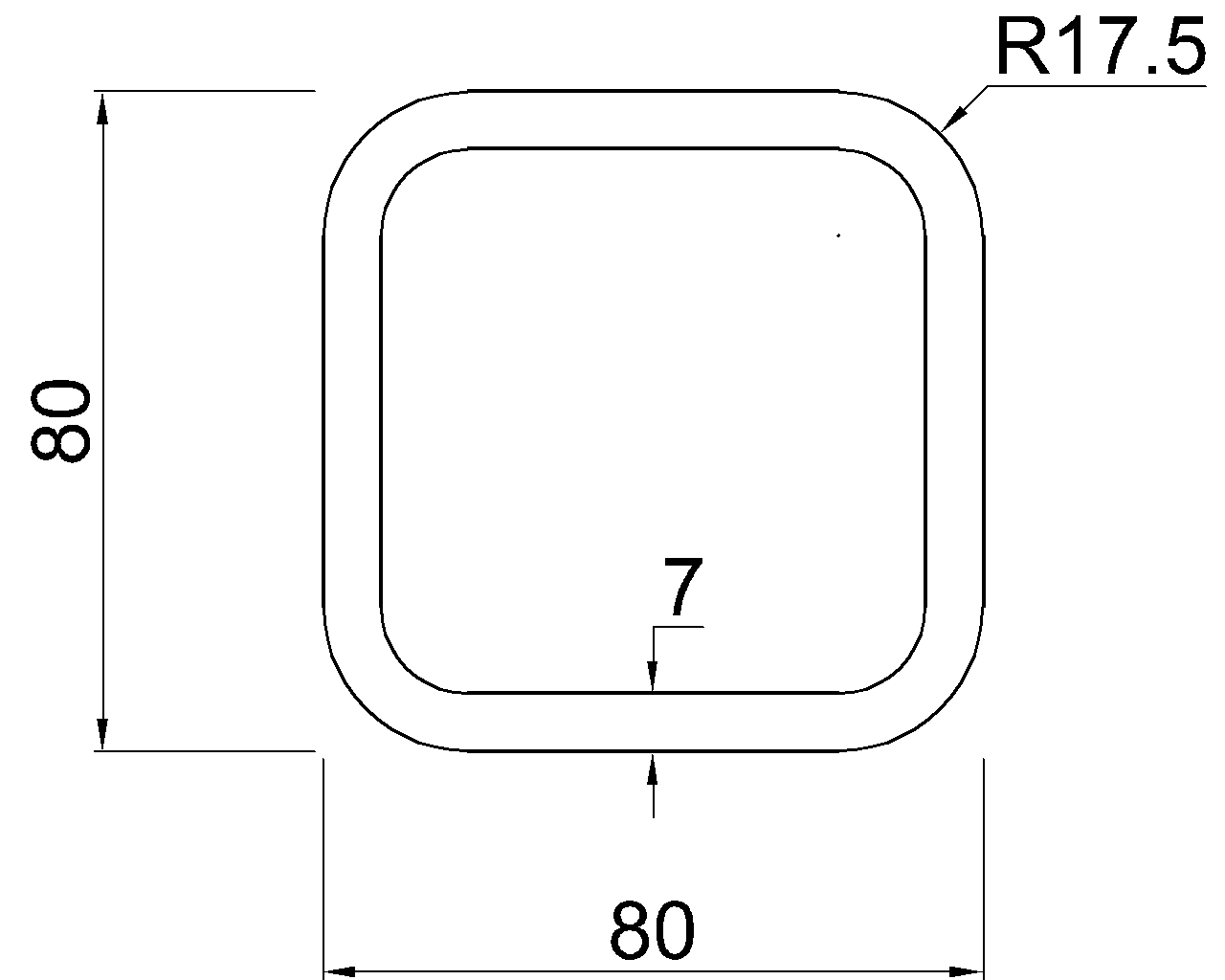
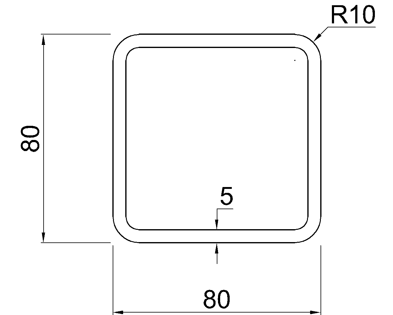
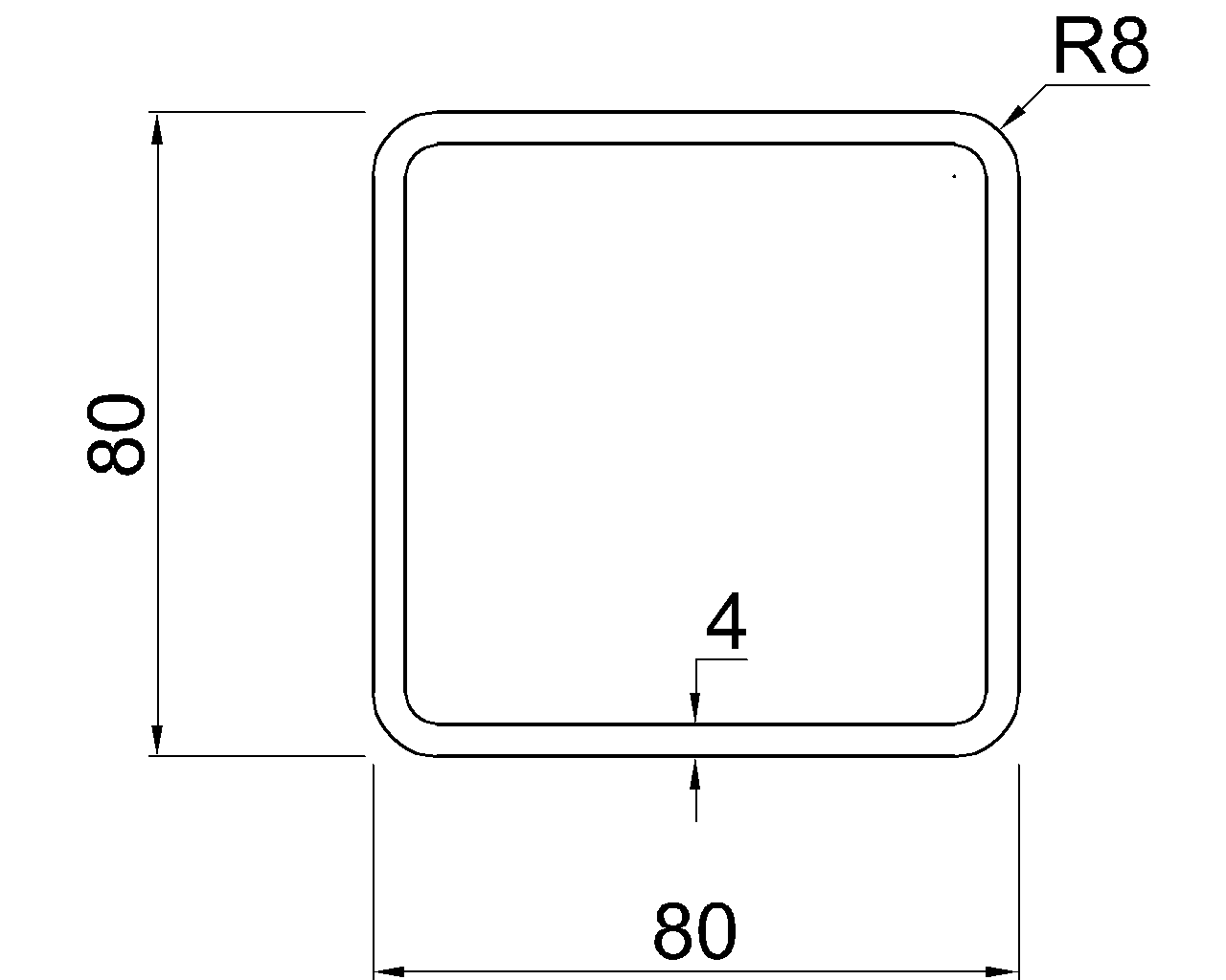
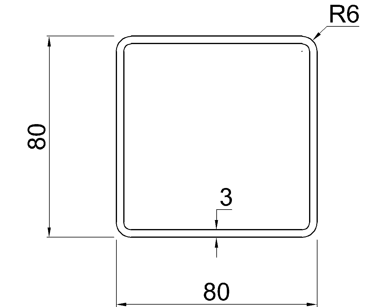
For a rolled W-shape, possible variation may involve overall depth, flange width, flange alignment, web position, straightness, and the local form of rolled surfaces. Flanges and webs are not machined plates, and rolled fillets are not sharp inside corners. For HSS, the outside dimensions, wall condition, corner geometry, straightness, and twist are relevant to fit-up.
Most general arrangement drawings do not need to depict these variations. A nominal section outline is normally the useful representation. Mill tolerance becomes important when another component closely surrounds, enters, bears against, or passes beside the steel shape.
Details that are sensitive to mill variation
- Plates fitted between W-shape flanges
- Connections placed close to flange-to-web fillets
- Sleeves or inserts intended to fit inside HSS
- Clamps or collars wrapping around a member
- Architectural covers with narrow, uniform reveals
- Machinery interfaces requiring controlled bearing or alignment
- Penetrations located close to section edges or rounded corners
In these situations, simply copying a nominal dimension from a database may not establish adequate fit. The detail may need clearance, field verification, selective fitting, machining, shims, or another adjustment method approved for the project.
Fabrication tolerances: variation within the shop process
Fabrication converts stock material into members and assemblies. Sawing, thermal cutting, drilling, punching, welding, bending, and handling can each affect final geometry. Welding is especially significant because heat input and weld shrinkage can change alignment even when the individual parts were initially positioned correctly.
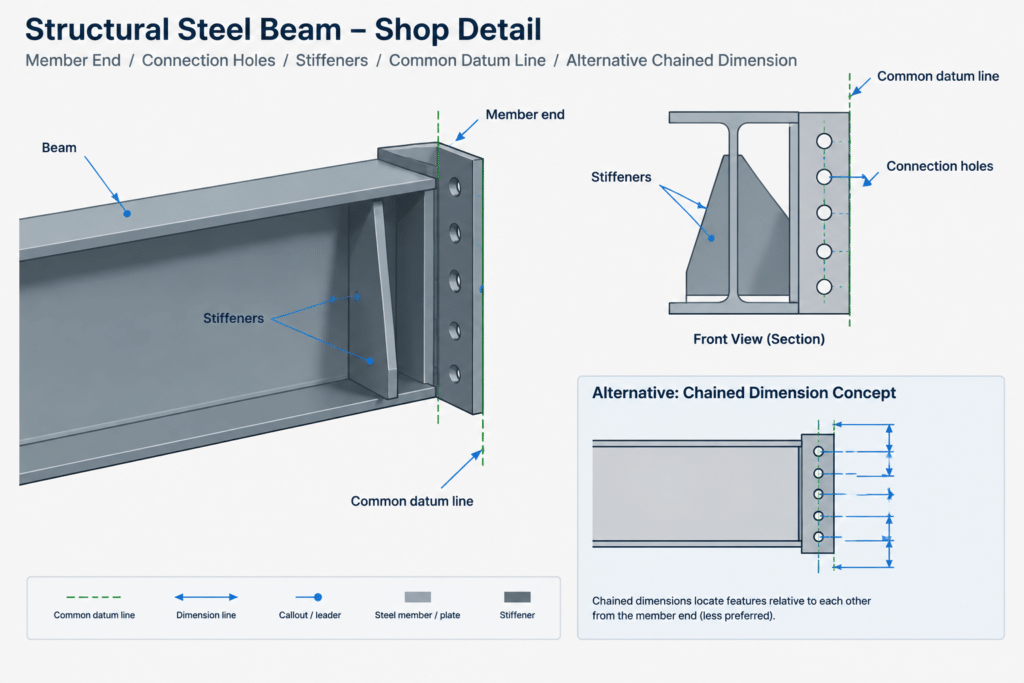
Shop drawings should establish dimensions from meaningful reference points rather than forcing the fabricator to derive critical locations from long chains of dimensions. Connection holes may be located from a member end, work point, face, centerline, or other defined datum. The best choice depends on how the part will be fabricated, assembled, and inspected.
A drawing filled with excessive decimal places does not create tighter fabrication. If a dimension is functionally critical, that requirement must be communicated through the project’s established documentation and coordinated with the applicable fabrication criteria. Precision in a CAD file is not, by itself, a tolerance specification.
Avoid uncontrolled dimension chains
Chained dimensions can accumulate variation. If several clip angles, stiffeners, or holes are each located from the preceding item, the final feature may drift relative to the member end or connection work point. Locating critical features from a common datum can reduce this problem.
This does not mean every dimension must originate from one end. It means the dimensioning strategy should reflect function. A beam-end connection may need to relate to the end cut, while an intermediate support attachment may need to relate to a structural grid or work point.
Erection tolerances: installed position is a range
During erection, members are positioned within a larger structure whose foundations, anchor rods, supporting steel, and adjacent construction already contain variation. Columns may not be perfectly centered on theoretical grid intersections, and beam elevations may not match an ideal model at every point.
Erection tolerances address installed conditions such as position, elevation, alignment, and plumbness. They do not excuse an incompatible detail. Connections need enough adjustability to be assembled while the supporting and supported members remain within their permitted ranges.
Common accommodation methods include holes that allow practical bolt insertion, shims or fill plates where permitted, adjustable edge distances in noncritical interfaces, closure plates, and field-measured components. The selected method must remain consistent with the engineered connection and project requirements.
Tolerance accumulation at interfaces
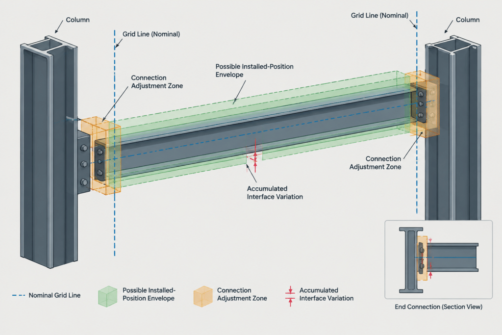
Fit problems often occur because several acceptable variations combine at one location. Consider a beam framed between two columns. The actual condition may reflect column position, column plumbness, beam length, end-connection location, supporting-member geometry, and erection sequence. Evaluating only the beam’s fabrication variation does not capture the full interface.
The most unfavorable combination should not automatically be assumed for every ordinary detail, but tolerance accumulation deserves explicit review where there is little adjustment capacity or where failure to fit would be costly.
Interfaces that deserve special coordination
- Steel connected to precast or cast-in-place concrete
- Anchor rods engaging base plates with limited adjustment
- Steel supporting curtain walls, glazing, stairs, or equipment
- Long runs of architectural exposed structural steel
- Members installed between two fixed supports
- Renovation work connected to an existing structure
- Shop-installed assemblies that must align with field-installed components
How to represent tolerance in CAD and BIM
A structural model is usually built from nominal geometry and theoretical work lines. This is appropriate for coordination, quantity work, drawing production, and design communication. Modeling random deformation or arbitrary dimensional variation generally makes the model less useful rather than more realistic.
Instead, CAD and BIM workflows should identify tolerance-sensitive zones. These can be managed with clearance envelopes, clash rules, reference planes, notes, interface details, or reserved adjustment space. A clearance envelope should be kept conceptually separate from the steel solid so users do not mistake it for actual member geometry.
For existing construction, field survey information should also be separated from the nominal design model. Point-cloud or measured geometry may represent the observed condition, while design centerlines represent the intended structural system. Both can be useful, but they answer different questions.
A practical detailing review
Before issuing a fit-sensitive steel detail, review the following questions:
- Is the referenced shape geometry nominal, measured, or minimum-clearance geometry?
- Which component controls the interface?
- Are dimensions taken from clear and repeatable datums?
- Can permitted variation accumulate from both sides of the connection?
- Is there room for bolt installation, welding, coating, and inspection?
- Does the detail depend on a sharp corner where the product has a fillet or radius?
- Can the assembly be adjusted with holes, shims, gaps, or field-fit pieces?
- Would field verification be more reliable than assuming existing geometry?
- Are any special limits clearly established in the contract documents?
Use tolerances to guide detailing, not to replace judgment
Structural steel tolerances are part of the production and erection process, but a list of allowable deviations cannot make an inflexible detail constructible. Good detailing starts with nominal geometry, recognizes where real variation matters, and provides a deliberate path for assembly and adjustment.
When fit is critical, confirm the applicable product, fabrication, and erection requirements for the project. Then coordinate the connection geometry, datum strategy, clearances, and inspection needs. That approach is more reliable than adding arbitrary gaps or assuming that exact CAD geometry will appear in the shop and field.