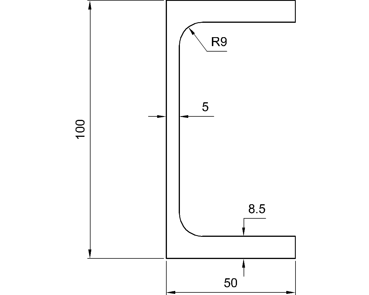
J 127x114x29 is a taper-flange joist section reference for engineers, detailers, fabricators, and steelwork researchers. This page brings together the section designation, listed dimensions, sectional area, unit weight, and standard reference in one practical location.
Use the entry alongside related resources on structural steel shapes, section properties, and steel connection detailing. The downloadable DWG can also support drafting workflows, subject to checking the file against the project specification and the governing design information.
J 127x114x29
Joists With Taper Flange Sections
refer to : EN 10365:2017
a European standard that defines the dimensions, tolerances, and sectional properties for hot-rolled steel channels, I-beams, and H-beams used in construction and engineering. It ensures uniformity and compatibility across European structural steel products.
Dimension : 127×114.3×10.2×11.5
Depth : 127 mm
Width : 114.3 mm
Web Thickness : 10.2 mm
Flange Thickness : 11.5 mm
Root Fillet Radius : 9.9 mm
Toe radius : 5 mm
Flange slope : 14.05%
Sectional Area : 36.8 cm2
Unit Weight : 28.9 kg/m
How to read the J 127x114x29 reference
The designation identifies a joist with taper-flange geometry. The source data separates the overall section dimensions from the web, flange, root, and toe details, making it easier to compare this shape with other entries in a steel-shape library.
- Dimension: summarizes the principal section dimensions in the order shown by the source.
- Depth and width: describe the overall envelope of the section.
- Web and flange thickness: identify the thicknesses of the principal plate elements.
- Root and toe radii: describe the curved transitions and edge geometry that affect detailing and accurate drafting.
- Flange slope: indicates the tapered flange profile rather than a parallel-flange arrangement.
- Sectional area and unit weight: are useful reference values for material takeoff and preliminary comparisons, but project design requires the applicable material, loading, stability, and connection checks.
Standard and CAD reference
The source cites EN 10365:2017 for the dimensional and sectional reference. When using this entry in a drawing or model, compare the required section designation, units, tolerances, material specification, and project revision requirements before issuing documents.
The linked DWG is intended as a drafting resource. Check its geometry, insertion units, layer conventions, and file condition before incorporating it into production drawings. Related pages on CAD and DWG steel references, structural steel terminology, and European steel sections can provide useful context.
Frequently asked questions
What type of section is J 127x114x29?
It is listed as a joist with taper-flange geometry. The page provides its dimensional and sectional reference data for engineering and drafting use.
Which standard is referenced for this section?
The source references EN 10365:2017, which is used here as the dimensional and sectional reference for the listed steel shape information.
What information is included for J 127x114x29?
The entry includes the principal dimensions, web and flange thicknesses, root and toe radii, flange slope, sectional area, and unit weight.
Can the DWG be used directly for fabrication?
The DWG should be treated as a reference drawing. Verify its geometry and units against the project specification, approved design documents, and fabrication requirements before use.
Do the listed properties replace structural design checks?
No. The listed values support reference and preliminary coordination. A qualified engineer must verify the section for the applicable loads, stability conditions, material requirements, connections, and detailing constraints.