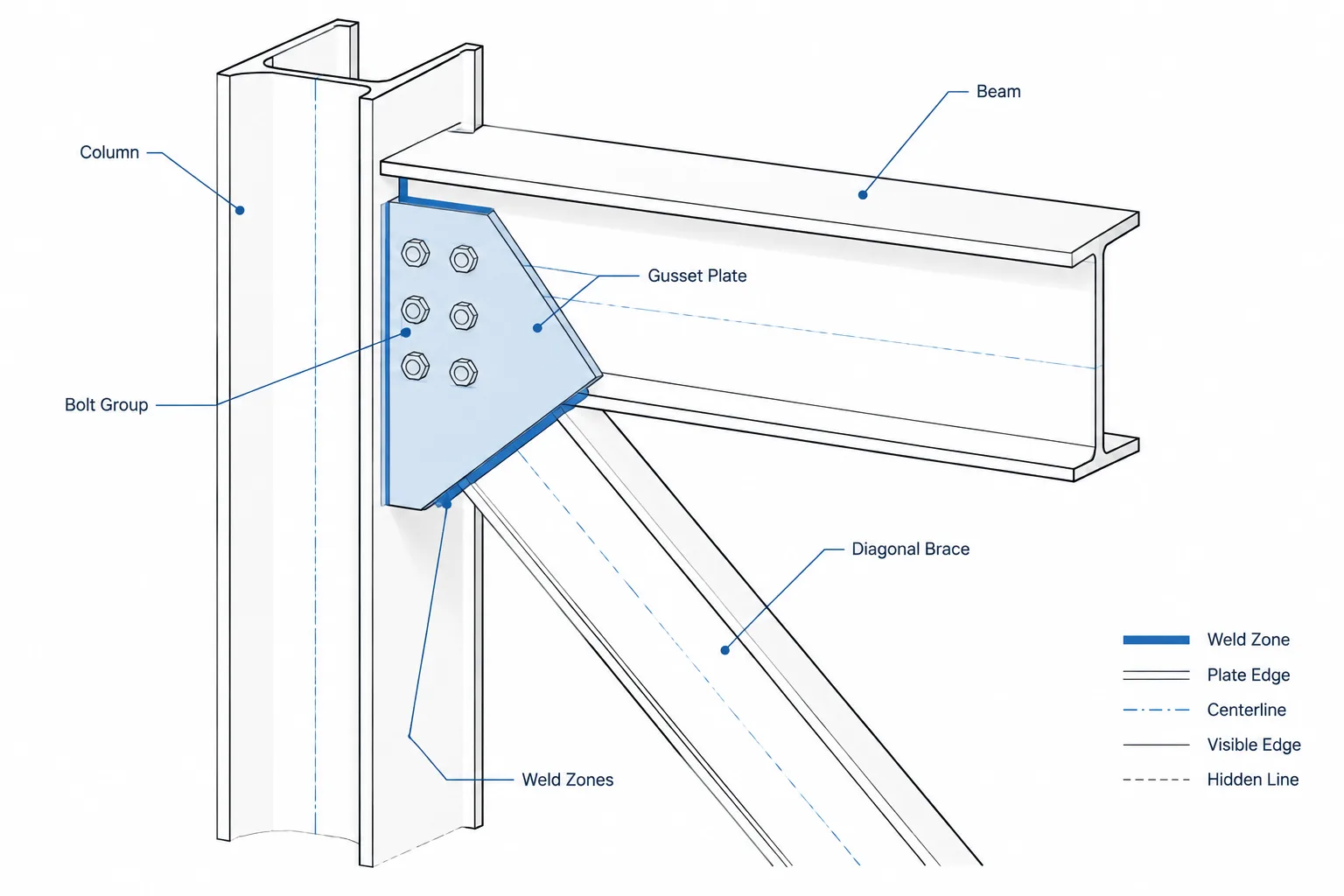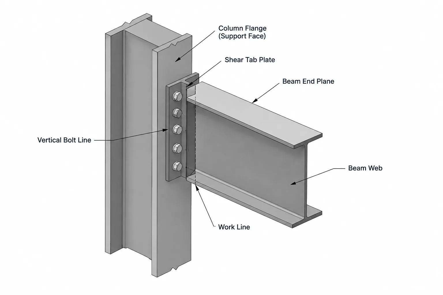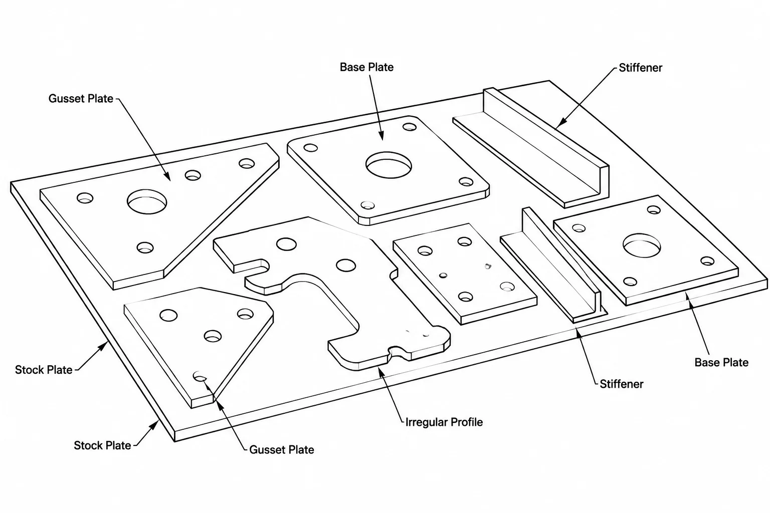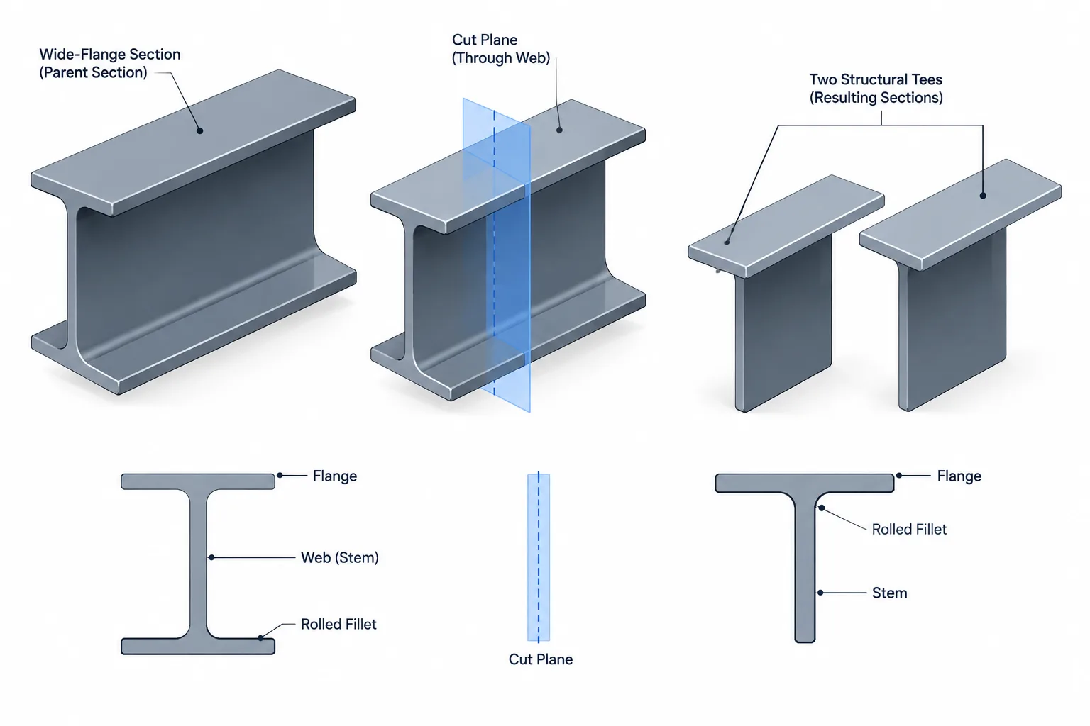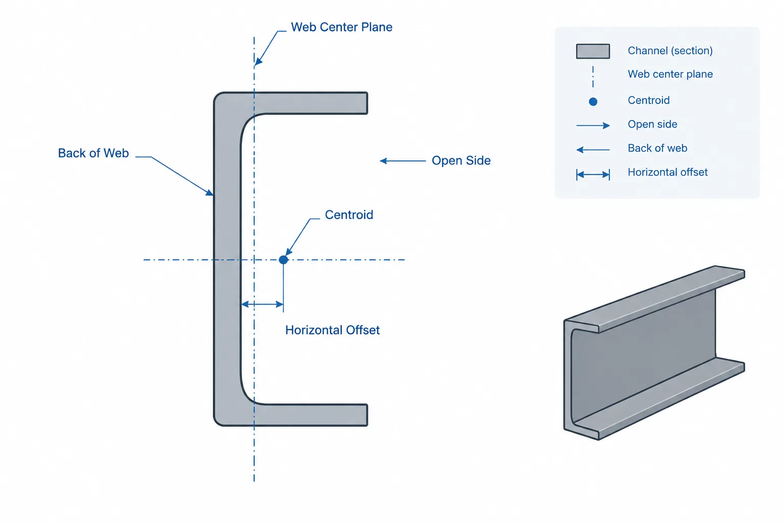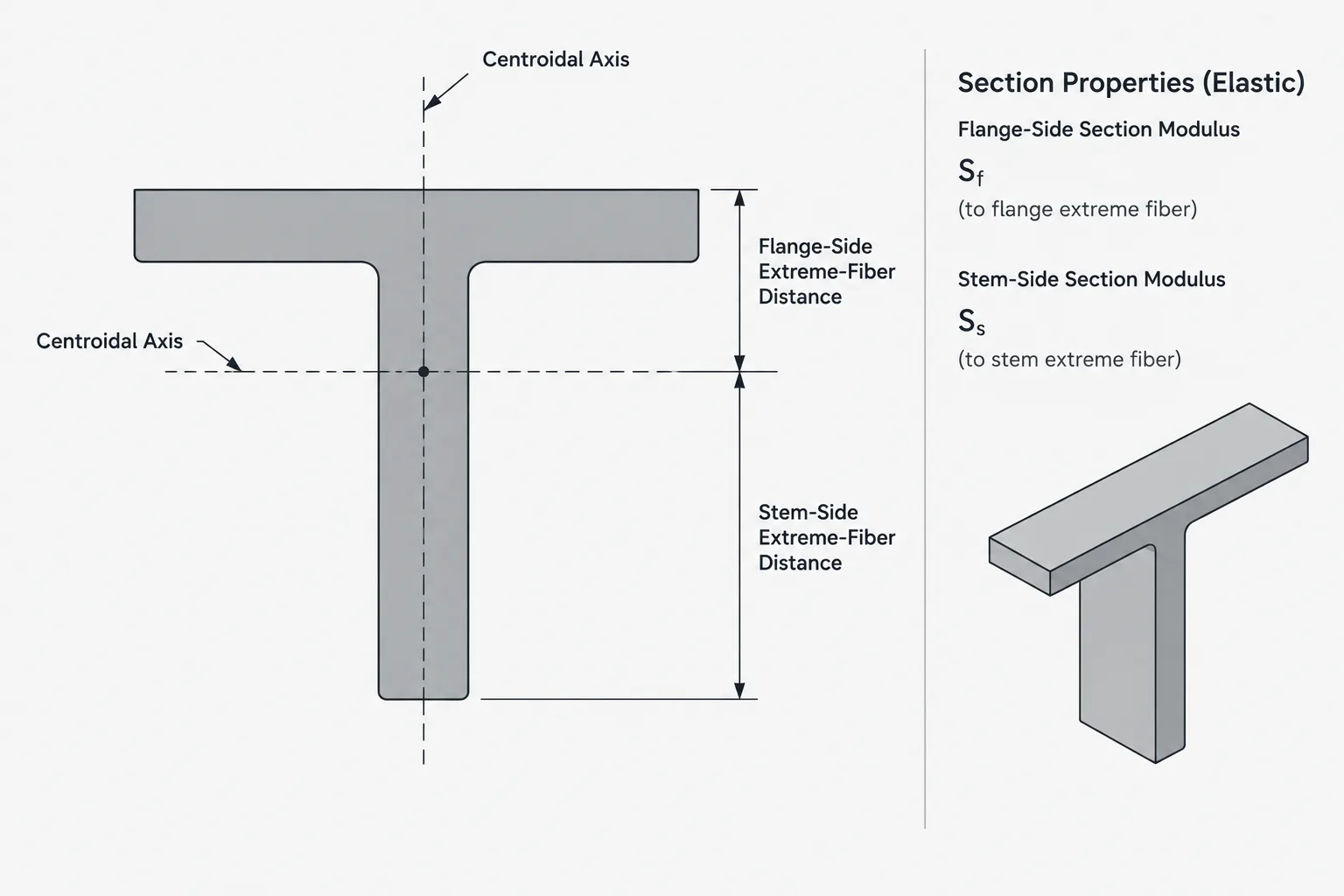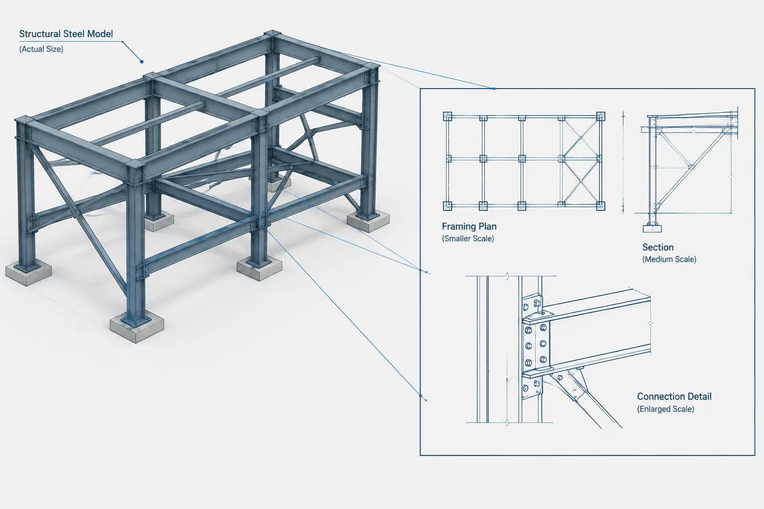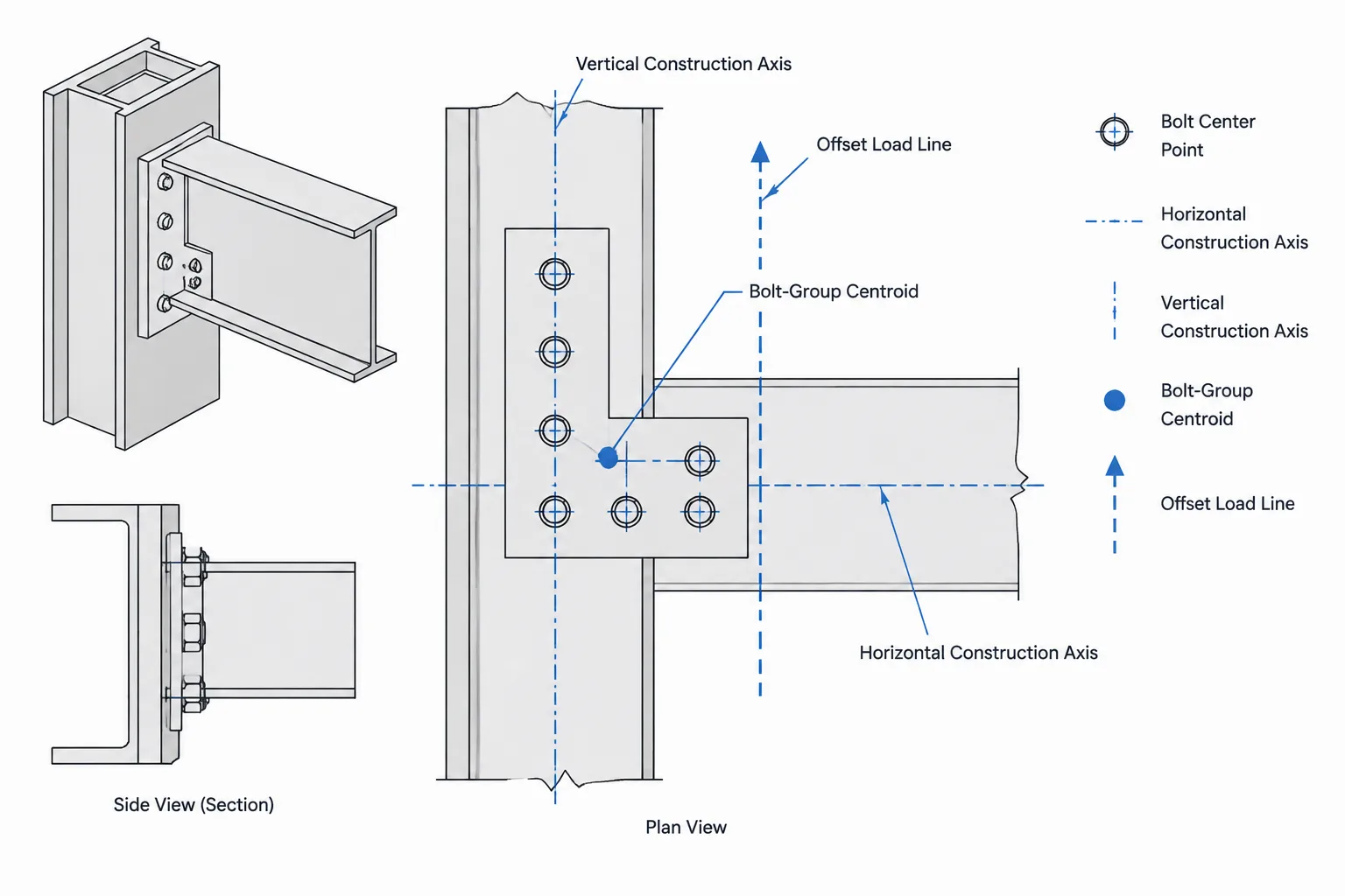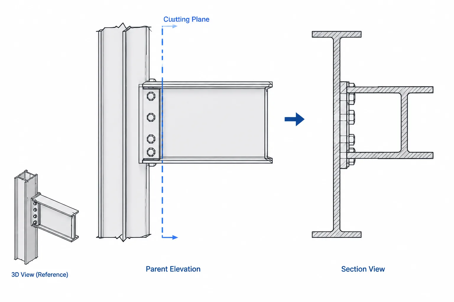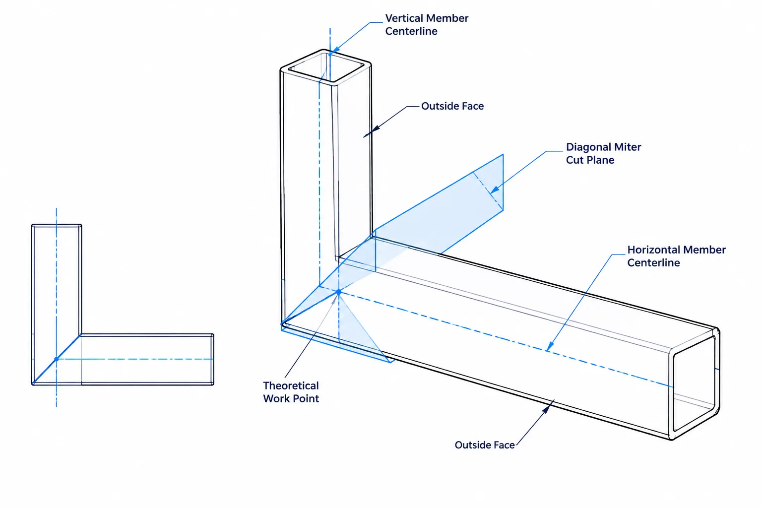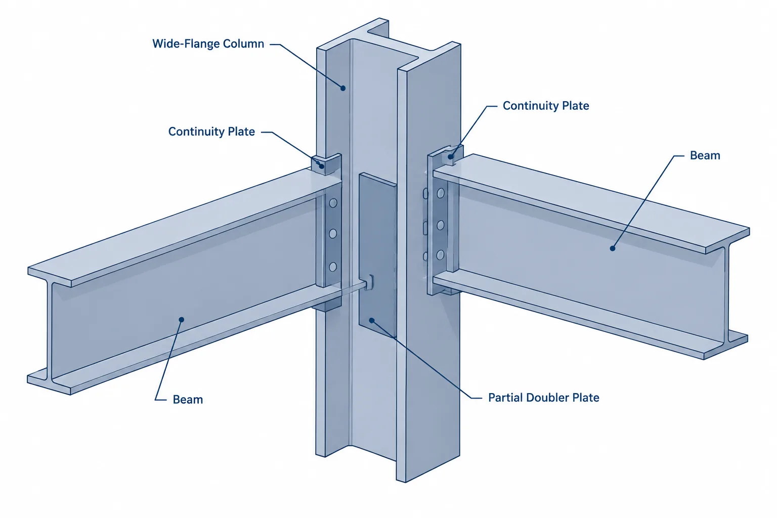
Continuity plates are transverse plates placed inside or across a steel column at a beam-to-column connection. They are commonly associated with moment connections, where beam-flange forces must pass into the column without overstressing or excessively deforming local portions of the column.
Although the structural engineer determines whether continuity plates are required and establishes their design, the plates also create important detailing questions. Their position must correspond to the actual beam-flange geometry, their edges must fit the column shape, and their welds must remain accessible. When beams frame into both sides of a column, the detailer must also determine whether the connection geometry truly aligns or requires separate plate levels.
This guide focuses on those geometric and coordination issues rather than plate design or connection capacity.
What a Continuity Plate Does
A beam in a moment connection transfers tension and compression through its flanges. At a wide-flange column, those concentrated forces enter the column near its flanges and web. A continuity plate helps distribute the force through the column cross section and restrain local deformation in the connection region.
Continuity plates may resemble column stiffeners, and the terms are sometimes used interchangeably in project conversations. In a moment-connection context, however, “continuity plate” usefully identifies a transverse plate associated with continuing beam-flange force through the column. It should not be confused with a doubler plate, which reinforces the column web panel zone rather than directly extending the beam-flange line across the section.
Start with the Beam-Flange Force Line
The most important geometric reference is not simply the beam centerline. It is the level and position of the beam flange delivering force into the column.
A typical elevation should be checked for:
- Beam top-of-steel elevation
- Actual beam depth
- Top- and bottom-flange thicknesses
- Connection end geometry
- Beam slope or rotation
- Column orientation
- Framing on the opposite side of the column
Placing a plate from a nominal beam depth alone can produce incorrect alignment. Shape depth and flange thickness both affect the beam-flange location. If a member changes size during design development, the continuity-plate levels should be rechecked even when the beam work line or top-of-steel elevation remains unchanged.
Centerline Alignment Is Not Always Face Alignment
A common drafting simplification is to center a continuity plate on the beam flange. That may be a useful starting point, but it is not automatically the controlling requirement. The engineer’s connection concept may instead reference a flange face, a force-resultant location, or another project-specific datum.
The shop drawing should communicate the selected control clearly. Avoid leaving the fabricator to infer plate elevation from a schematic connection image when a direct dimension or coordinated datum can be shown.
Opposite-Side Beams May Not Align
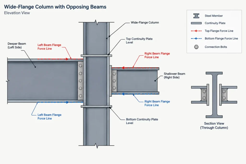
When beams frame into both sides of a column, one continuity-plate pair may appear capable of serving both connections. That conclusion should only be made after checking the actual flange elevations.
Opposite-side beam flanges can be offset because the beams have:
- Different depths
- Different flange thicknesses
- Different top-of-steel elevations
- Different slopes
- Different end rotations or connection configurations
- Camber or erection geometry affecting the represented condition
Equal top-of-steel elevations do not guarantee equal bottom-flange elevations. Likewise, beams of equal nominal depth may not have matching flange geometry. Where flange force lines do not coincide, the engineer may require separate continuity plates, revised plate geometry, or another connection arrangement.
The detailer should flag the offset rather than merging nearby plate levels for drawing convenience.
Fitting the Plate Inside a Rolled Column
A continuity plate fitted between column flanges does not occupy a perfectly rectangular opening. Rolled wide-flange shapes have web-to-flange fillets, and those curved regions reduce the usable space near the flange roots.
The plate detail may therefore need corner clips, shaped cutouts, or another approved clearance treatment. A sharp rectangular plate modeled to the theoretical intersection of the column web and flange can clash with the rolled fillet even when the overall plate width appears correct.
Use Published Shape Geometry Carefully
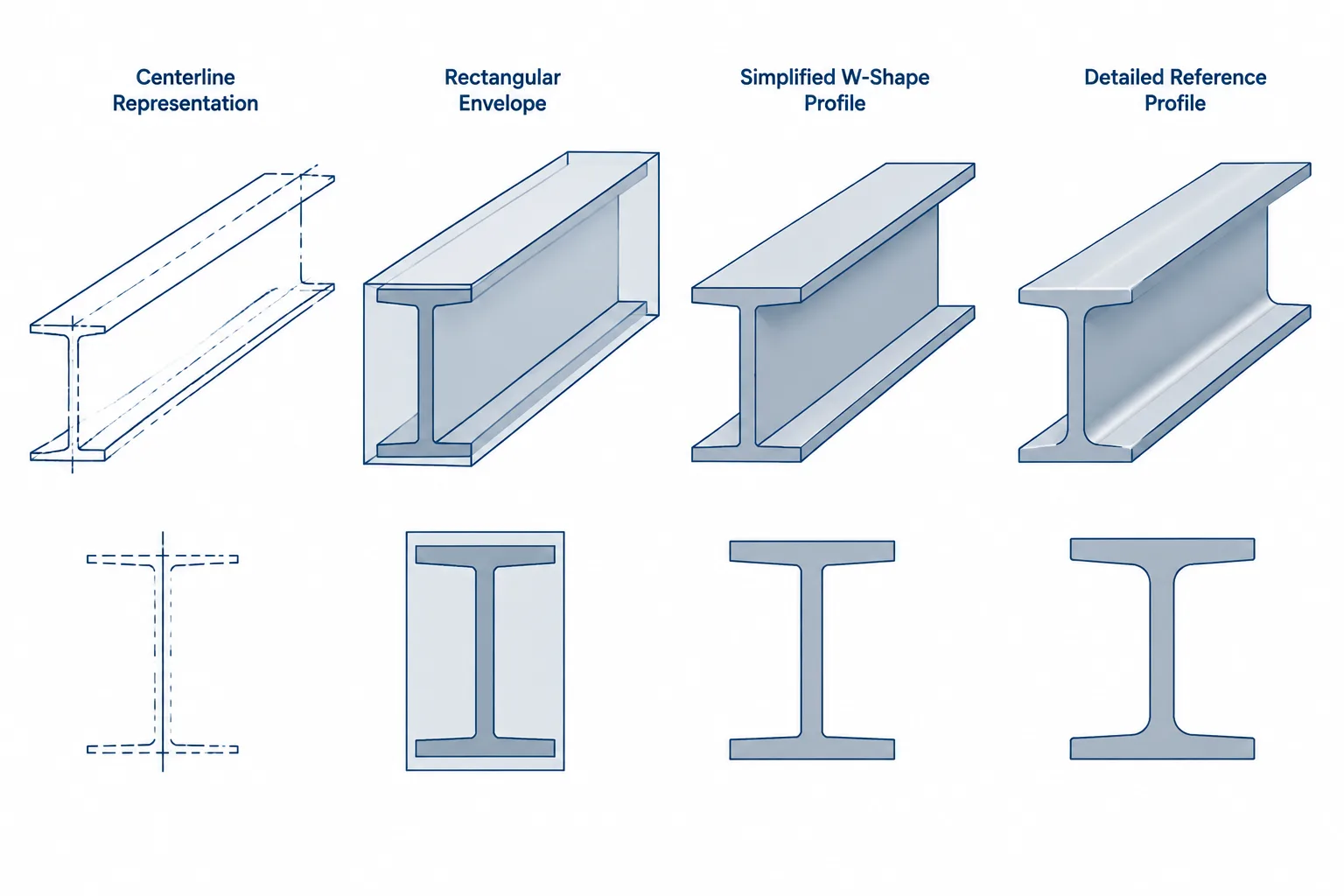
Shape-table dimensions can help define the protected fillet region, but a generic CAD outline should not be treated as fabrication authority. Confirm that the selected shape data, model geometry, and project member designation refer to the same section.
For detailing purposes, distinguish among:
- The nominal cross-section outline used for general arrangement
- The detailing dimensions used to avoid rolled fillets
- The actual fit-up geometry selected by the fabricator
- The engineered net or effective plate dimensions
A clearance cut that solves a physical clash can also reduce the plate area available near an important force path. For that reason, significant clips or copes should not be introduced solely as a drafting fix without engineering review.
Continuity Plates and Doubler Plates
Continuity plates and doubler plates can occur in the same connection zone, but they address different behaviors and create different detailing conditions.
| Item | Typical location | Primary coordination issue |
|---|---|---|
| Continuity plate | Transverse to the column web near a beam-flange level | Flange-force alignment, fit between column flanges, and weld access |
| Doubler plate | Along the column web in the panel-zone region | Plate termination, web attachment, interference, and sequencing |
| Beam connection plate | At the column face or within the beam-end connection | Bolt or weld layout, erection clearance, and load-path coordination |
A doubler plate can alter the surface against which a continuity plate fits. It may also change weld access and the order in which internal components can be installed. A connection should therefore be reviewed as one three-dimensional assembly rather than as unrelated two-dimensional plate details.
Weld Access and Fabrication Sequence
A plate may fit geometrically but still be difficult to fabricate. The detailer should consider how the plate enters the column, where welds can be deposited, and whether adjacent components block access.
Useful coordination questions include:
- Can the plate be inserted between the flanges in the intended sequence?
- Are the plate edges accessible for the specified welds?
- Does a doubler plate block access to the column web?
- Do opposite-side connection components compete for the same space?
- Will the proposed weld sequence create avoidable congestion?
- Are inspection surfaces visible and reachable?
The shop may prefer a particular sequence based on equipment and established procedures. The drawing should define the required finished assembly without assuming an unverified fabrication method. Questions affecting weld type, extent, or structural behavior must be resolved with the responsible engineer.
Sloped Beams Need More Than an Elevation Check
For a sloped beam, the beam flange is not horizontal. A horizontal continuity plate and an inclined beam flange therefore do not share identical geometry across the full connection depth.
The connection design may use a horizontal plate, a plate aligned with the flange, a shaped plate, or another force-transfer detail. The correct solution depends on the engineered connection, not on which option is easiest to draw.
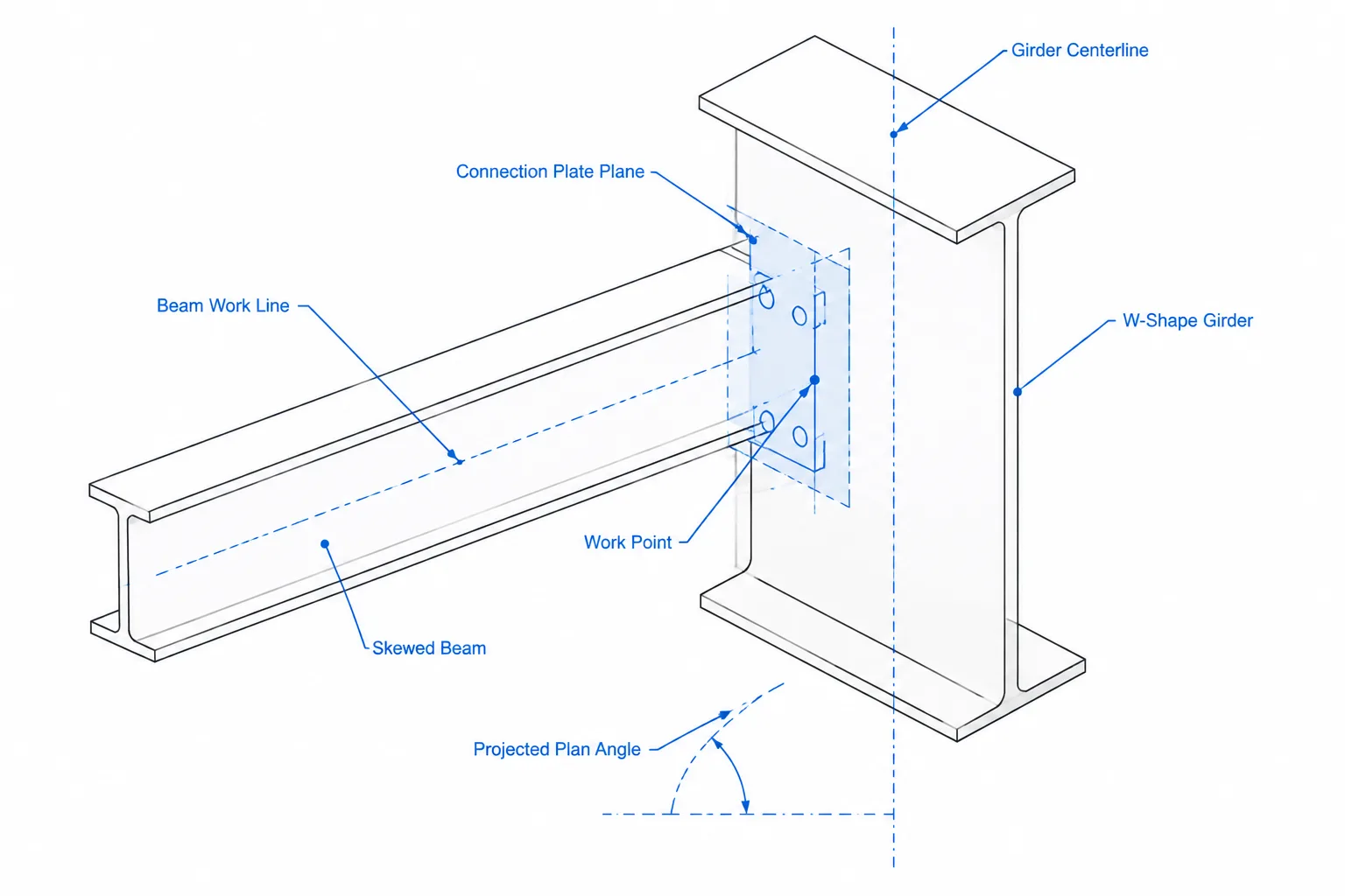
In CAD or BIM, inspect the true three-dimensional intersection at the column face. A projected elevation can hide a mismatch that becomes obvious in a section or model view. Compound slopes and skewed framing deserve particular attention because the visible flange level can vary across the column face.
Recommended Drawing Information
A useful continuity-plate detail generally communicates enough information to locate, fabricate, and verify the part without relying on scale. Depending on the project, that information may include:
- Plate mark and material designation
- Plate thickness and cut dimensions
- Elevation or datum controlling each plate level
- Relationship to the corresponding beam flange
- Corner clips, tapers, or fit clearances
- Weld symbols and limits established by the connection design
- Relationship to doubler plates and other internal components
- Near-side, far-side, or both-side identification where views could be ambiguous
Sections through the column are especially useful. An elevation can establish vertical position, while a section can show whether the plate spans between flanges, fits to a doubler plate, or uses divided components on opposite sides of the web.
A Practical CAD and Model Review Workflow
- Confirm member identity. Verify the beam and column shapes against the current design documents.
- Establish datums. Identify the controlling top-of-steel, work-point, or flange reference elevations.
- Calculate actual flange locations. Use verified section geometry rather than nominal depth labels alone.
- Compare opposite framing. Check each beam independently before assuming shared plate levels.
- Model the column interior. Include sufficient fillet or keep-out geometry to identify fit conflicts.
- Add all connection-zone parts. Review doubler plates, web plates, flange plates, bolts, weld-access regions, and nearby stiffeners together.
- Inspect sections and 3D views. Do not rely only on the primary elevation.
- Review fabrication access. Consider insertion, welding, inspection, and sequencing.
- Record unresolved conditions. Send alignment, fit, and design questions through the project’s formal coordination process.
Common Detailing Errors
- Locating plates from nominal beam depth without checking flange thickness
- Assuming beams with matching top elevations have matching bottom flanges
- Ignoring column web-to-flange fillets
- Modeling continuity and doubler plates independently even though they intersect
- Copying a connection from one side of a column to the other without checking member geometry
- Using a simplified section outline for final fit-up decisions
- Adding large corner clips to clear a clash without engineering review
- Showing plate geometry but omitting a reliable vertical locating dimension
Final Coordination Principle
A continuity plate is a small component within a concentrated and often congested force-transfer zone. Good detailing begins with the beam-flange load path, then accounts for real rolled-shape geometry, adjoining reinforcement, weld access, and fabrication sequence.
Whenever beam size, elevation, slope, column orientation, or panel-zone reinforcement changes, continuity-plate geometry should be reviewed again. Treating the connection as a coordinated three-dimensional assembly is more reliable than positioning each plate from an isolated typical detail.