The words compact, noncompact, and slender describe how the plate-like elements of a steel cross-section may behave under compression. They do not simply indicate whether a shape looks heavy or thin, and they are not interchangeable with overall member slenderness.
This distinction matters when selecting sections, reviewing calculations, building CAD models, and evaluating substitutions. Two shapes with similar depth and weight can have different local-buckling behavior because their flange widths, web depths, thicknesses, support conditions, and stress patterns differ.
Local buckling begins within the cross-section
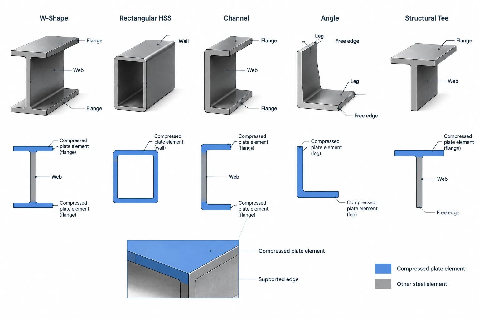
A rolled or built-up steel section can be viewed as an assembly of plate elements. The flanges and web of a W-shape, the legs of an angle, and the walls of an HSS each have a width or depth measured relative to their thickness. When one of these elements is compressed, a relatively thin region may buckle locally before the entire member reaches another strength limit.
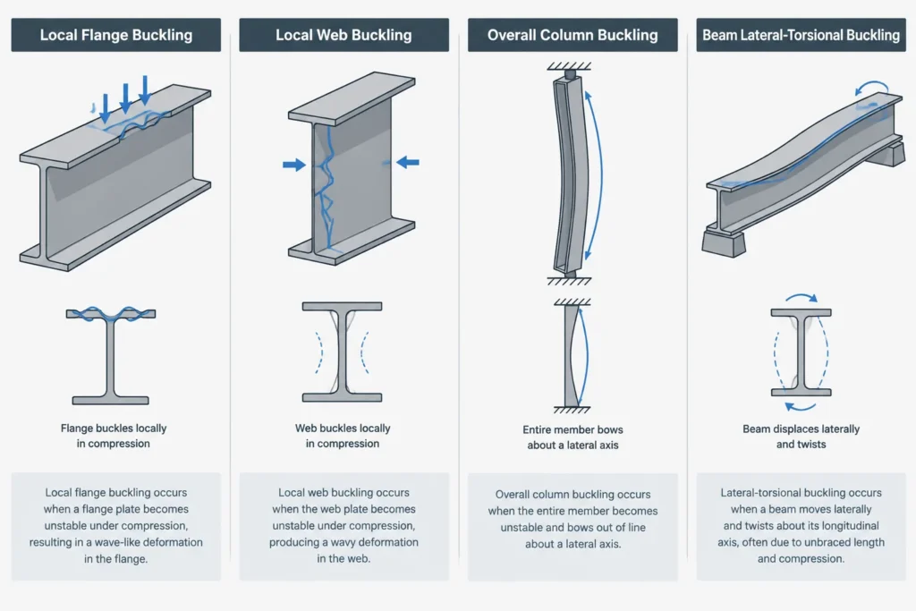
Local buckling is different from a column bowing over its full unbraced length or a beam undergoing lateral-torsional buckling. It is a localized distortion of a flange, web, leg, or wall. The relevant width-to-thickness ratio is commonly written in the general form b/t, although the definition of b depends on the element and the applicable design provisions.
What compact, noncompact, and slender mean
For flexural behavior, steel elements are commonly grouped according to whether local buckling is expected before or after important stages of cross-sectional yielding.
| Classification | General behavior | Practical implication |
|---|---|---|
| Compact | The compression elements can generally develop substantial yielding before local buckling limits the section. | The section may be able to develop its plastic flexural strength when other requirements are also satisfied. |
| Noncompact | Local buckling may occur after yielding begins but before the section develops its full plastic flexural strength. | Flexural strength is typically reduced from the plastic result according to the applicable design method. |
| Slender | A compression element may buckle locally before yielding spreads through the relevant part of the section. | Local-buckling reductions or effective-section concepts may govern the calculated strength. |
These descriptions concern cross-sectional behavior only. A compact beam section can still be controlled by lateral-torsional buckling, connection strength, deflection, vibration, or another limit state. Similarly, a section containing a slender element is not automatically unusable; it requires the appropriate design treatment.
Classify elements before classifying the section
A section is not evaluated from one universal width-to-thickness ratio. Its individual compression elements must be identified and checked using the definitions appropriate to their geometry, edge support, loading, and stress distribution.
W-shape flanges
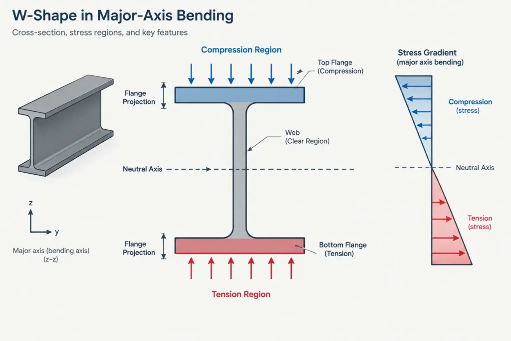
Each half of a W-shape flange projects from the web and has one supported longitudinal edge and one free edge. It therefore behaves as an unstiffened compression element. Its ratio is based on the flange projection relative to flange thickness, using the dimensional definition prescribed by the governing design method.
A wide flange is not necessarily slender. A thicker flange may have a lower width-to-thickness ratio than a narrower but much thinner flange. Visual appearance alone is unreliable.
W-shape webs
The web is supported along both longitudinal edges by the flanges, so it is treated differently from a projecting flange. Its clear depth and web thickness are central to the check, but the exact clear-depth definition must come from the applicable provisions rather than from an arbitrary CAD measurement.
Web classification also depends on the stress condition. A web in flexure has a stress gradient: one region may be in compression while another is in tension. A web under nearly uniform axial compression has a different condition. The same physical section can therefore require different classification checks for different loading cases.
HSS walls
The walls of square and rectangular HSS are generally supported by adjacent walls, but the curved corner regions affect how the flat width is defined. The overall outside width divided by nominal wall thickness is not automatically the ratio used in a design check.
The designer must distinguish among outside dimensions, flat-wall dimensions, nominal wall thickness, and any thickness used by the governing calculation method. A simplified sharp-corner CAD rectangle should not be treated as a substitute for the prescribed geometric definitions.
Round HSS uses diameter-to-thickness behavior rather than a flat-plate width-to-thickness ratio. It therefore follows different local-buckling relationships from rectangular HSS.
Angles, channels, and tees
Angle legs, channel flanges, and tee stems may include projecting compression elements with free edges. Their support conditions and stress distributions differ from those of a W-shape web or closed HSS wall. Unsymmetrical shapes can also place compression in unexpected regions when bending occurs about a principal axis or under combined loading.
Do not transfer a ratio definition from one shape family to another merely because both elements are called flanges or legs.
Element classification can change with the load case
Classification is not always a permanent label attached to a database entry. The same shape may be considered under axial compression, major-axis bending, minor-axis bending, or combined forces. Those cases can produce different compressed elements and different stress patterns.
- In major-axis bending of a typical W-shape, one flange is primarily in compression and the web has a stress gradient.
- In axial compression, both flanges and the web are compression elements.
- In minor-axis bending, the distribution of compression across the flanges differs from major-axis bending.
- In an angle or tee, the orientation of the load relative to the principal axes can materially affect which portions are compressed.
Material strength also matters because classification limits are tied to the relationship between elastic stiffness and yielding. Consequently, the same geometry should not be assumed to retain the same classification when a different specified material strength is introduced.
Local slenderness is not KL/r
One of the most common terminology errors is calling a member slender without stating whether the subject is local or global behavior.
| Concept | Typical ratio | What it describes |
|---|---|---|
| Element slenderness | b/t or a related diameter-to-thickness ratio | Local buckling of a flange, web, leg, stem, or HSS wall |
| Member slenderness | KL/r | Overall column buckling over an effective member length |
| Beam stability | Uses unbraced-length and section parameters | Lateral movement and twist of a flexural member |
A column can have a low overall slenderness ratio while containing a slender plate element. Conversely, a section with nonslender elements can still form a globally slender column because of its length, end conditions, or weak-axis radius of gyration. Both checks may be necessary.
What shape tables and CAD geometry can—and cannot—tell you
Shape tables provide the dimensions and section properties needed to begin a classification check, but the table entry alone may not state the classification for every possible load case and material. Published dimensions also follow specific conventions that may differ from values measured from a simplified CAD outline.
A CAD model is useful for identifying the topology of the section: free edges, supported edges, wall arrangement, and member orientation. It can also help organize extracted dimensions. However, automatic measurements can be misleading when a model:
- uses sharp corners instead of rolled fillets or formed HSS corners;
- measures an overall width where a clear or flat width is required;
- uses an idealized wall thickness without documenting its source;
- contains a scaled block rather than verified section geometry;
- assigns the wrong material or member orientation; or
- treats a built-up member as though it were a standard rolled shape.
For design checks, obtain geometry and properties from an appropriate verified source, then apply the definitions in the governing design criteria.
A practical review workflow
- Confirm the section and material. Verify the exact shape designation, built-up geometry, and specified material information.
- Define the load case. Identify axial force, bending axes, stress gradient, and any combined loading relevant to the check.
- Identify compression elements. Mark each flange projection, web, angle leg, tee stem, or HSS wall that can carry compression.
- Determine edge support. Distinguish elements supported along both longitudinal edges from elements with a free edge.
- Use the correct width definition. Do not substitute overall CAD dimensions for clear, flat, or projecting widths without verification.
- Calculate the applicable ratios. Keep the ratios for separate elements clearly labeled rather than reporting one generic section ratio.
- Compare with the governing limits. Use the project’s adopted design standard and the correct provisions for the member type, force condition, and material.
- Carry the result into strength checks. Classification is an input to design calculations, not a final statement of capacity.
Why this matters during shape substitution
Replacing a member with a shape of similar depth, weight, area, or moment of inertia does not guarantee equivalent local-buckling behavior. The replacement may have thinner flanges, a deeper clear web, different HSS wall proportions, or a different element support condition.
A responsible substitution review should therefore recheck element classification alongside strength, stability, deflection, connection geometry, clearances, and fabrication requirements. Compact, noncompact, and slender are behavioral classifications—not visual descriptions or simple indicators of section size.


