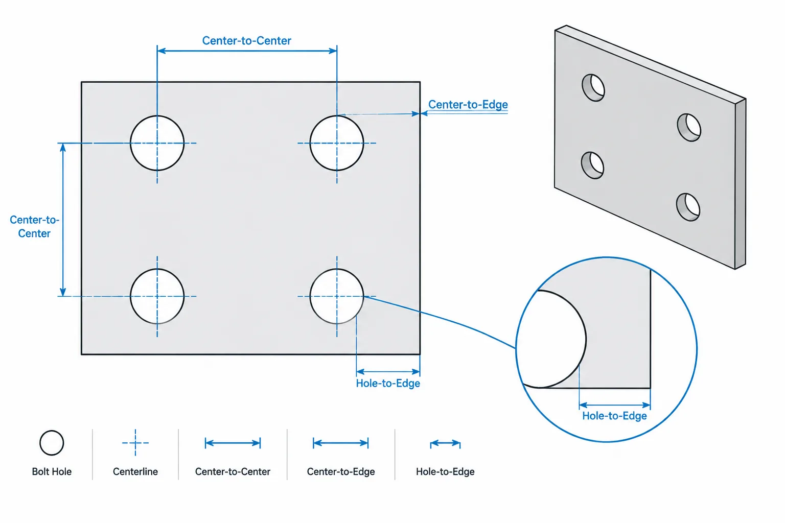
A bolt hole can appear safely inside a steel plate while still being dimensioned incorrectly. The confusion often comes from treating bolt hole edge distance and the clear material between the hole and plate edge as the same measurement. They are related, but they are not interchangeable.
For most structural-steel detailing, edge distance is located from the center of the hole to an adjacent material edge. Clear distance, sometimes described informally as edge clearance or the remaining ligament, is measured from the hole boundary to that edge. This distinction affects drawing interpretation, connection checks, CNC data, slotted holes, skewed plates, and revisions that change either the hole size or plate outline.
What Is Bolt Hole Edge Distance?
Bolt hole edge distance is generally the distance from a hole center to the relevant edge of the connected part. On a rectangular plate, this may be shown from a bolt line to the side edge or from the first hole in a row to the plate end.
The hole center is the stable layout point. A fabricator can use that coordinate to locate a drill, punch, or cutting operation regardless of how the hole is produced. It also fits naturally into baseline and ordinate dimensioning systems.
Depending on the connection and drawing convention, the following terms may appear:
- Edge distance: commonly used for the center-to-edge distance measured across the width of a plate or member.
- End distance: commonly used for the center-to-end distance along the member or connection direction.
- Hole-center coordinate: a neutral geometric description that avoids ambiguity about whether an edge is considered a side or an end.
The distinction between an edge and an end can be useful, but it should not be assumed solely from sheet orientation. A plate may be rotated in an assembly, and the controlling connection direction may not match the horizontal or vertical direction on the detail.
What Is Clear Distance to the Edge?
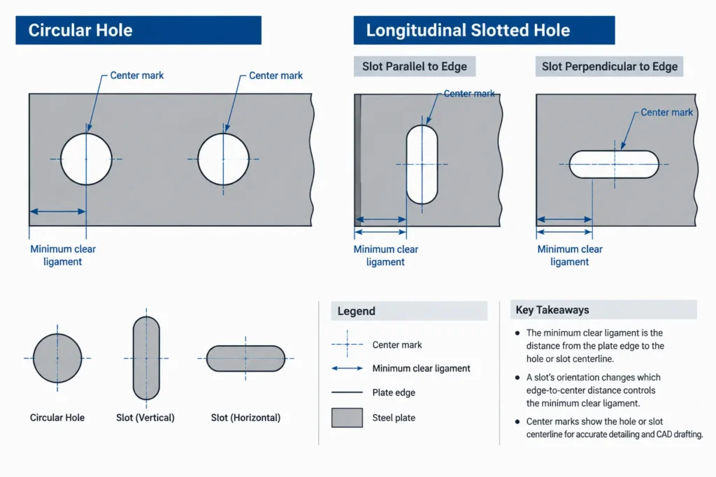
Clear distance is the shortest remaining material between the hole boundary and the plate edge. For a circular hole next to a straight edge, the basic geometric relationship is:
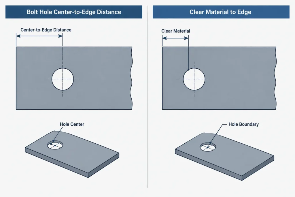
clear distance = center-to-edge distance − hole radius
This relationship applies when the center-to-edge dimension is measured perpendicular to the straight edge. If the edge is skewed, curved, notched, or interrupted by another cut, a simple horizontal or vertical subtraction may not represent the actual minimum ligament.
Clear distance is useful for understanding physical fit and remaining material. However, it should not be substituted automatically for a required edge-distance criterion. Structural requirements are commonly written around specified hole-center distances, hole types, edge conditions, loading, and other design variables. The governing project documents and connection design must establish the required values.
Why the Difference Matters
A hole-center dimension can remain unchanged while the clear material changes. This happens when a standard circular hole is revised to a larger hole or slot without moving its center. Conversely, a plate edge can be trimmed while the bolt pattern remains fixed, reducing both the center-to-edge distance and the clear ligament.
| Change | Hole-center edge distance | Clear material to edge |
|---|---|---|
| Hole diameter increases about the same center | Unchanged | Decreases |
| Plate edge moves toward the hole | Decreases | Decreases |
| Hole center moves inward | Increases | Usually increases |
| Circular hole becomes a slot | Center may remain unchanged | Depends on slot direction and geometry |
This is why checking only the bolt-line dimension is not enough after every revision. A change to hole geometry or plate geometry may create a new minimum clearance condition even when the coordinate list has not changed.
Measuring to Straight and Skewed Plate Edges
Straight, parallel edges
For a rectangular plate with bolt rows parallel to its sides, edge-distance checks are straightforward. Measure from each relevant hole center perpendicular to the adjacent plate edge. Baseline dimensions can locate the bolt line from a stable plate datum.
Skewed edges
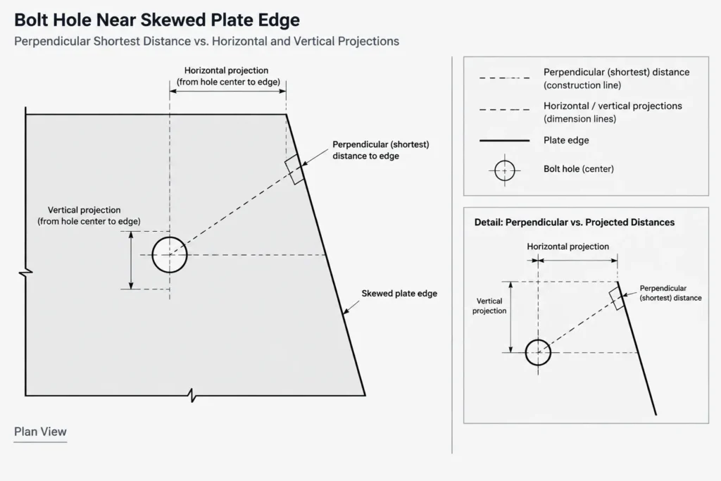
For a skewed edge, the shortest center-to-edge distance is measured along a line normal to that edge. A horizontal or vertical dimension may be only a projection and can overstate the true distance.
In CAD, use perpendicular constraints, nearest-point measurements, or construction geometry normal to the cut edge. Do not rely on visual spacing in an oblique view. When a plate has more than one angled boundary, check the nearest relevant edge rather than assuming the nominal side edge controls.
Curved cuts and notches
A curved cut can create a minimum distance that does not align with either model axis. The useful check is the shortest distance from the hole center or hole boundary to the actual cut profile. Notches, cope transitions, relief cuts, and clipped corners should be included in the geometry used for this check.
Slotted Holes Require Directional Checks
A slotted hole has a center point, but its boundary extends farther in one direction than a circular hole. As a result, a center-to-edge dimension alone may not reveal the minimum clear material.
Slot orientation should be explicit on the drawing or unambiguous from the modeled geometry. A slot directed toward a nearby plate edge produces a different remaining ligament than the same slot rotated parallel to that edge. The check should consider:
- the slot center location;
- the slot longitudinal axis;
- the complete slot boundary, including end arcs;
- the nearest plate edge, corner, cope, or cutout;
- the permitted direction of connection movement, where applicable; and
- the hole type specified by the connection design.
Do not infer slot direction from a generic oblong symbol if the drawing view, dimensioning, or note leaves room for interpretation.
Plate Corners Can Be the Controlling Boundary
A hole near two edges must be checked against both. Near a square corner, separate perpendicular edge distances may describe the layout adequately. Near a clipped, chamfered, or radiused corner, the closest point may lie on the corner treatment rather than on either original plate edge.
This issue often appears when a standard rectangular connection plate is revised for access, drainage, architectural clearance, or interference avoidance. The bolt coordinates may remain untouched while a new diagonal cut moves the material boundary closer to one hole.
A reliable revision review therefore compares the entire hole boundary with the final plate perimeter, not merely the original width and length dimensions.
A Practical CAD Checking Workflow
- Confirm the controlling geometry. Identify the final plate perimeter, including clips, notches, radii, copes, and skewed cuts.
- Confirm hole definitions. Distinguish circular holes from slots and verify the modeled hole size and orientation against the connection information.
- Locate holes from stable datums. Use plate edges, centerlines, work points, or approved connection datums rather than chaining every hole from the previous one.
- Measure center-to-edge distances. Check perpendicular distances to straight edges and shortest distances to irregular boundaries.
- Check clear geometry separately. Measure from the actual hole or slot boundary to the final plate outline where tight conditions exist.
- Review both sides of multi-ply connections. A hole may have adequate spacing in one ply but lie near an edge, cope, or member fillet in another.
- Recheck after revisions. Changes to plate size, bolt count, hole type, slot direction, or member setback can alter the controlling condition.
Automated clearance circles or offset regions can help flag close conditions, but they should be treated as checking aids. Their radius or offset must come from verified project criteria, and they may not capture every directional or edge-condition requirement.
Dimensioning Practices That Reduce Ambiguity
Shop drawings should make hole location reproducible without forcing the fabricator to scale the view. Helpful practices include:
- dimensioning hole centers rather than hole boundaries;
- using center marks and centerlines consistently;
- identifying slot size and direction through verified project conventions;
- locating bolt rows from a clear datum;
- showing skewed edges with enough geometry to establish their true position;
- avoiding duplicate dimensions that can conflict after revisions; and
- distinguishing informational clearances from controlling fabrication dimensions.
If a detail labels a dimension as clear, verify exactly which two boundaries it references. “Clear to edge” could describe the gap from a hole, washer, bolt head, weld, or adjacent part. A precise note or dimension extension line is more reliable than shorthand alone.
Do Not Confuse Edge Distance with Tool or Hardware Clearance
Adequate bolt hole edge distance does not automatically provide room for every operation around the bolt. Washer fit, bolt-head rotation, wrench access, welding access, and interference with adjacent flanges or stiffeners are separate coordination checks.
Likewise, a washer fitting within the plate outline does not prove that the structural hole edge distance is acceptable. One check concerns physical occupancy; the other concerns the designed and specified connection geometry.
Key Takeaway
Bolt hole edge distance is primarily a hole-center-to-material-edge measurement. Clear distance describes the material remaining from the hole boundary to the edge. On simple circular holes beside straight edges, the two are easily related. With slots, skewed cuts, clipped corners, and irregular plate profiles, the actual minimum distance must be checked using the complete geometry.
Detailers should show reproducible hole-center locations, model the final plate perimeter accurately, and treat clear-ligament checks as a separate review step. Required minimums must come from the connection design, applicable project criteria, and governing requirements—not from a generic CAD block or visual judgment.