A steel angle bolt gage defines the transverse location of a bolt-hole line on an angle leg. Although the concept appears simple, the dimension can become ambiguous when drawings do not identify the connected leg, the reference datum, or the angle orientation. Unequal-leg angles, double-angle assemblies, staggered holes, and mirrored details add further opportunities for error.
Published shape information may include commonly used or workable gages, but a listed gage is not a complete connection layout. The detailer must still coordinate hole locations with the selected angle, connected material, fastener hardware, rolled fillet, free toe, welds, and project-specific connection requirements.
What Is Bolt Gage on a Steel Angle?
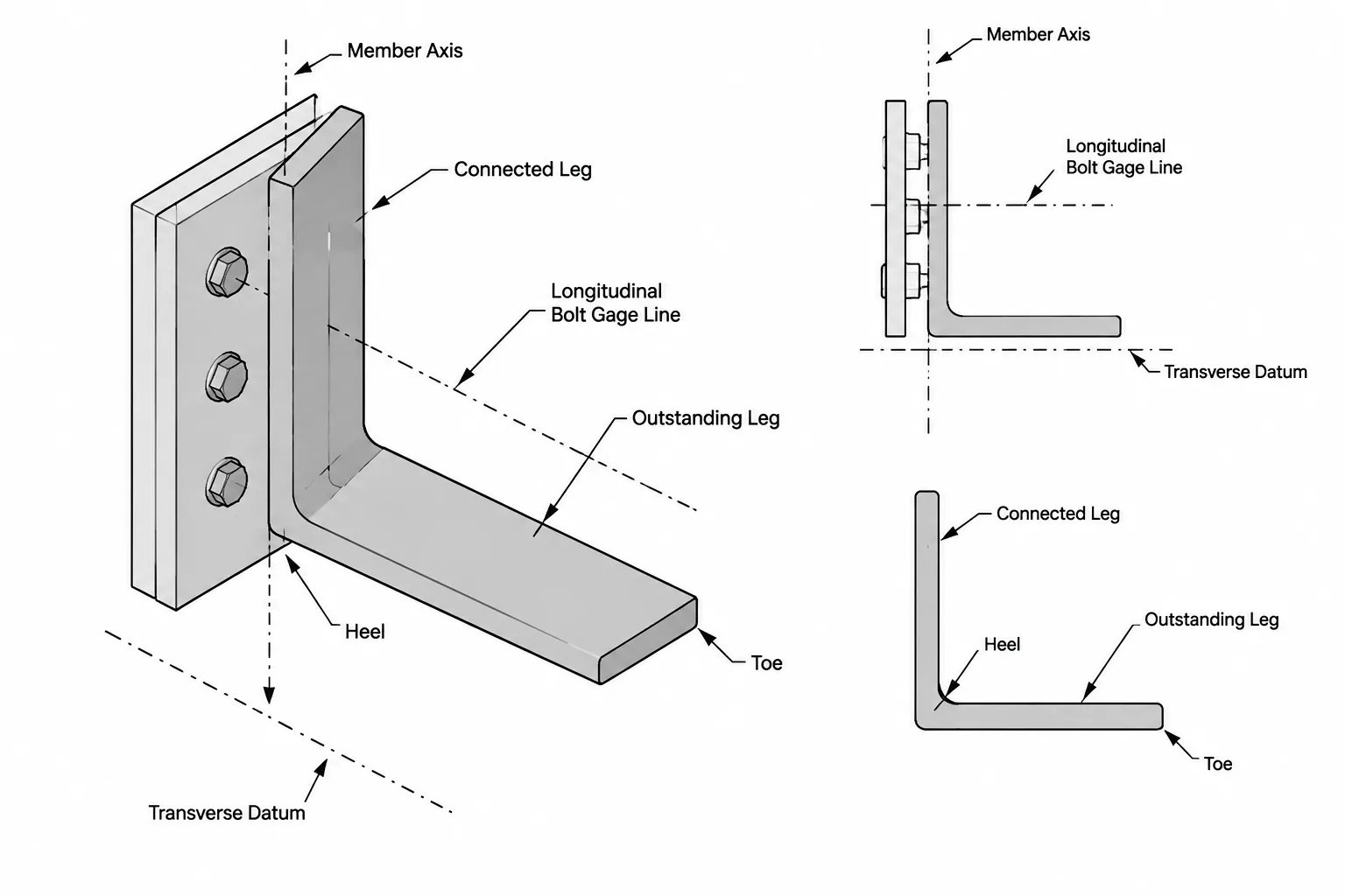
In angle detailing, a bolt gage is generally the transverse distance used to locate a longitudinal line of holes on a leg. The bolt line normally runs parallel to the member axis, while the gage dimension runs across the angle leg.
This differs from several other dimensions in the connection:
- Pitch is the center-to-center spacing between holes along a bolt line.
- End distance locates a hole center relative to the end of the angle.
- Edge distance relates a hole center to a material edge, such as the free toe of the angle.
- Gage locates one bolt line across the leg or defines the spacing between multiple bolt lines.
A drawing should not use the word “gage” as a substitute for every transverse hole dimension. The controlling datum and direction must remain clear.
The Datum Matters More Than the Label
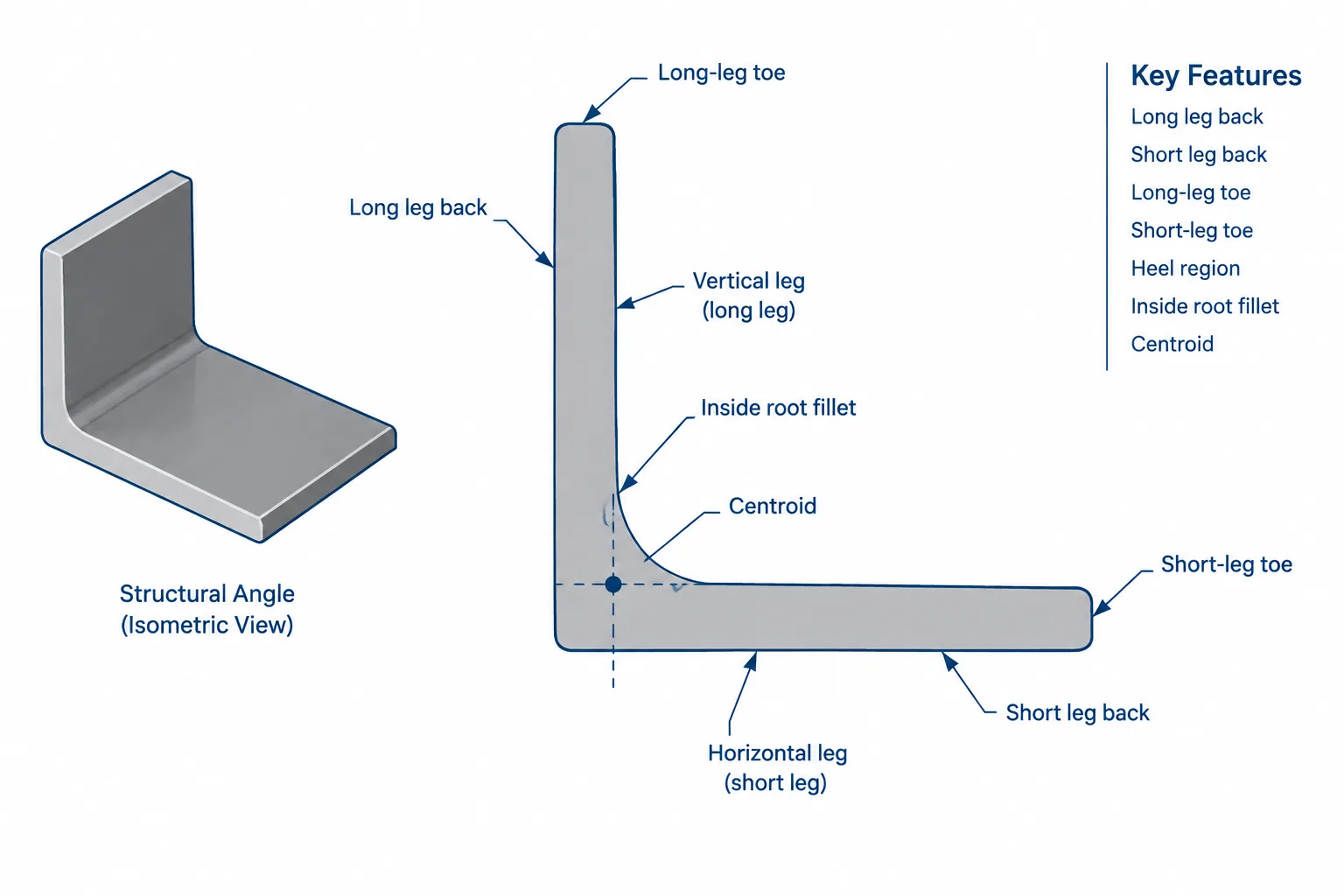
Angle geometry includes two legs, two free toes, a heel region, a rolled inside fillet, and rounded toe transitions. Because the physical inside corner is not sharp, it is generally unsuitable as a direct shop measurement surface.
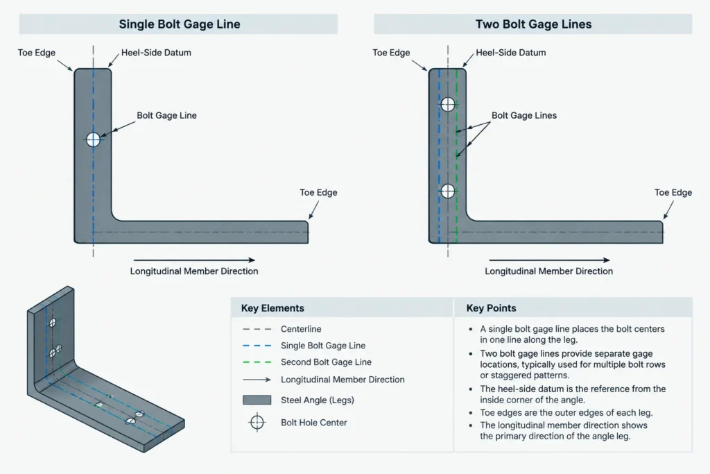
Industry references often express an angle gage from a heel-side or back-of-angle datum. However, terminology and drafting conventions can vary. A detail should make the intended datum visible rather than relying on the reader to infer it from a table or office custom.
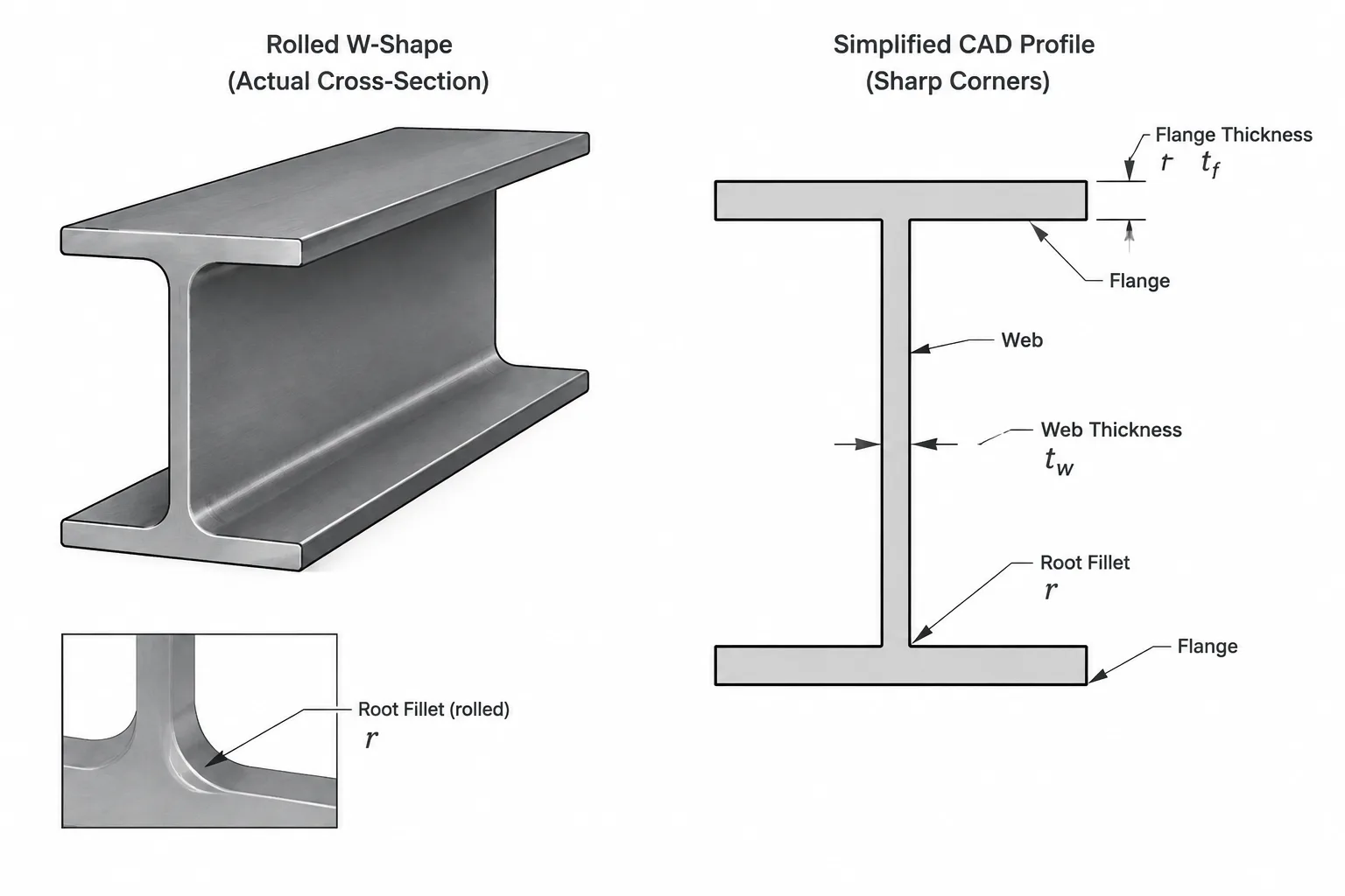
In CAD, a theoretical intersection of leg reference lines can be useful as a construction datum. That theoretical point is not the same as the tangent point or surface of the rolled root radius. If a model uses simplified sharp-corner geometry, the detailer should ensure that the resulting hole coordinate still corresponds to a practical fabrication datum.
Useful Angle Hole-Layout Terms
| Term | Practical meaning | Common detailing concern |
|---|---|---|
| Heel | The corner region where the two angle legs meet | The rolled fillet occupies space near this region |
| Toe | The free edge of an angle leg | Hole placement must maintain the required edge relationship |
| Connected leg | The leg attached to a plate, web, flange, or other member | Its orientation determines which gage controls the connection |
| Outstanding leg | The leg projecting away from the connected surface | May require clearance for framing, welding, or adjacent parts |
| Gage line | A longitudinal line passing through hole centers | Must be located from an unambiguous transverse datum |
| Two-line gage | A layout with two longitudinal hole lines on one leg | Requires both overall placement and spacing to be defined |
Connected-Leg Orientation Controls the Layout
An angle designation alone does not establish which leg is bolted. For an unequal-leg angle, connecting the long leg produces a different available width and bolt-line position than connecting the short leg. Even for an equal-leg angle, rotating or mirroring the member can change drawing interpretation, access, and the relationship to adjacent material.
The drawing or model should establish:
- Which leg is connected and which leg is outstanding.
- Whether the angle is viewed from the near side or far side.
- The direction of the member from its start end to its end end.
- The face against the supporting plate or member.
- The datum used for the transverse hole coordinate.
These items are especially important when the assembly is handed. A mirrored angle is not automatically interchangeable with the original part when holes, clips, welds, or end cuts are asymmetric.
Single and Multiple Gage Lines
A narrow connected leg may use one longitudinal bolt line, while a wider leg may permit multiple lines. The appropriate arrangement is a connection-design decision, not something that should be selected solely because a shape table displays a familiar gage.
For one bolt line, the detail should locate the line from a stated datum and allow the toe-side edge relationship to be checked. For two bolt lines, the drawing may use a datum-to-first-line dimension plus spacing between lines, or another clearly defined baseline arrangement. The dimension scheme should allow the shop to reproduce the layout without accumulating unnecessary chain-dimension error.
When holes are staggered, separate the two concepts visually: the gage establishes the transverse bolt lines, while the longitudinal coordinates establish the stagger. A diagonal center-to-center dimension by itself can hide both controlling components and complicate CNC verification.
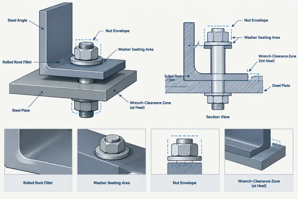
Rolled Fillets and Fastener Clearance
A hole center that appears to fit within the nominal leg width may still place the bolt head, nut, or washer too close to the angle fillet. The hole is only one part of the required envelope. Installation tools and the geometry of connected plies may create additional constraints.
Checks near the heel should consider:
- The actual rolled fillet zone for the selected angle.
- The outside dimensions of the specified fastener components.
- Washer seating on a sufficiently flat surface.
- Nut rotation and tightening-tool access.
- Possible interference with welds or adjacent plates.
- Whether the CAD profile is exact enough for the clearance review.
A simplified angle block with a sharp inside corner can conceal a real clash. For connection-level modeling, use verified shape geometry or add an explicit keep-out region representing the fillet and required installation space.
Toe-Side Checks and Edge Relationships
Locating a hole line from the heel side does not eliminate the need to check the free toe. The remaining distance from the hole center to the toe depends on the actual leg width and the selected gage. Hole type, loading direction, fabrication method, and governing design criteria can affect what is acceptable.
A drafter should therefore avoid treating a commonly used gage as proof that every edge condition is satisfactory. If the shape changes, even within a related family, recalculate or reverify the toe-side relationship rather than copying the previous connection unchanged.
Double-Angle Assemblies
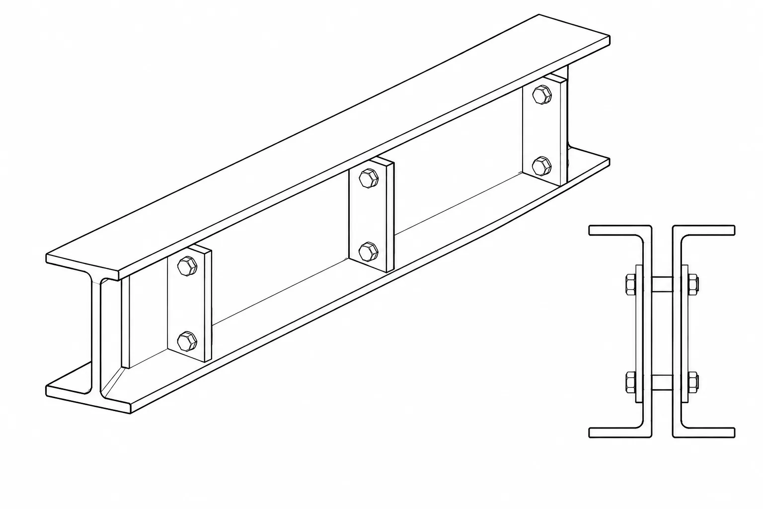
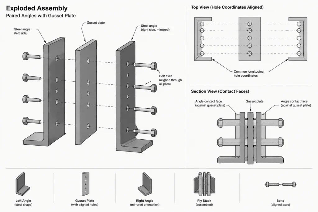
Double-angle connections require careful control of orientation and hole alignment. Angles placed on opposite sides of a gusset or web are often mirror-related, but the fabrication parts may not be identical if other features are handed.
For reliable coordination, use a common longitudinal origin for both angles and the connected plate. Verify that corresponding hole centers align through the complete ply stack. In the transverse direction, establish each angle from its actual contact face rather than assuming that mirrored CAD geometry automatically preserves the intended gage.
If the angles are separated by a gap or intermediate material, model that thickness explicitly. The assembly centerline, angle backs, and connected-plate faces are different datums and should not be used interchangeably.
A Practical CAD and Shop-Drawing Workflow
- Confirm the exact shape. Verify the angle designation, leg sizes, thickness, and orientation against the controlling project information.
- Establish the member axis. Set a consistent longitudinal origin and member direction before laying out holes.
- Identify the connected leg. Do not rely on the designation order or a generic block orientation.
- Select a physical transverse datum. Use a clear back, face, edge, or defined construction line that can be understood on the drawing.
- Lay out gage lines. Keep transverse gage dimensions separate from longitudinal pitch and end dimensions.
- Check the heel zone. Review fillet, washer, fastener, and tool-clearance envelopes.
- Check the toe relationship. Confirm the resulting edge condition using the actual leg width and hole geometry.
- Coordinate mating parts. Compare hole coordinates through every connected ply rather than checking parts in isolation.
- Review handedness. Test mirrored and opposite-end conditions before reusing the part mark.
- Document the source. Record where the selected gage and shape geometry came from so later revisions can be verified.
Final Detailing Checklist
- Is the connected angle leg unmistakable?
- Is the gage datum shown rather than merely implied?
- Are gage, pitch, end distance, and edge relationship treated as separate concepts?
- Has the rolled fillet been included in the clearance review?
- Can the bolt head, nut, washer, and installation tool fit?
- Do holes align through all connected materials?
- Are unequal-leg and mirrored-angle conditions handled correctly?
- Will a shape substitution require the hole layout to be rechecked?
- Do the model, part drawing, assembly drawing, and CNC data use the same origin and orientation?
A dependable steel angle bolt gage is not simply a value copied from a reference table. It is part of a coordinated hole-layout system tied to a specific angle, connected leg, datum, and assembly orientation. Making those relationships explicit produces drawings that are easier to check, fabricate, and revise.