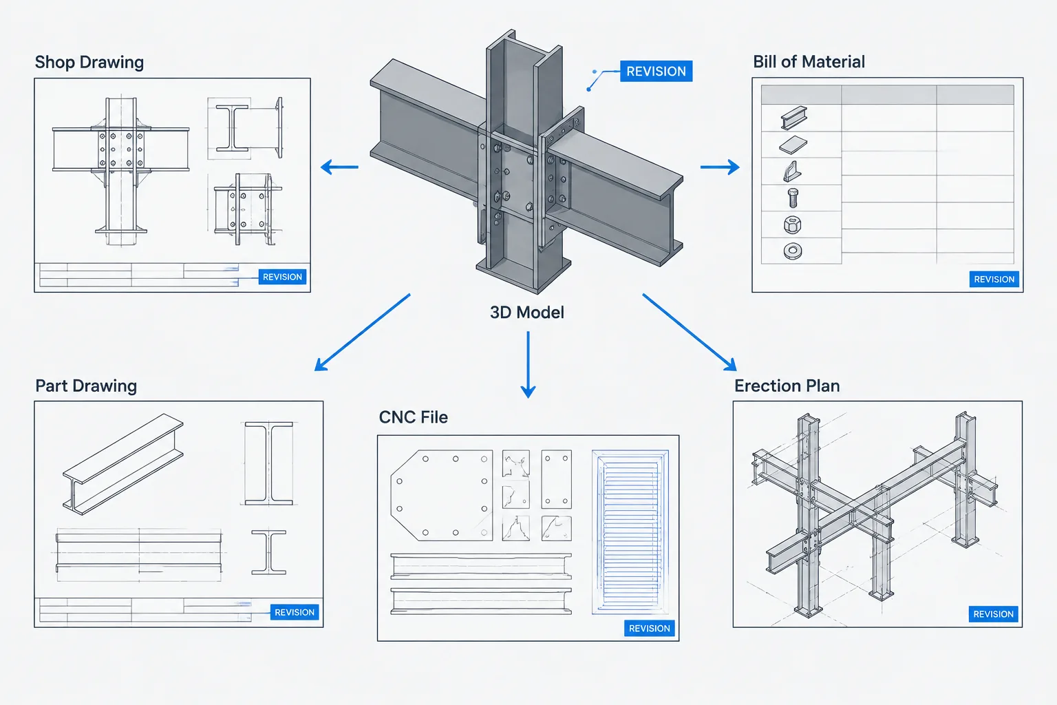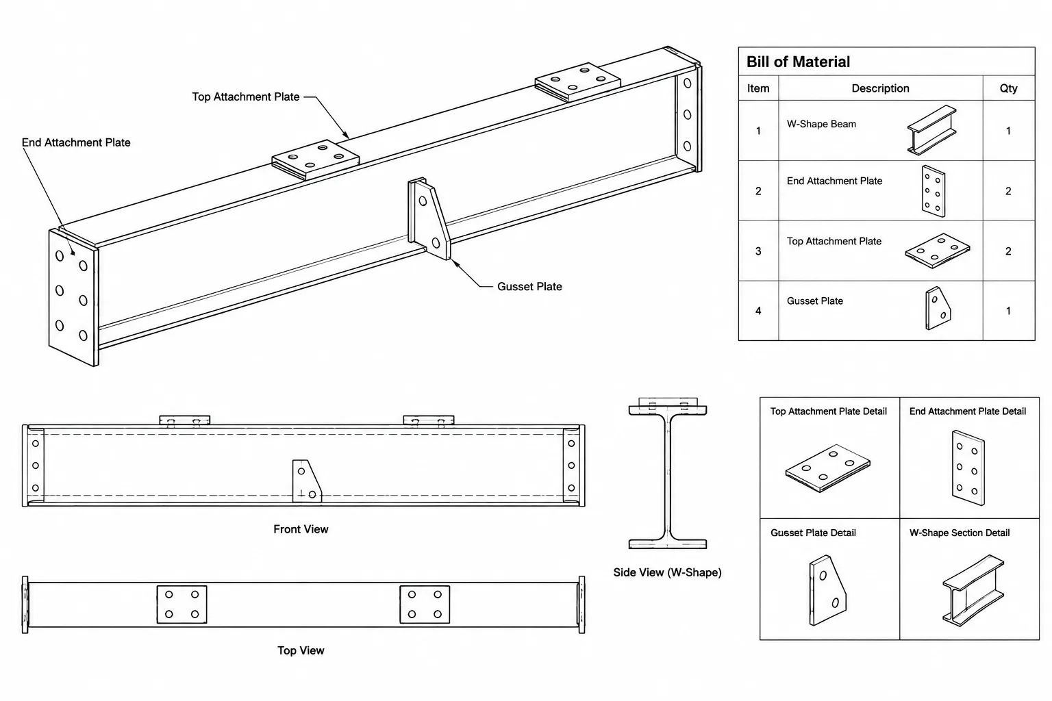
A steel member in a CAD or BIM model is usually positioned from a reference line rather than from every visible face of the shape. The relationship between that line and the section geometry is controlled by an insertion point, justification setting, cardinal point, or similar placement rule.
This setting can appear harmless when a member is first modeled. Its importance becomes clearer when a beam changes depth, an HSS column changes width, or a channel is rotated. Depending on the insertion rule, a shape change may preserve the member centerline, top surface, bottom surface, web back, or another reference. The wrong rule can move connection faces, alter clearances, and invalidate dimensions even though the member endpoints remain unchanged.
Software terminology and cardinal-point numbering are not universal. Drafters should verify each platform’s placement diagram instead of assuming that a familiar number or label has the same meaning in another application.
What Is a Steel Member Insertion Point?
The insertion point is the location within or relative to the cross section that the member’s placement line follows. For a prismatic member, the software sweeps the selected steel shape along that line while maintaining the chosen section orientation.
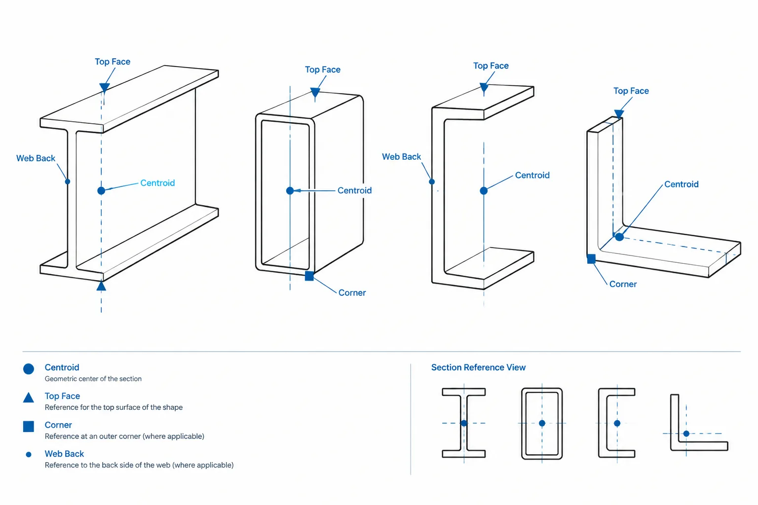
Common reference locations include:
- The section centroid or geometric center
- The top, center, or bottom of the section
- The left or right side of the section
- A flange corner, web centerline, or face of steel
- A user-defined location created with offsets
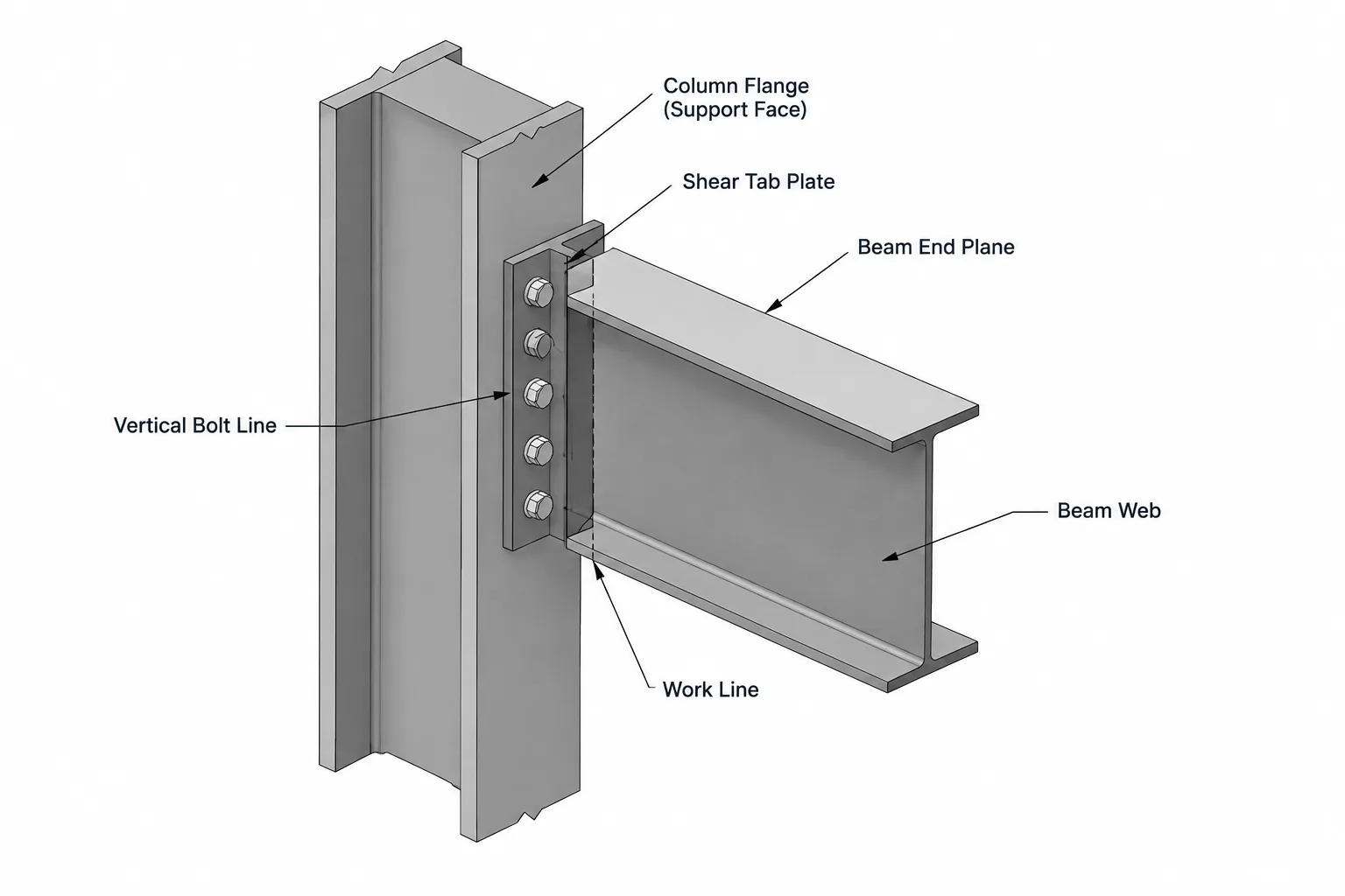
The placement line is not automatically the same as the structural work line, analytical line, centroidal axis, grid line, or dimension datum. Those references can coincide, but they represent different ideas and should be identified separately.
Cardinal Points Are Section-Placement Rules
Many modeling systems organize common insertion locations as a grid of cardinal points around the section. A typical interface may offer combinations such as top-left, top-center, top-right, middle-left, center, middle-right, bottom-left, bottom-center, and bottom-right. Other systems use descriptive justifications, section-specific references, or a different numbering sequence.
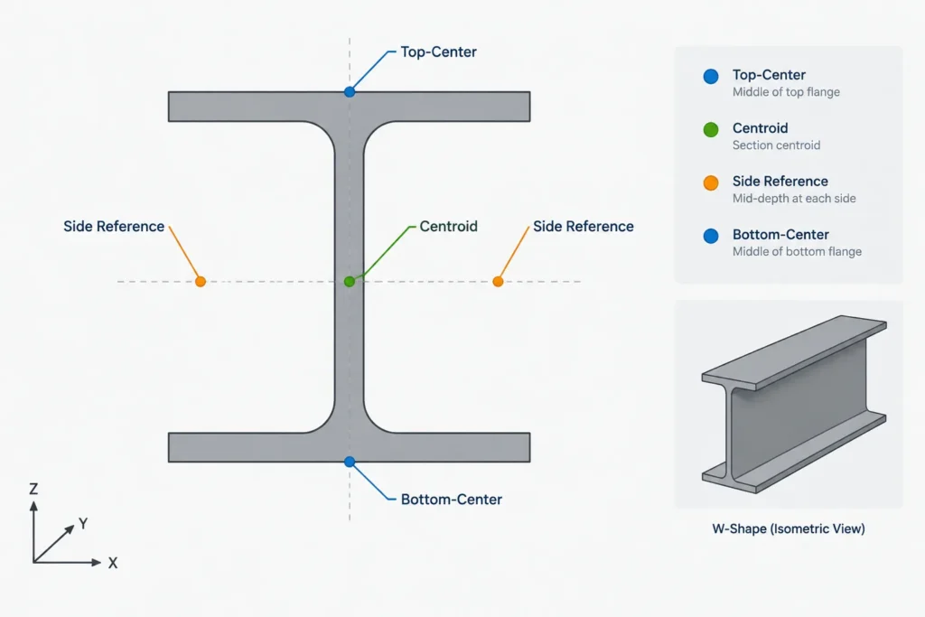
A cardinal point does not change the steel shape itself. It changes where the shape is placed relative to the member line. If the line remains fixed and the cardinal point changes, the section moves around that line.
This distinction matters when exchanging models. A receiving system may import the physical geometry correctly but interpret the original placement metadata differently. Conversely, matching placement lines do not guarantee that the visible steel occupies the same space.
How Placement Choices Affect Common Steel Shapes
| Shape | Useful placement references | Potential coordination issue |
|---|---|---|
| W or other I-shaped member | Centroid, top flange, bottom flange, web centerline | A depth change can move the top or bottom surface if the wrong reference is held |
| Rectangular or square HSS | Section center, outside face, corner | A width change can move cladding, connection plates, or adjacent framing |
| Round HSS or pipe | Section center or tangent reference | Center placement is natural, but face-based clearance dimensions still require checking |
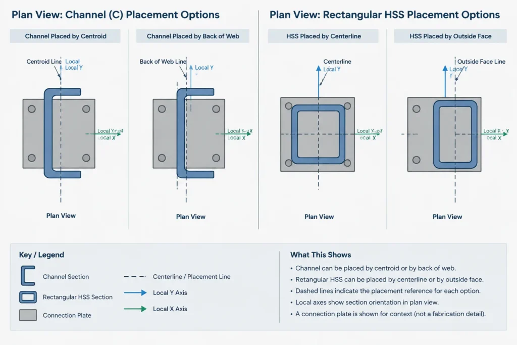
| Channel | Centroid, web centerline, back of web, flange extremity | The centroid does not generally lie at the web center, so center-based and web-based placement differ |
| Angle | Centroid, heel, leg face, leg corner | Unequal legs and rotated orientations can make generic left/right descriptions ambiguous |
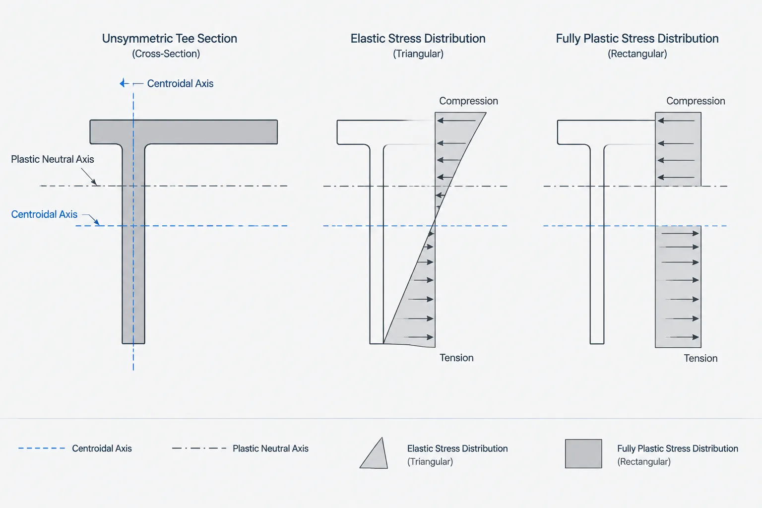
| Structural tee | Centroid, flange face, stem centerline | Centroidal placement may not preserve a supporting or connected face after a size change |
Insertion Point vs. Section Offset
An insertion point selects the base relationship between the member line and the section. An offset adds a translation to that relationship. The two controls can create similar final geometry, but they do not communicate the same modeling intent.
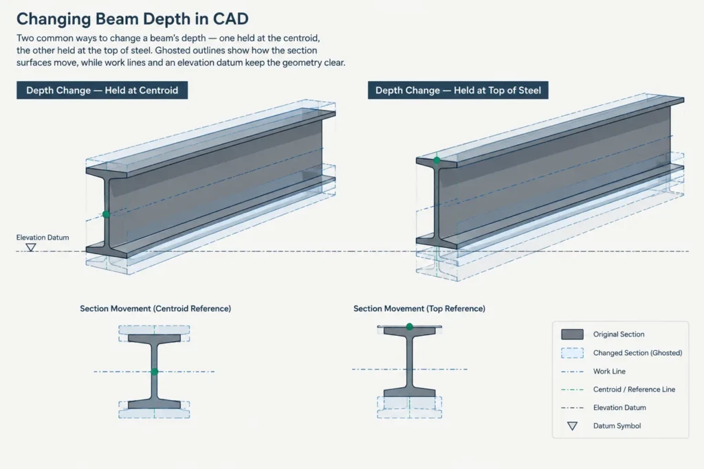
For example, a beam can be placed with its top-center reference on a framing elevation. It may also be placed by its centroid and shifted vertically until the top flange reaches the same elevation. Both models can look identical, yet they may react differently when the section changes.
Where practical, use an insertion rule that expresses the controlling design or detailing condition. Reserve offsets for real departures from that rule. This makes the model easier to inspect and reduces dependence on unexplained numerical adjustments.
Offsets Need a Coordinate Definition
An offset is incomplete without knowing the coordinate system in which it acts. It may be measured in global coordinates, view coordinates, or the member’s local section axes. A local horizontal offset can point in the opposite global direction when the member direction is reversed.
Before editing offsets, confirm:
- The member start and end direction
- The orientation of the local section axes
- The section rotation about the member line
- Whether offsets are applied locally or globally
- Whether end offsets and section-placement offsets are separate controls
Why Member-Size Changes Expose Placement Problems
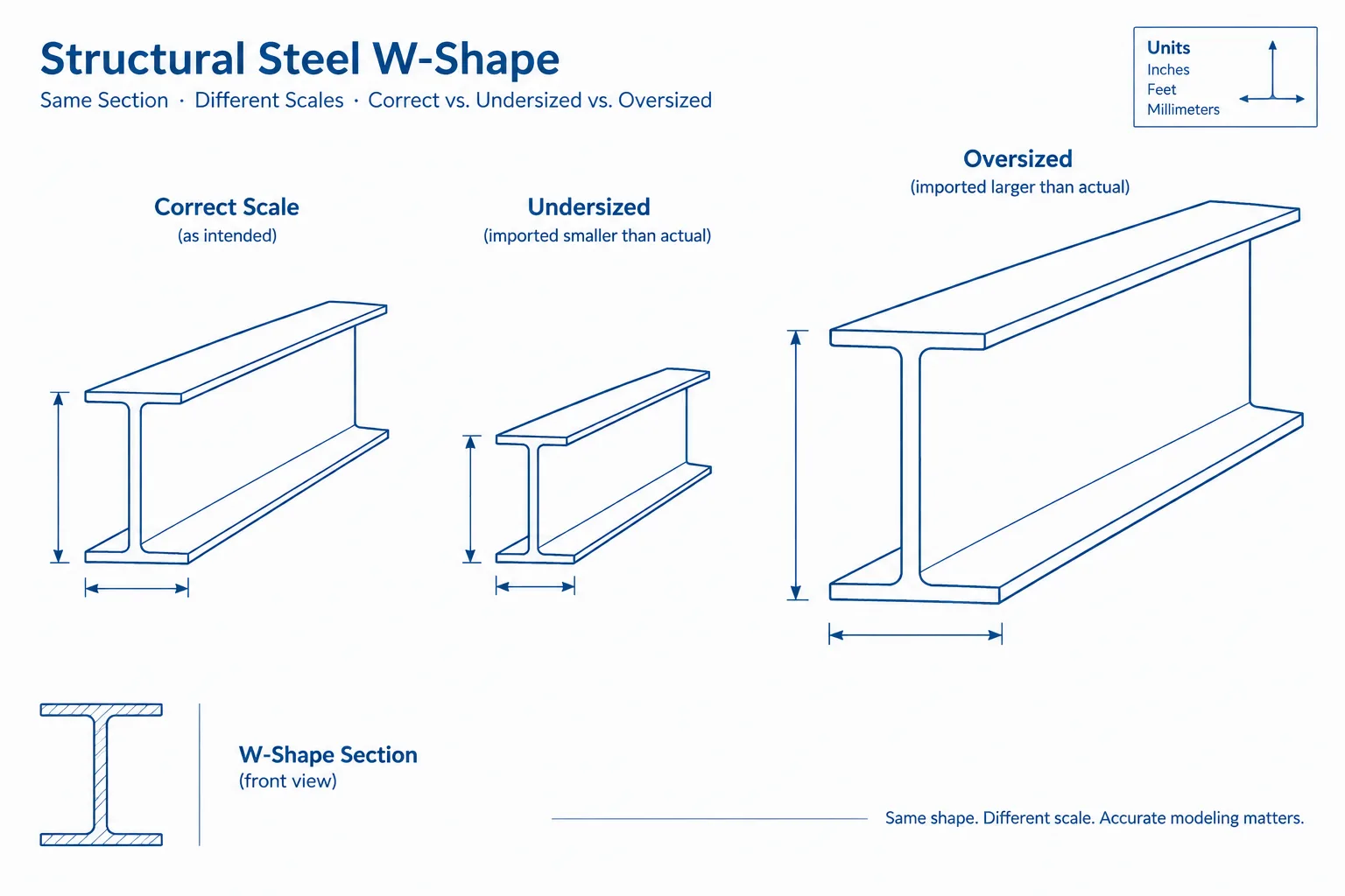
A member substitution is one of the fastest ways to reveal an unsuitable insertion point. If a beam is centered on its centroidal line, changing to a deeper section generally moves both the top and bottom surfaces relative to that line. If top of steel must remain fixed, the beam should instead use a top-based placement rule or be deliberately repositioned after the change.
The same principle applies horizontally. If the back of a channel must align with a plate, using a centroid-based placement can move the web face when the channel size changes. If the outside face of an HSS column controls an architectural clearance, centerline placement may require a revised offset whenever the section width changes.
There is no universally correct insertion point for every member. The appropriate choice depends on what must remain stable during design development and fabrication coordination.
Select the Datum That Represents Design Intent
A useful placement strategy starts by identifying the controlling datum rather than accepting the software default.
- Floor and roof beams: Top-of-steel control may be more important than preserving the section centroid.
- Columns: Grid or centerline placement may be appropriate when framing is organized around column centers, while face alignment may control at perimeter conditions.
- Girts and side rails: An exterior face may control alignment with enclosure systems.
- Channels supporting plates: The back of web or a flange surface may be the functional datum.
- Angles at edges: The heel, outside leg face, or connected leg may be more useful than the centroid.
- HSS framing: Centerline placement simplifies symmetric framing, but face-based placement may better preserve connection or clearance geometry.
The governing datum should also appear clearly in drawings. A carefully chosen model insertion point provides little benefit if dimensions refer inconsistently to centerlines, member faces, and grids.
Insertion Lines and Analytical Lines Are Not Interchangeable
An analytical model often represents members with idealized lines connected at theoretical nodes. A physical steel model represents the actual volume of the sections, including offsets needed for bearing, connection geometry, and alignment.
The analytical line may need to stay on a framing work line while the physical member is offset from it. Do not move an analytical reference solely to make the rendered steel look correct unless the modeling workflow specifically requires that relationship. Similarly, do not assume that a physical member’s insertion line defines the structural eccentricity used in engineering analysis.
When model information passes between design and detailing systems, coordinate both references: where the analysis line is located and how the physical section is positioned around it.
CAD and BIM Quality-Control Workflow
A reliable review should inspect member metadata as well as visible geometry.
- Identify the controlling datum. Determine whether the member is governed by a grid, centerline, top elevation, face, heel, web back, or connection plane.
- Verify section orientation. Confirm flange direction, channel opening, angle-leg orientation, HSS face alignment, and member start-to-end direction.
- Check the insertion setting. Read the descriptive placement control or consult the software diagram; do not rely on a cardinal-point number alone.
- Review offsets. Determine why each offset exists and whether it is expressed in local or global coordinates.
- Test a representative size change. Temporarily substitute another plausible shape and observe which faces move. Restore the specified shape after the test.
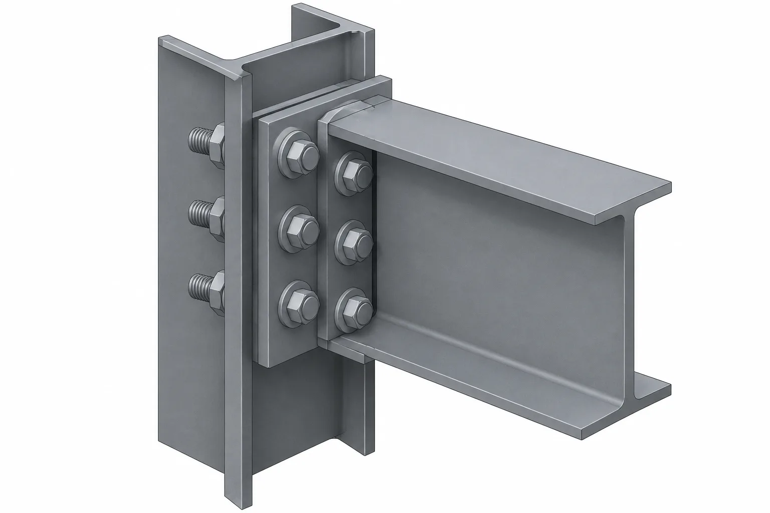
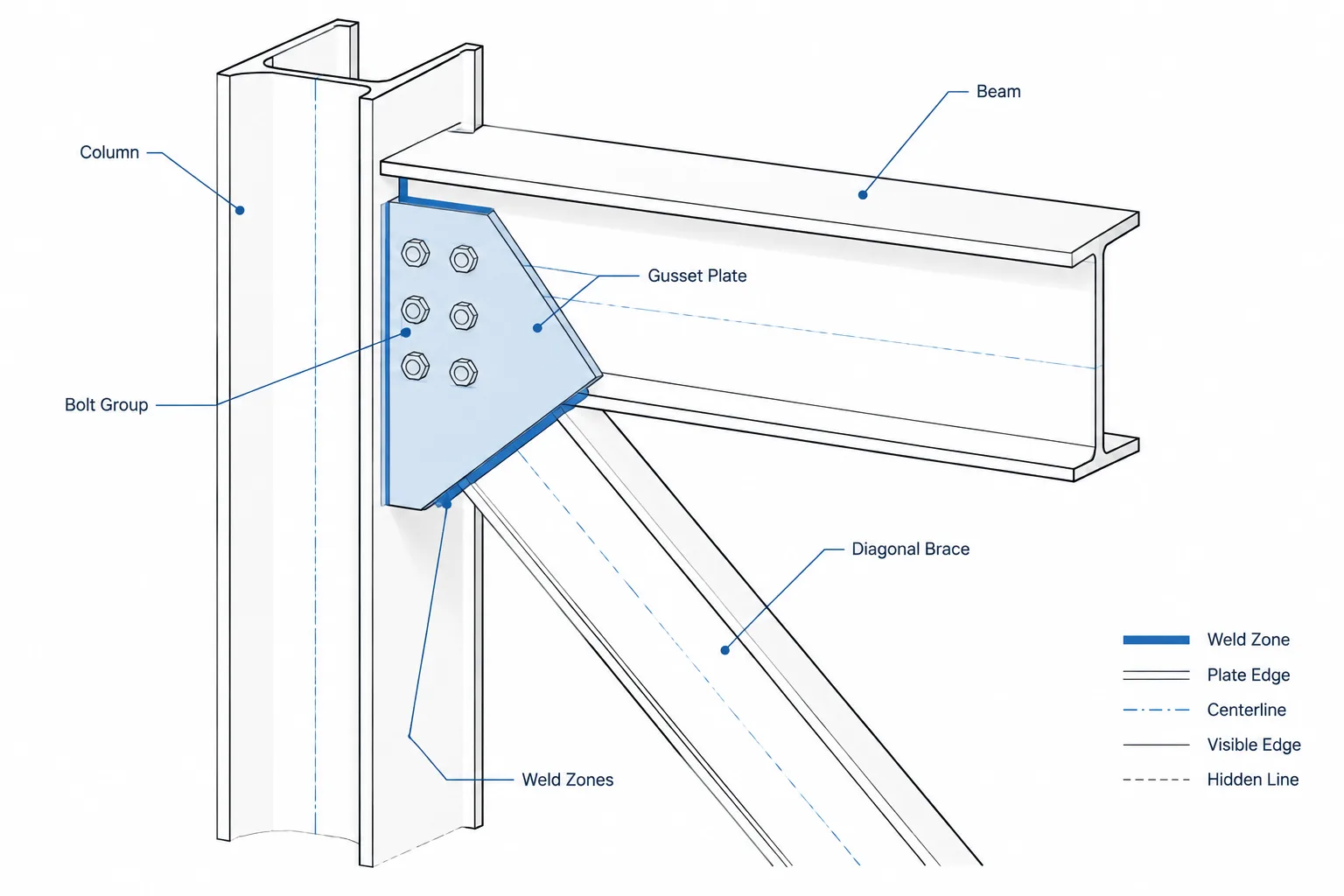
- Inspect member ends and connections. Confirm that setbacks, plates, bolts, copes, and supporting faces still align with the intended steel geometry.
- Compare model and drawing dimensions. Verify that dimensions are tied to durable datums rather than incidental shape edges.
Common Warning Signs
- Several members require unexplained offsets to align at the same elevation.
- Changing a beam size unexpectedly moves the floor-supporting surface.
- Channel webs do not stay aligned after substitutions.
- Mirrored or reversed members shift to the opposite side of a work line.
- Connection components remain in place while the steel shape moves around the insertion line.
- Plan dimensions reference one face while sections reference the member centerline.
- Imported members have correct endpoints but incorrect physical positions.
These symptoms do not always indicate a software error. They often point to a mismatch among insertion rules, local axes, rotations, and offsets.
Practical Takeaway
Steel member insertion points are not merely display settings. They define how section geometry relates to the lines used for layout, coordination, and modification. A good placement rule preserves the datum that matters when the member rotates, changes size, or passes between project participants.
Before issuing drawings or exchanging a model, verify the physical shape rather than only its centerline. Record unusual offsets, use descriptive datums where possible, and test how representative members respond to a shape change. These checks help keep shape-table data, CAD geometry, connection details, and drawing dimensions tied to the same steel.