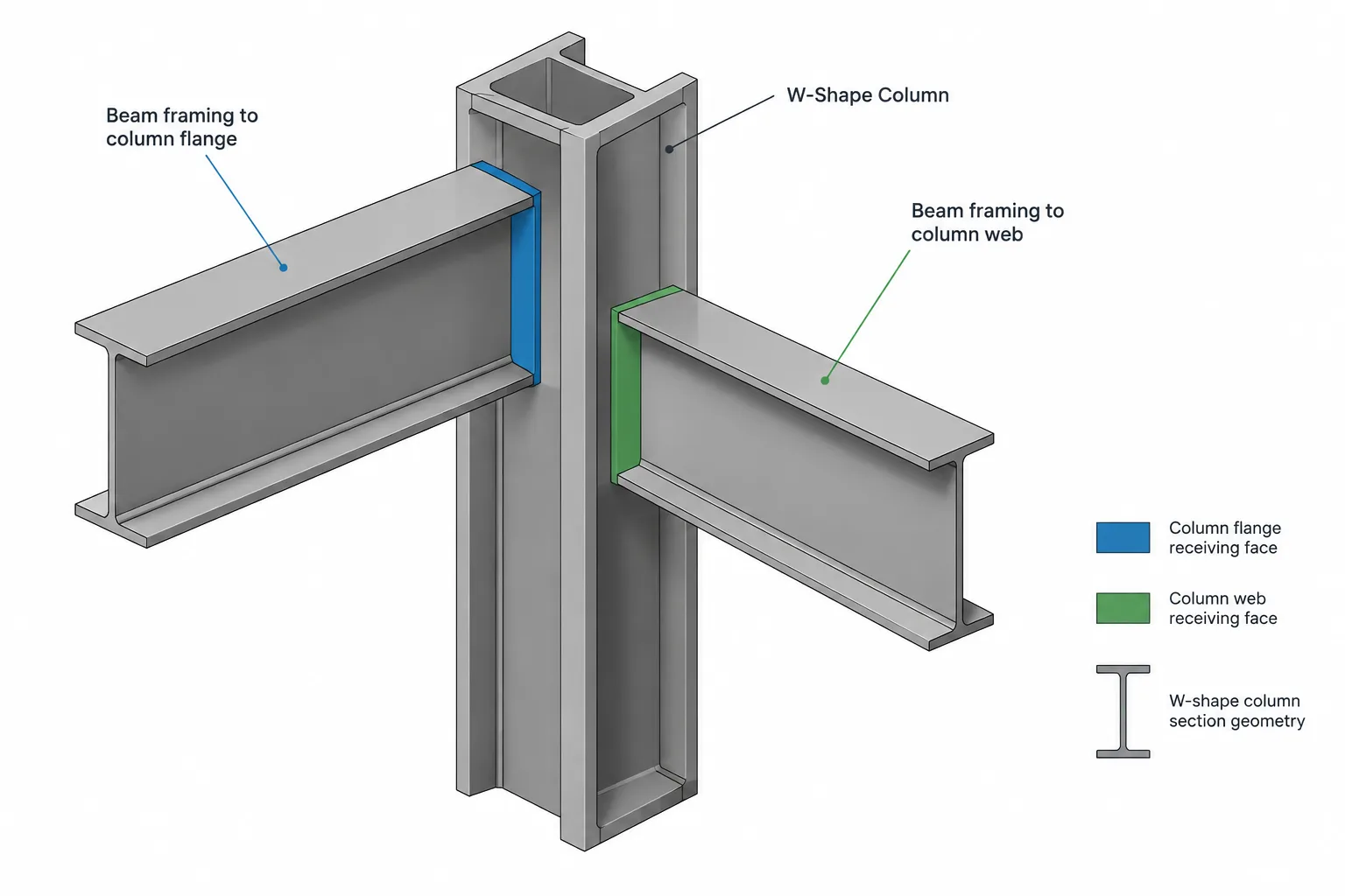
A beam-to-column connection is often described simply as a beam framing into a column. For design and detailing, however, the side of the column receiving the beam is a critical distinction. A beam connected at a column flange encounters different geometry, access, and load-transfer conditions than a beam connected at the column web.
This distinction affects connection selection, bolt placement, weld access, beam end preparation, and coordination with members arriving from other directions. It should be established before a detail is copied, modeled, or dimensioned.
What flange-side and web-side framing mean
For a typical W-shape column, the flanges form the two broad exterior faces of the section. The web runs between them. A beam approaching the exterior face of a column flange is a flange-side framing condition. A beam approaching perpendicular to the column web is a web-side condition, where the connection must generally fit in the space bounded by the column flanges.
The labels describe the column surface receiving the connection—not the orientation of the supported beam’s own web and flanges. In many conventional framing conditions, the beam web remains vertical regardless of which column face it approaches.
| Detailing issue | Beam to column flange | Beam to column web |
|---|---|---|
| Receiving surface | Exterior face of a column flange | Column web between the flanges |
| Connection space | Usually open in front of the flange face | Constrained by the column flange projections and rolled fillets |
| Fastener access | Often more direct, subject to adjacent framing | May be restricted by the column flanges and opposing connections |
| Typical geometric concern | Column flange width, thickness, and face alignment | Clear space between flanges, web location, and fillet clearance |
| Opposite-side coordination | Connections may interact through or around the column flange | Connections on both sides may compete for the same web region |
| Modeling risk | Connecting to the wrong flange face or offsetting from the wrong plane | Treating the web plane as if it were an unobstructed exterior face |
Beam framing to a column flange
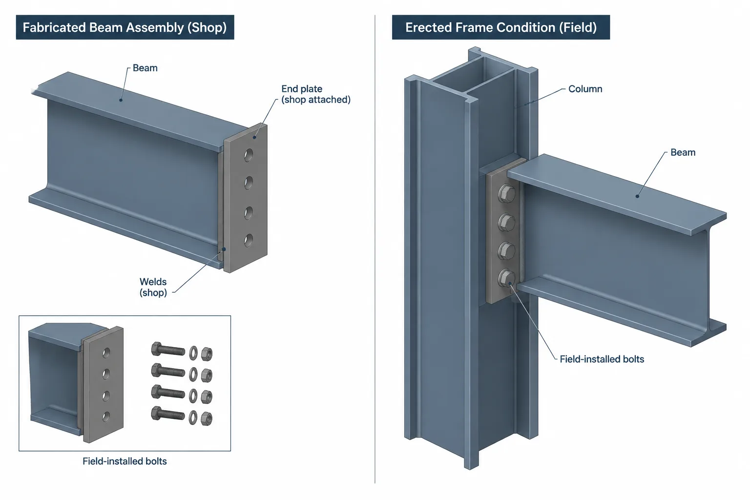
A column flange provides a relatively broad receiving face. Common connection concepts may include a single plate, angles, an end plate, or welded components, depending on the engineered connection and the intended force transfer. The apparent openness of the flange face does not eliminate the need for geometric checks.
Column flange width and connection fit
The connection components and bolt pattern must fit the available column flange geometry. A nominal column depth does not define its flange width, and columns within the same depth family can have significantly different proportions. Detailers should retrieve the actual section dimensions from a verified shape reference rather than scaling a section symbol.
Check whether bolt heads, nuts, weld returns, plate edges, and erection clearances remain within usable space. If another beam frames to the opposite flange, review both connections together even when they appear independent in plan.
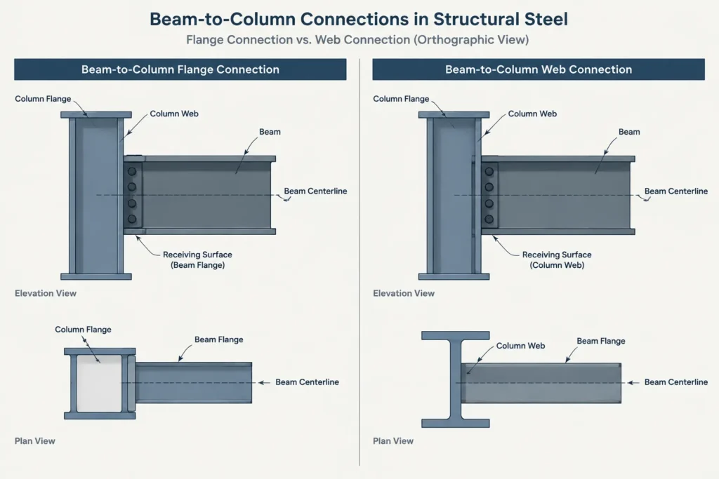
Column-face reference plane
A beam work point may be placed at the column centerline, but the physical beam end is normally controlled by the relevant column face and the connection geometry. Confusing the column centerline with the flange face can produce an incorrect beam length or connection setback.
In a CAD model, keep the analytical or layout work line separate from the physical end of steel. The distance between them depends on the actual column section, orientation, beam end condition, and connection arrangement.
Local column requirements
A connection delivering significant forces through a column flange may require engineering review of the flange, web, and surrounding column region. Continuity plates, stiffeners, doubler plates, or other reinforcement must not be added or omitted based solely on a typical detail. Their need, size, location, and attachment are design decisions.
Beam framing to a column web
A beam-to-column web connection is geometrically more confined. Although an elevation may show a simple beam end meeting a vertical column line, the three-dimensional condition includes column flanges projecting on both sides of the web.
Clear space between column flanges
The usable connection region is not simply the full clear depth suggested by sharp-corner CAD geometry. Rolled W-shapes include web-to-flange fillets, and connection plates, angle legs, welds, bolt heads, and installation tools must avoid those regions as required by the selected detail.
The supported beam flange may also approach or overlap the column flange region, depending on the relative beam and column sizes and elevations. A beam cope, flange cut, setback, or different connection arrangement may be needed, but it should follow the engineered geometry rather than an assumed standard solution.
Opposing beam connections
When beams frame into both sides of the column web at the same elevation, their connection components may occupy the same area. Potential conflicts include:
- Bolts or bolt holes attempting to use the same web location
- Shop welds obstructing connection material on the opposite side
- One-sided connections creating installation or tightening difficulties
- Different beam depths producing overlapping plates or angles
- Connection elevations that appear aligned in plan but differ in section
Both sides should be modeled or overlaid during connection development. Reviewing each beam independently can hide interference through the column web.
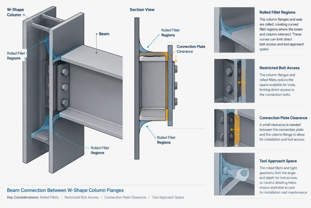
Access between the flanges
Access must be considered for fabrication as well as field erection. A bolt shown clearly in an elevation may sit too close to a column flange for practical tool access. Similarly, a weld symbol does not prove that the joint can be reached or deposited in the intended sequence.
Connection geometry should be reviewed in section and, when congested, in a three-dimensional view. A flat web-side elevation alone rarely communicates every obstruction.
Connection location does not define connection behavior
Flange-side versus web-side framing describes orientation, not structural behavior. Either condition may be associated with a simple shear connection or a connection intended to transfer additional forces, depending on the structural design.
Do not infer connection behavior merely because a beam meets a column flange. Likewise, do not assume that every web-side connection is a basic shear connection. The contract drawings, design criteria, reactions, connection schedules, and engineer’s details control the required force path.
This distinction is especially important when reusing details. A connection that fits geometrically at one column face may not provide the intended behavior at another face, and a visually similar detail may have different force-transfer requirements.
How to identify the condition on drawings
Start with the column orientation shown in plan. A W-shape column symbol should indicate the direction of its web and flanges, but schematic graphics can be ambiguous. Cross-check the plan against column schedules, framing elevations, sections, and the structural model.
Useful identification steps include:
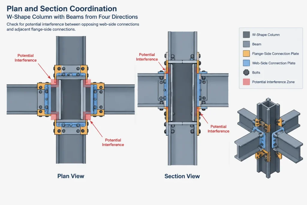
- Locate the column centerline and confirm the column shape designation.
- Determine which direction the column web runs.
- Trace the supported beam centerline toward the physical column section.
- Identify whether the beam reaches an exterior flange face or the web between flanges.
- Check for beams arriving from the opposite or adjacent faces.
- Verify top-of-steel elevations, slopes, offsets, and beam end conditions.
If the column is rotated, sloped, built up, or part of a skewed framing system, ordinary plan labels may be insufficient. Use a local section or model view rather than relying on conventional page orientation.
CAD and model workflow
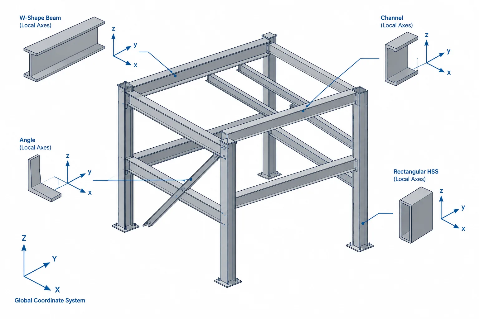
A reliable modeling process separates reference geometry from fabricated geometry. Begin with verified member sizes and orientations, then establish the column centerline, column faces, beam work line, and beam end plane.
- Insert the actual section geometry. Use verified dimensions rather than a generic I-shape outline.
- Confirm section rotation. Make sure the column web and flanges agree with the framing plan.
- Place the beam by its intended work line. Do not snap the beam end to a symbolic column line without checking the physical face.
- Develop the connection in three dimensions. Include relevant plates, angles, bolts, weld access zones, and beam cuts.
- Review adjacent faces. Display connections on all sides of the column, including members at nearby elevations.
- Generate sections from the coordinated geometry. Use sections to confirm fit instead of using an unverified two-dimensional typical as the source geometry.
CAD blocks and connection templates are useful starting points, but they should remain editable and tied to verified project geometry. Scaling a connection block to make it fit can alter hole sizes, edge relationships, and component thicknesses without making the result technically valid.
Drawing information that improves clarity
A clear beam-to-column detail should communicate the receiving column face, beam end location, connection component orientation, and relevant elevations. Depending on the detail, it may also need dimensions locating holes or plates from stable reference lines.
Avoid dimensioning critical connection geometry from a schematic edge that could change when the column size changes. Centerlines, work points, top-of-steel elevations, and explicitly identified column faces usually provide more dependable coordination references.
When flange-side and web-side details appear on the same sheet, label them by actual condition rather than presenting one as a universal typical. Small section cuts can prevent the fabricator or reviewer from having to infer the column orientation.
Final coordination checklist
- Is the beam framing to the column flange or column web?
- Does the modeled column rotation match the structural drawings?
- Was the beam end located from the correct physical face?
- Does the connection fit the verified column dimensions?
- Have rolled fillets and flange projections been considered?
- Are bolts, nuts, welds, and tools accessible?
- Do connections on opposite or adjacent faces interfere?
- Are beam flange cuts or copes shown only where required?
- Does the detail reflect the specified structural behavior?
- Have reinforcement requirements been confirmed by the responsible designer?
The practical difference between flange-side and web-side framing is much more than a ninety-degree change in plan. It changes the available connection space, the likely interferences, the reference planes used for member length, and the views needed to communicate the work. Identifying the condition early makes connection development, CAD coordination, and drawing review substantially more reliable.