A beam end that looks simple in one drawing view can become ambiguous when the member is skewed in plan, sloped in elevation, or affected by both conditions. The resulting cut plane controls member length, flange tip locations, web geometry, connection fit, and the dimensions needed for fabrication.
Clear treatment of steel beam end cuts begins by separating the member axis from the cut plane. A member may be sloped while retaining a square end cut, or it may be level with an angled end cut. Drafters should not infer one condition from the other.
Start with the member coordinate system
End-cut geometry is easiest to understand in a local coordinate system attached to the steel member. One local axis follows the member length. The other two axes correspond generally to the cross-section directions, such as the web depth direction and the flange width direction of a W-shape.
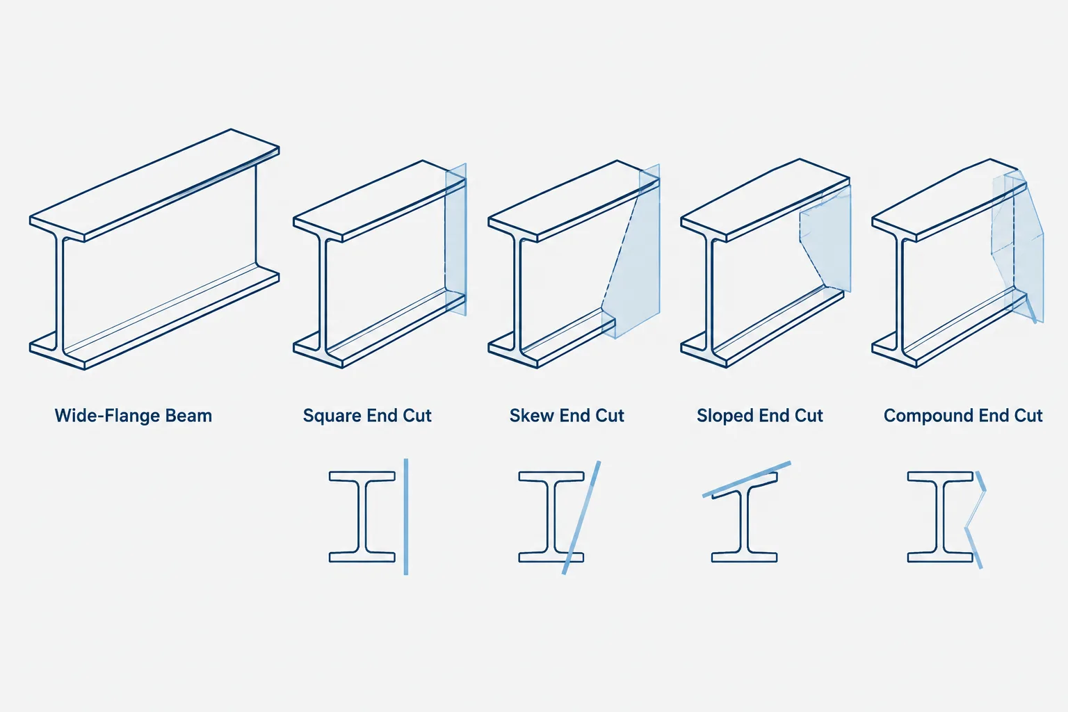
A cut plane can then be described by how it is oriented relative to the longitudinal axis:
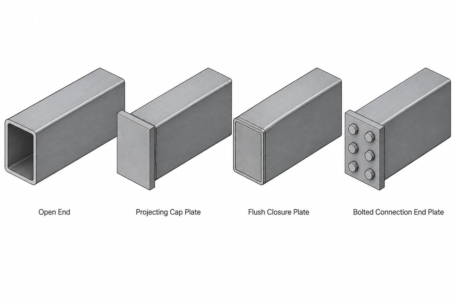
- Square cut: The cut plane is perpendicular to the member longitudinal axis.
- Skewed cut: The cut plane rotates across the member width when viewed in plan.
- Sloped cut: The cut plane rotates through the member depth when viewed in elevation.
- Compound cut: The cut plane is rotated in both plan and elevation.
These descriptions concern the end plane itself. They do not automatically describe the member’s orientation within the structure.
Square cuts on level and sloped members
A square cut is normal to the member axis. On a horizontal beam, it commonly appears vertical in elevation and straight across the section in plan. On a sloped member, however, a square cut follows the member’s local geometry and may not be vertical relative to the building coordinate system.
This distinction matters when a sloped beam frames to a vertical plate, column face, or another surface established in global coordinates. A square end cut and a vertical receiving surface are not necessarily parallel. The connection may require an angled end plane, a fitted plate, a varying gap, or another deliberate detail.
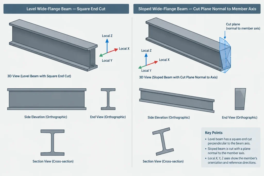
Do not label an end as square merely because it appears vertical in one projected view. Confirm that the plane is perpendicular to the actual three-dimensional member axis.
Skewed end cuts in plan
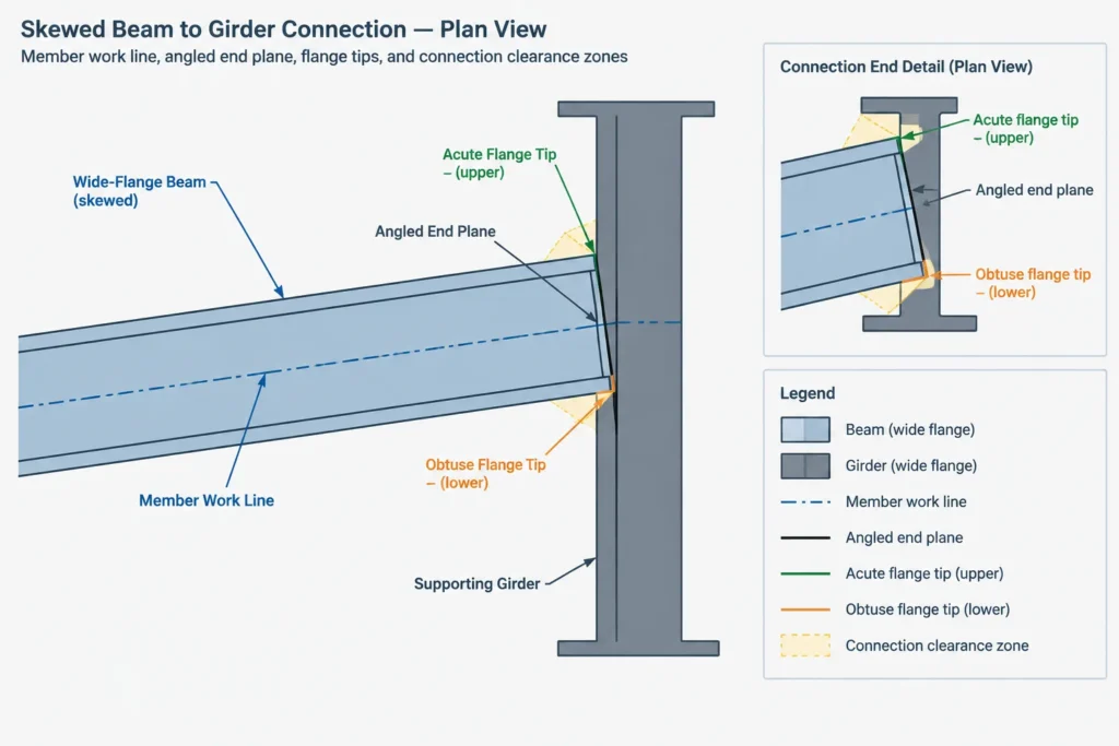
A skewed cut is commonly encountered where a beam frames obliquely into a girder, column, wall line, or edge member. In plan, the end line is not perpendicular to the beam work line. Across a wide flange, one flange tip therefore extends farther than the opposite tip.
The skew affects more than the visible end line. It can influence:
- Overall material length and saw-cut setup
- Flange tip clearances at the supporting member
- Web connection setback and plate positioning
- Access for bolts and welding
- Cope geometry near the acute side of the intersection
- Whether the end plane interferes with a supporting flange, web, stiffener, or weld
A plan angle by itself may not fully define fabrication geometry unless its reference is clear. State whether the angle is measured from a square cut, from the member centerline, or from a building grid or supporting face. The drawing should also identify the point controlling member length.
Sloped end cuts in elevation
A sloped end cut rotates through the member depth. It may occur when the end must align with an inclined surface or when a level or sloping member meets another component at a vertical angle.
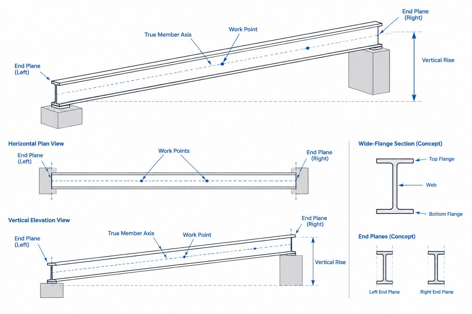
On a W-shape, the top and bottom flange intersections with the cut plane occur at different longitudinal positions. Consequently, a single end location can be misleading unless the drawing establishes whether it refers to the member work point, web centerline, top flange, bottom flange, or another defined reference.
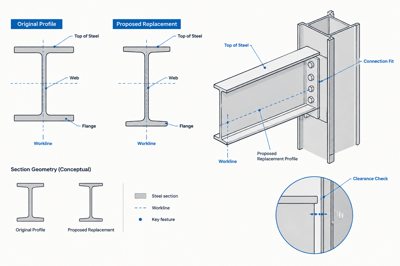
Sloped cuts also deserve attention around rolled fillets. A theoretical planar cut may pass through flange-to-web fillet regions, and simplified sharp-corner CAD outlines may not reveal the available clearance. Where fit depends on those regions, use verified shape geometry and coordinate the connection detail rather than relying only on a schematic section profile.
Compound cuts require a three-dimensional check
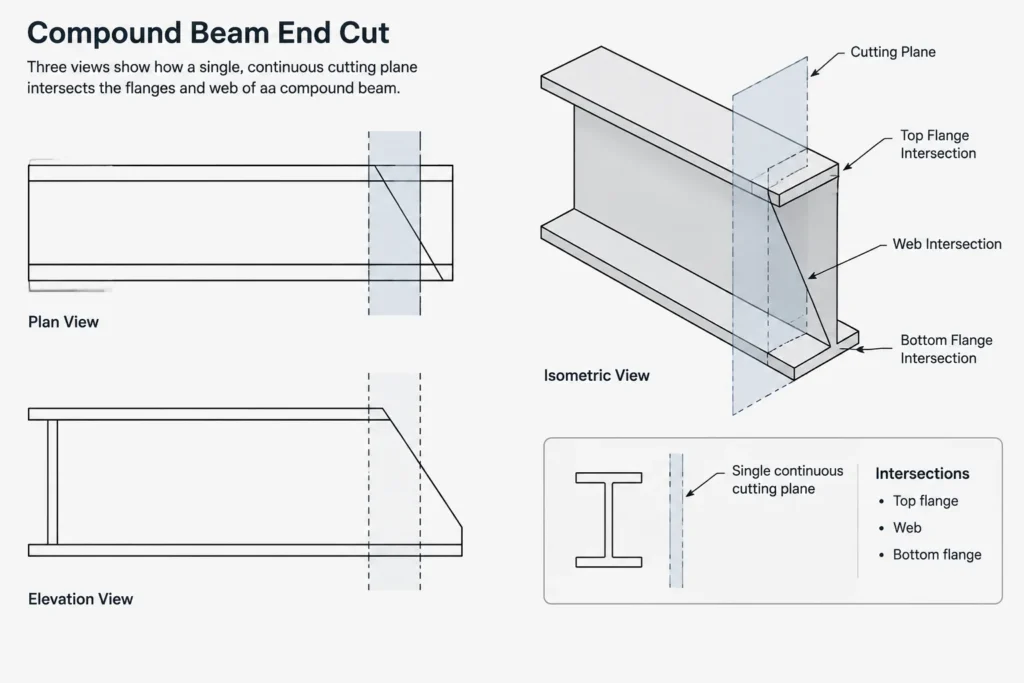
A compound end cut is rotated in both plan and elevation. Neither a plan view nor an elevation view alone shows its true shape. Projected end lines can make the cut appear simpler than it is, while flange tips and web edges terminate at different longitudinal coordinates.
Compound geometry should be checked in a three-dimensional model or by another controlled geometric method. Useful review views include an isometric view, a view normal to the cut plane, and separate plan and elevation projections. The goal is not merely to make the graphics look correct, but to verify the actual intersection of the cut plane with the steel profile.
| End condition | Typical controlling view | Primary detailing concern |
|---|---|---|
| Square cut | Local side or section view | Confirm the plane is normal to the member axis |
| Skewed cut | Plan | Identify the angular reference and unequal flange-tip positions |
| Sloped cut | Elevation | Identify which depth location controls member length |
| Compound cut | Model and multiple projections | Define the full plane rather than relying on one projected angle |
End cut, miter, and bevel are not interchangeable terms
Shop language varies, so descriptive geometry is safer than terminology alone. A miter often describes angled cuts that allow two pieces to meet along a joint, but it does not by itself define the cut plane or the reference angle. A bevel often refers to edge preparation for welding rather than an angled cut through the entire member.
If a member has an angled end and also requires weld preparation, show those as separate requirements. The overall end plane defines the member termination; the edge preparation defines the local treatment of an edge. Combining them under a general bevel note can create avoidable shop questions.
Choose a reliable length reference
An angled end has no single natural end coordinate because different points on the section terminate at different locations. A fabrication drawing should therefore establish a reproducible reference. Depending on the detail, that reference may be:
- The intersection of the member work line and cut plane
- The web centerline at the end plane
- A designated flange edge or flange tip
- A connection plate face
- A theoretical work point beyond the physical member end
The chosen reference should agree with the dimensioning strategy used elsewhere on the drawing. Mixing centerline dimensions, extreme-point dimensions, and work-point dimensions without explicitly connecting them can produce apparent discrepancies even when the model is geometrically correct.
Modeling steel beam end cuts in CAD
In a three-dimensional workflow, model the full member profile along its true axis and use a defined plane to create the end cut. Avoid independently trimming visible edges in different views; that approach can produce projections that look acceptable but do not represent one consistent plane.
For a two-dimensional workflow, construct the geometry from the member axis and the stated cut orientation. Project critical intersection points between plan, elevation, and section views. Do not assume that an angle measured in one view is the true angle of a compound plane.
Simplified CAD blocks can be useful for layout, but they should not be treated as fabrication geometry without verification. Generic profiles may omit rolled fillets, corner radii, and other shape features that affect close-fitting cuts or connection components.
What to show on a shop drawing
The drawing must communicate enough information for the cut to be reproduced and checked. The exact combination depends on project practice, but useful information commonly includes:
- Member designation and orientation
- Member work line and relevant work points
- Plan skew and elevation slope where applicable
- A clear angular or linear definition of the end plane
- The reference point used for member length
- End setbacks, gaps, or connection plate locations
- Copes, flange cuts, web cuts, and weld preparation shown separately
- End identification when the two ends differ
- Supporting geometry needed to explain fit
When an angle could be interpreted in more than one way, supplement it with linear dimensions or a detail view. Redundant information should agree and should be used deliberately, not added as uncontrolled duplication.
Practical end-cut review checklist
- Is the member axis correct in three dimensions?
- Is the end square to the member or aligned with a global surface?
- Are plan skew and elevation slope treated as separate conditions?
- Does the modeled cut represent one continuous plane?
- Is the member-length reference explicitly identifiable?
- Have both flange tips and the web termination been checked?
- Are rolled fillets or HSS corner geometry relevant to fit?
- Are copes and weld preparations distinguished from the main end cut?
- Is there clearance for the connection, supporting member, bolts, and weld access?
- Can the shop reproduce the geometry without measuring from a rendered view?
Clear geometry prevents downstream rework
Steel beam end cuts are best detailed as planes tied to defined member and project references. Terms such as square, skewed, sloped, mitered, or beveled can support communication, but they should not replace geometry.
By defining the member axis, cut-plane orientation, controlling length point, and connection clearances, a drafter creates information that can be checked consistently in the model, on the shop drawing, and during fabrication. That approach is especially important for skewed and compound conditions, where a convincing projection may still conceal an incorrect three-dimensional cut.