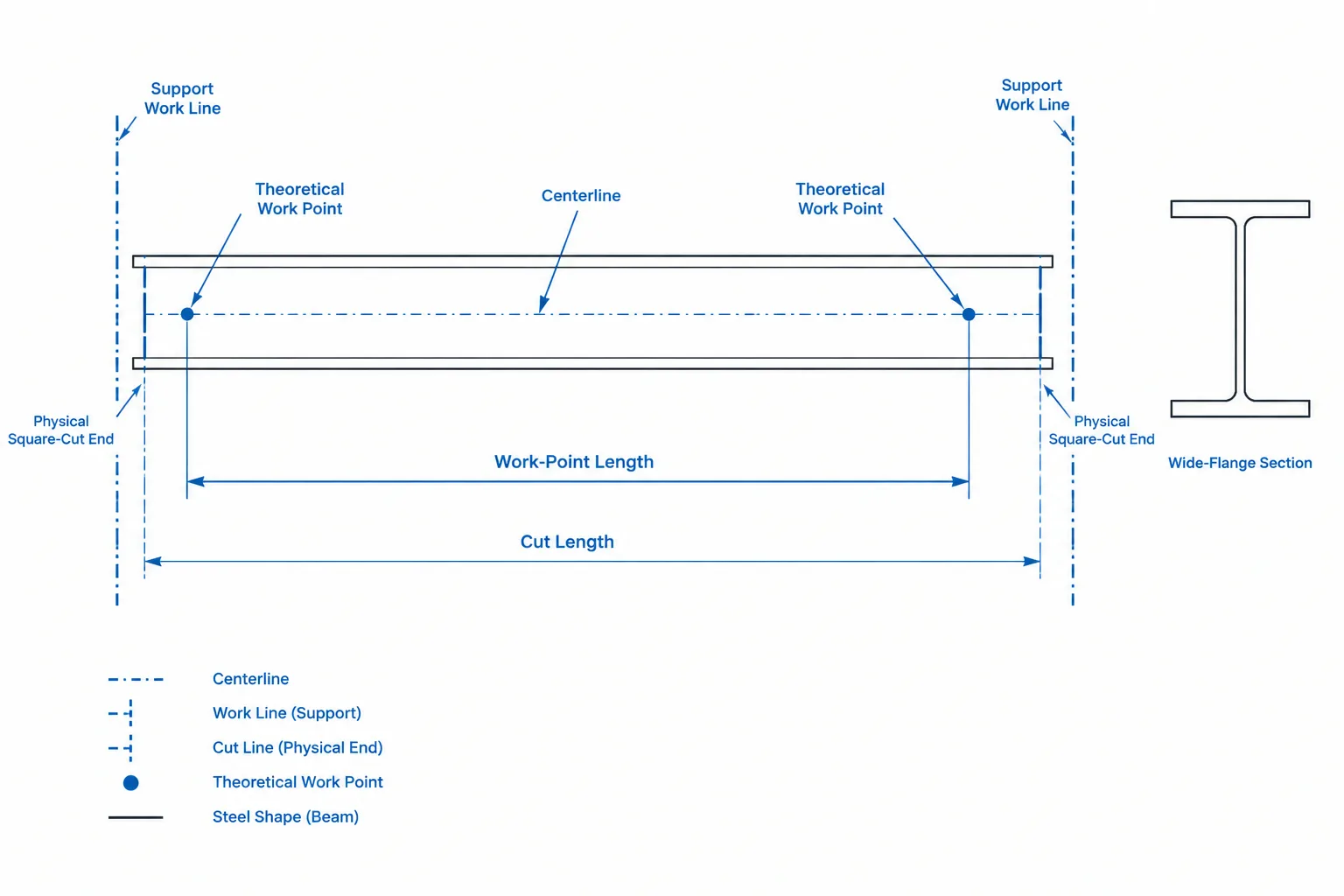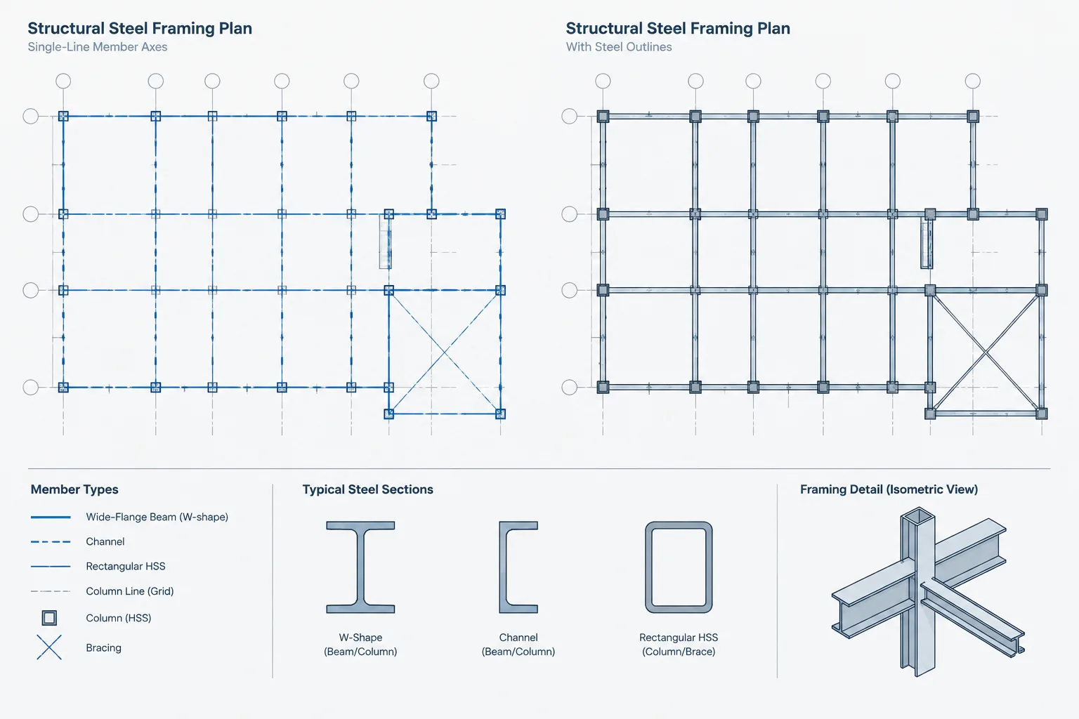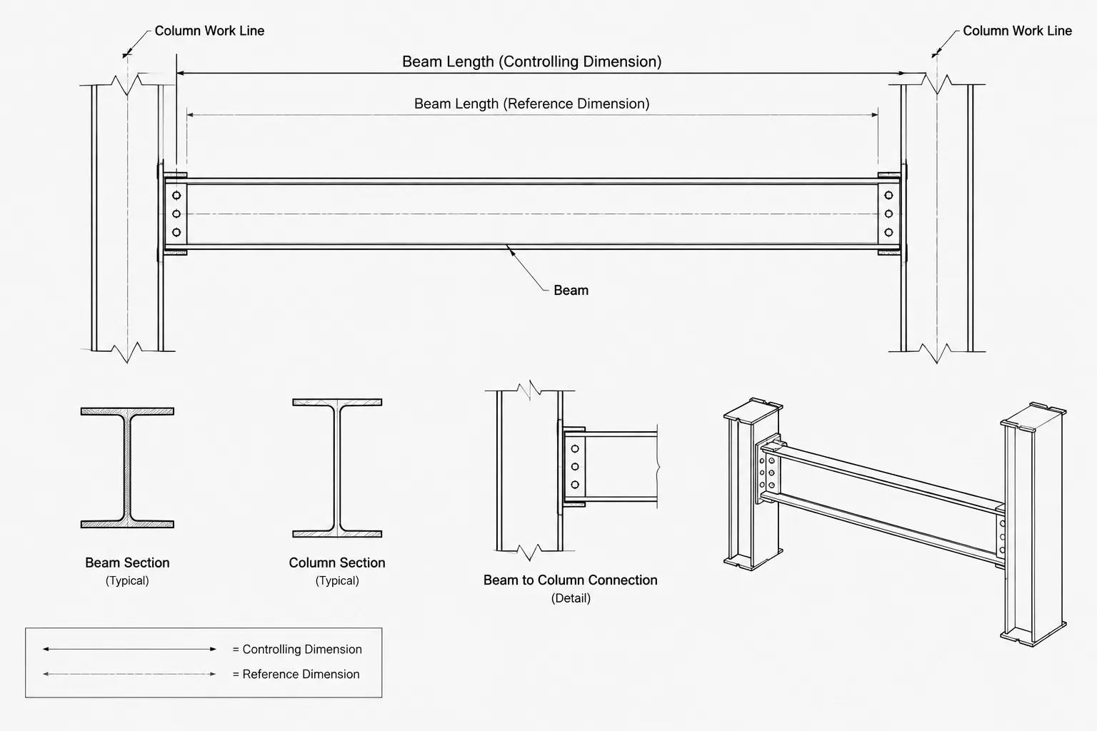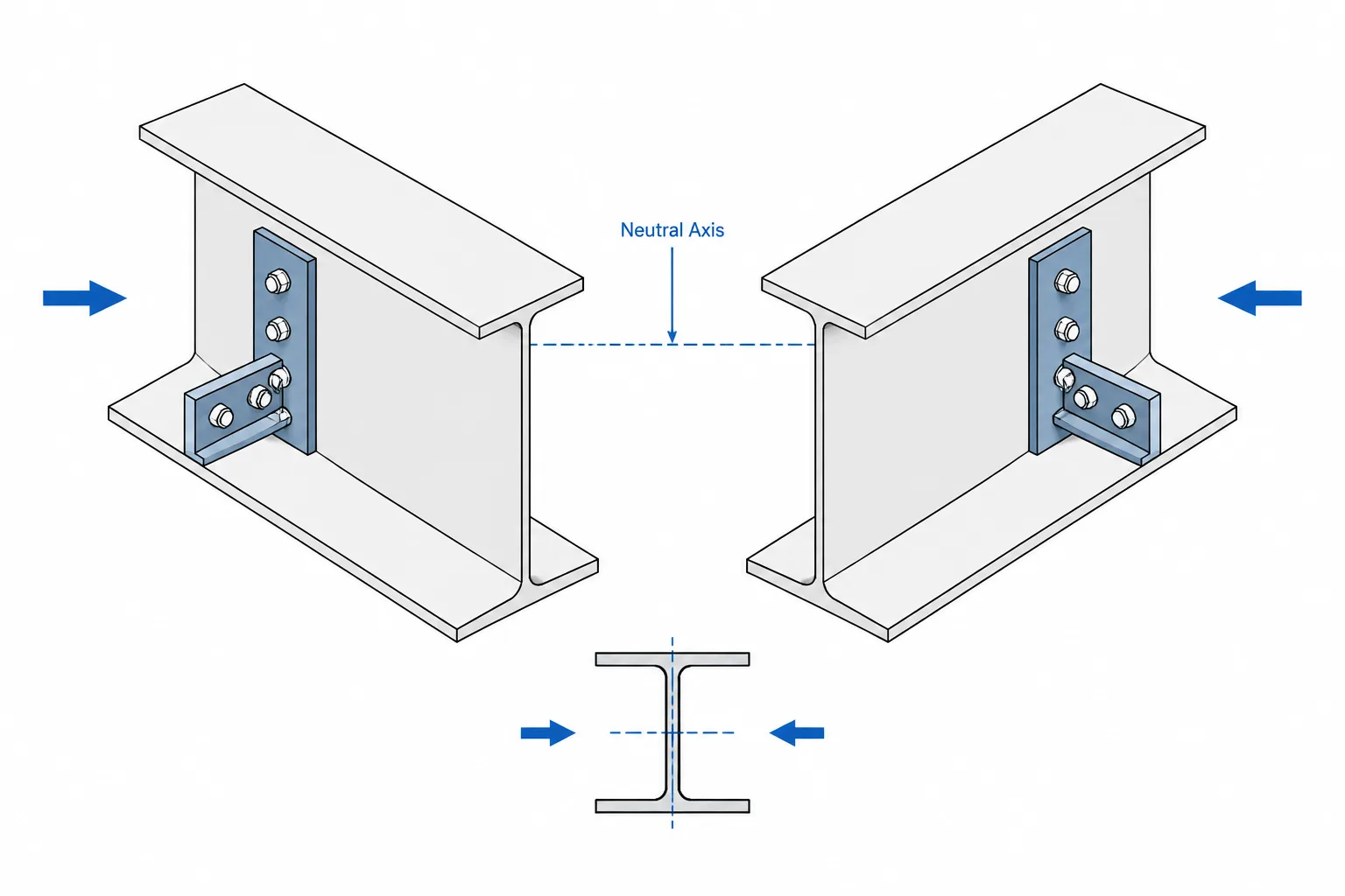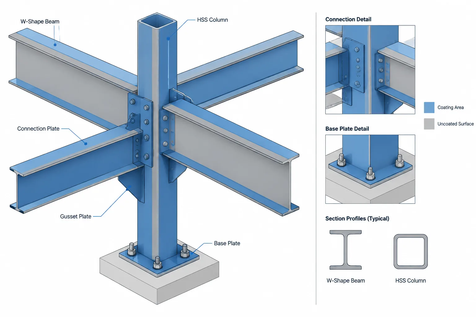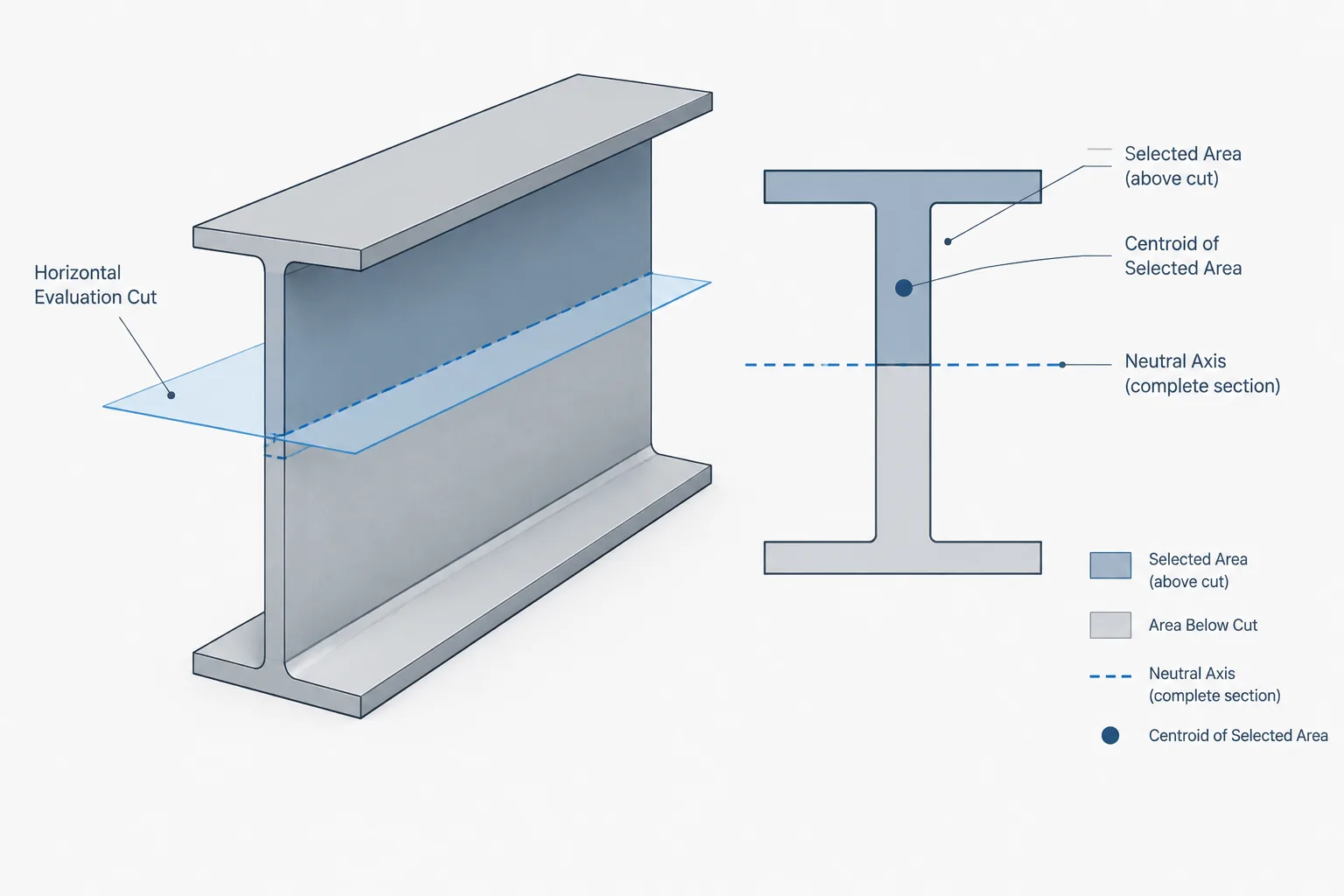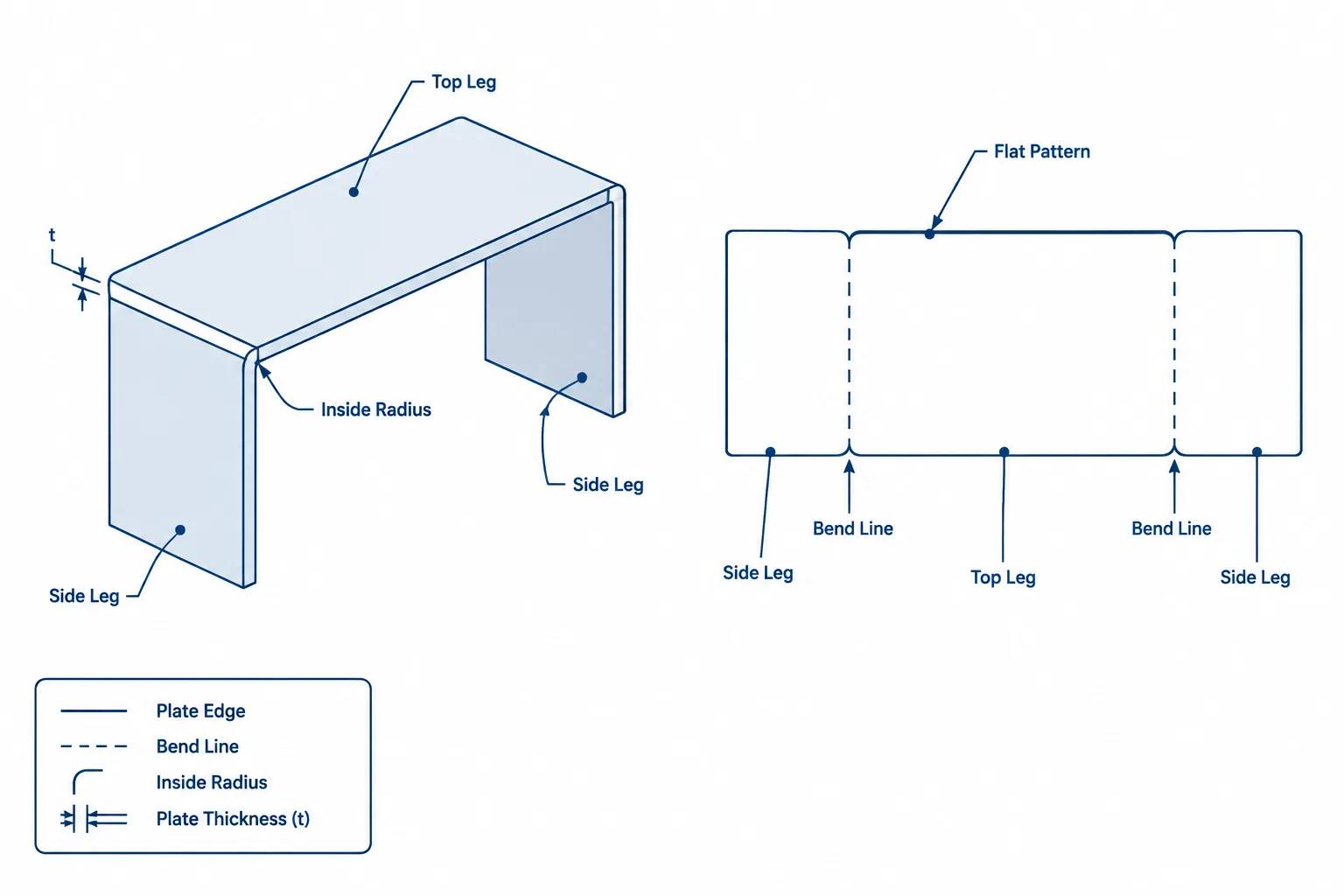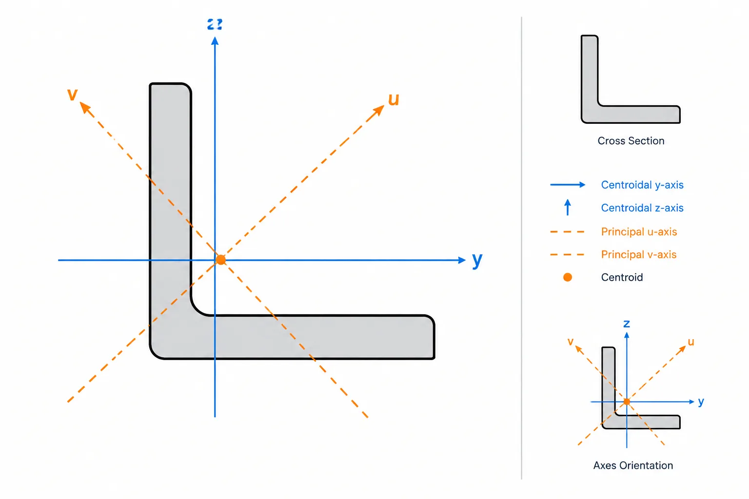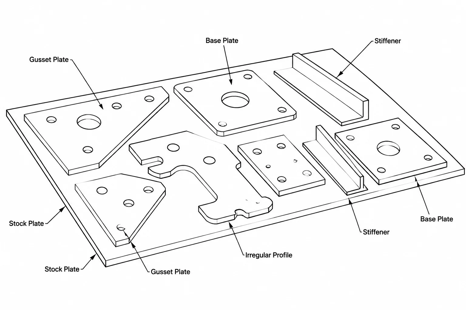
Structural steel plate nesting is the process of arranging individual plate parts on available stock material for cutting. Although nesting is often treated as a fabrication task, decisions made in the detailing model or CAD file can affect material use, part identification, cutting data, and revision control.
A good workflow separates three ideas that are easily confused: the plate’s mill rolling direction, the orientation of a part within the assembly, and the rotation used to nest that part on a stock sheet or plate. These directions may coincide, but they do not automatically mean the same thing. Clear documentation helps the detailer, fabricator, and cutting operator understand which orientations are functionally important and which may be changed to improve material utilization.
What Is Plate Nesting?
Nesting places multiple part profiles within the usable boundary of a stock plate. The goal is usually to use material efficiently while maintaining the clearances and allowances required by the selected cutting and handling process.
A nest may contain rectangular plates, gussets, stiffeners, base plates, connection plates, and irregular profiles. The arrangement must account for more than the theoretical outline of each part. Fabrication planning may also consider:
- Cutting kerf and process-specific separation between profiles
- Stock plate edges and usable material boundaries
- Areas reserved for test pieces, identification, or handling
- Heat distribution and the cutting sequence
- Common-line cutting policies, where permitted by the fabricator
- Part stability while cutting small or slender pieces
- Material grade, thickness, heat identification, and traceability
- Whether a part is allowed to rotate, mirror, or share a nest with other parts
The cleanest geometric arrangement is therefore not always the best fabrication arrangement. Nesting should be completed using the fabricator’s equipment, procedures, and verified stock information rather than from geometry alone.
Three Directions That Should Not Be Confused
Mill rolling direction
Rolling direction describes the direction in which the plate was processed at the mill. When rolling direction is relevant to a project requirement, fabrication procedure, material test condition, or engineered detail, it must remain identifiable through detailing and cutting.
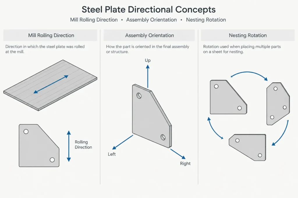
Do not infer rolling direction from the long side of a CAD rectangle. A stock plate can be represented at any rotation in a drawing, and a cropped model view does not establish how the physical plate was rolled. The direction must come from controlled material information or fabrication documentation.
Assembly orientation
Assembly orientation describes how the finished part sits in the fabricated member. A gusset may have a top edge, a connection edge, and a face that must remain oriented toward a particular side of an assembly. A base plate may contain an asymmetric hole pattern or an offset shear element. These features can make two apparently similar parts left-handed and right-handed.
Assembly orientation is normally communicated through part drawings, assembly views, piece marks, match marks, and dimensions. It does not by itself establish rolling direction.
Nesting rotation
Nesting rotation is the angle at which a part profile is placed on stock material. If no directional restriction applies, rotating a part may reduce scrap. If rolling direction, surface condition, bevel orientation, or another controlled feature matters, unrestricted rotation may be inappropriate.
Mirroring requires even greater care. Rotation preserves a part’s handedness; mirroring reverses it. A mirrored profile may place holes, bevels, counters, notches, or connection features on the wrong side even when its outside boundary appears to fit.
When Part Orientation Becomes a Controlling Requirement
Many ordinary plate parts can be nested in multiple orientations, but the detailer should not assume that every part is freely rotatable. Orientation may become controlling when the contract documents, engineering instructions, purchasing requirements, or fabrication procedures identify a directional condition.
Examples of conditions that warrant explicit coordination include:
- A specified relationship between a part and the plate rolling direction
- Directional material testing or documented toughness requirements
- Cold bending or forming that must follow a defined material orientation
- One-sided bevels, countersinks, or machined surfaces
- Surface treatments or exposed-face requirements
- Left-hand and right-hand assemblies
- Asymmetric hole patterns or slots
- Parts requiring retained material identification
- Profiles whose cutting orientation affects later fit-up or welding access
The presence of one of these conditions does not establish the required direction by itself. It signals that the controlling documents and responsible parties must define the requirement before cutting data is released.
Part Marks, Heat Numbers, and Traceability
A part mark identifies a fabricated component within the drawing and production system. A heat number or comparable material identifier connects stock material to its production and certification records. They serve different purposes and should not be used interchangeably.
| Identifier | Primary purpose | Typical control point |
|---|---|---|
| Part mark | Links a cut part to drawings, assemblies, and bills of material | Detailing and fabrication tracking |
| Assembly mark | Identifies a fabricated member or shipping assembly | Shop assembly and erection planning |
| Material identifier | Links stock or parts to material records | Receiving, inventory, cutting, and quality control |
| Nest or cutting job identifier | Links profiles to a particular cutting file or production batch | Cutting operation and revision control |
When traceability must continue after a plate is subdivided, the shop needs a procedure for transferring or recording identification. A CAD label alone does not guarantee physical traceability. Conversely, repeatedly engraving information into every part may not be appropriate unless the marking method and location are accepted for that work.
Preparing CAD Geometry for Nesting
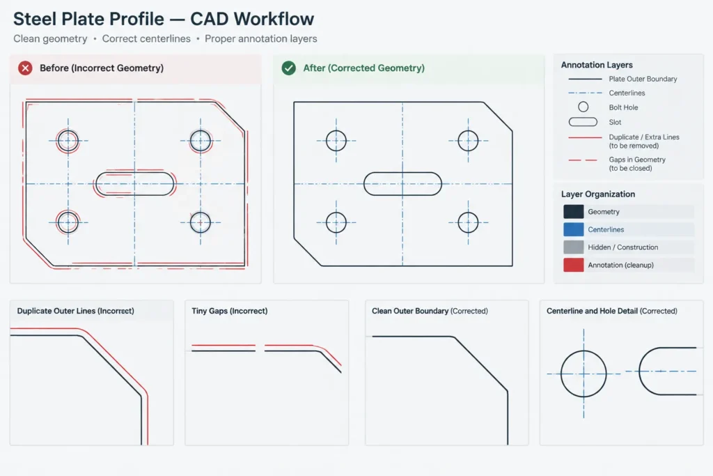
A reliable cutting profile should be geometrically clean before it reaches nesting software or CNC preparation. The source drawing can contain dimensions, centerlines, weld symbols, and notes, but the cutting geometry should be distinguishable from annotation.
Use closed, unambiguous profiles
Outside boundaries and internal cutouts should form closed loops without duplicate segments, tiny gaps, or overlapping entities. Intersections that look correct at drawing scale can still produce invalid toolpaths. Splines, ellipses, and complex curves may also require conversion or verification for the intended downstream system.
Keep design geometry separate from process offsets
The detailed part should normally represent the required finished geometry. Kerf compensation, lead-ins, tabs, and cutting sequence are process decisions that should be added through the fabricator’s controlled workflow. Building an assumed kerf offset into the original part outline can cause confusion or double compensation.
Define faces and bevels clearly
A profile view does not always communicate which face receives a bevel or other one-sided operation. The drawing or model data should identify the relevant face, edge, and orientation. If a part can be turned over during fabrication, that operation should not be confused with mirroring its geometry.
Choose a stable coordinate reference
Place the part relative to a logical origin or datum so that exported geometry can be checked easily. A consistent reference also helps compare revised profiles, hole coordinates, and overall extents. Arbitrary coordinates far from the working origin can create avoidable exchange and inspection problems.
A Practical Release Workflow
- Confirm material information. Verify plate thickness, material designation, and any special purchasing or traceability notes against the controlled project documents.
- Review directional requirements. Determine whether rolling direction, exposed face, forming direction, or handedness must be maintained.
- Validate the part profile. Check outside edges, holes, slots, notches, radii, bevel references, and closed-loop geometry.
- Assign unique identification. Coordinate part marks and revision status with the bill of material and assembly drawings.
- Set nesting permissions. Indicate whether rotation or mirroring is allowed rather than leaving the decision implicit.
- Export controlled geometry. Use the format and layer or entity conventions required by the fabricator.
- Review the resulting nest. Confirm stock identity, part quantities, orientation, and revision before production release.
- Archive the released data. Retain enough information to identify which drawing revision and cutting file produced the parts.
Common Plate Nesting Errors
- Treating rotation and mirroring as equivalent: A mirrored asymmetric plate can become the wrong hand.
- Assuming the CAD X-axis is rolling direction: Model coordinates do not prove physical material orientation.
- Exporting drawing clutter: Dimensions or centerlines can be mistaken for cut geometry if layers and entities are poorly controlled.
- Nesting mixed revisions: Visually similar profiles may contain changed holes, edge shapes, or bevels.
- Embedding assumed kerf in part geometry: This can alter the intended finished size when compensation is applied again.
- Losing material identity after cutting: A nest layout does not replace the shop’s traceability procedure.
- Optimizing scrap without considering handling: Very tight arrangements may complicate cutting, lifting, marking, or part removal.
What the Detailer Should Communicate
The detailer does not need to prescribe every cutting-machine decision. The goal is to provide accurate finished-part geometry and clearly identify restrictions that affect fabrication. Notes should focus on requirements rather than assumptions about a particular machine or nesting program.
When orientation is not controlled, allowing the fabricator to rotate parts can support efficient material use. When orientation is controlled, the reason and reference direction should be unmistakable. A simple directional arrow is useful only if its meaning is defined—such as rolling direction, member longitudinal direction, top of assembly, or exposed face.
Structural steel plate nesting works best as a coordinated handoff. Clean CAD profiles, controlled revisions, distinct identifiers, and explicit orientation rules let the fabricator optimize stock without changing the design intent.