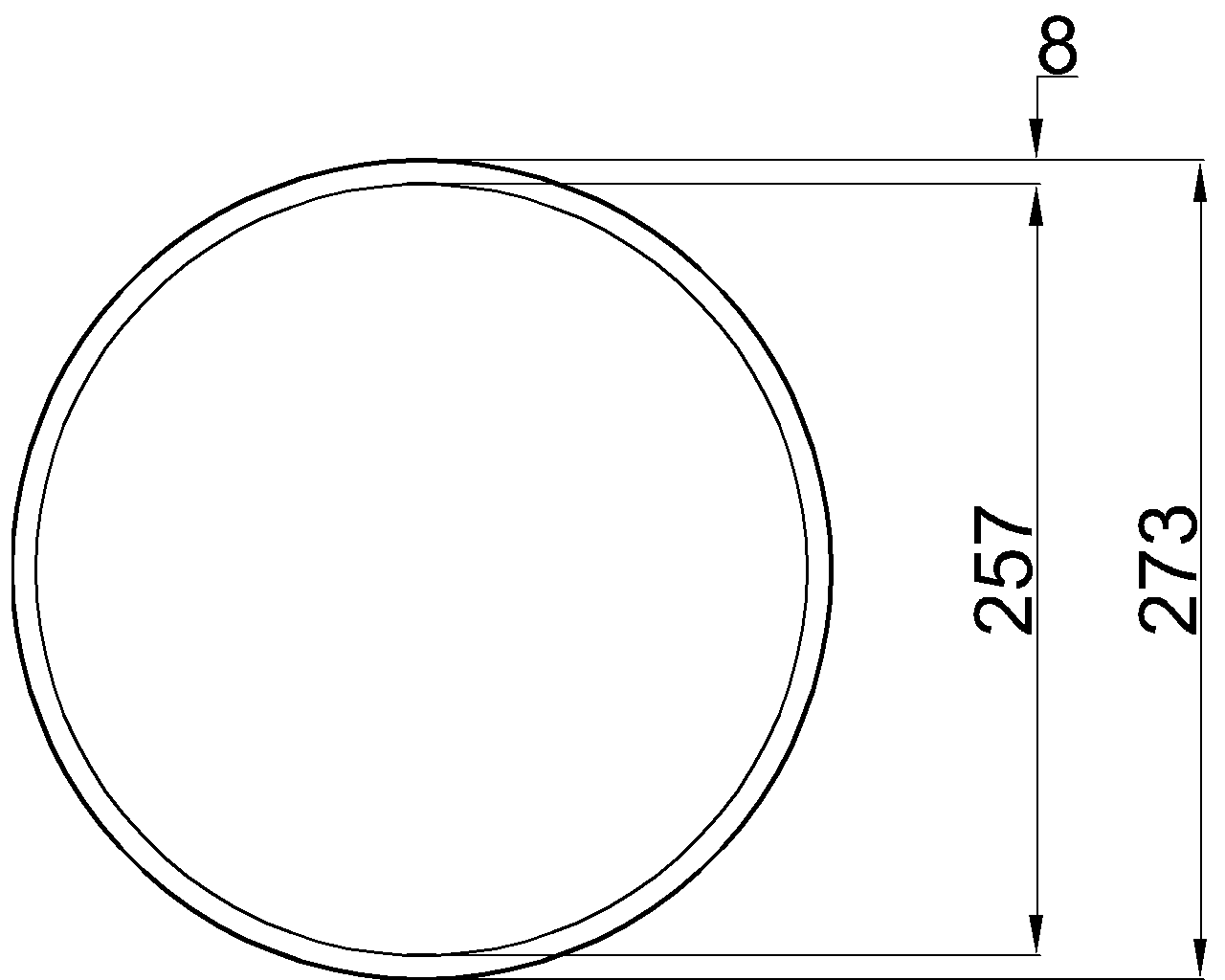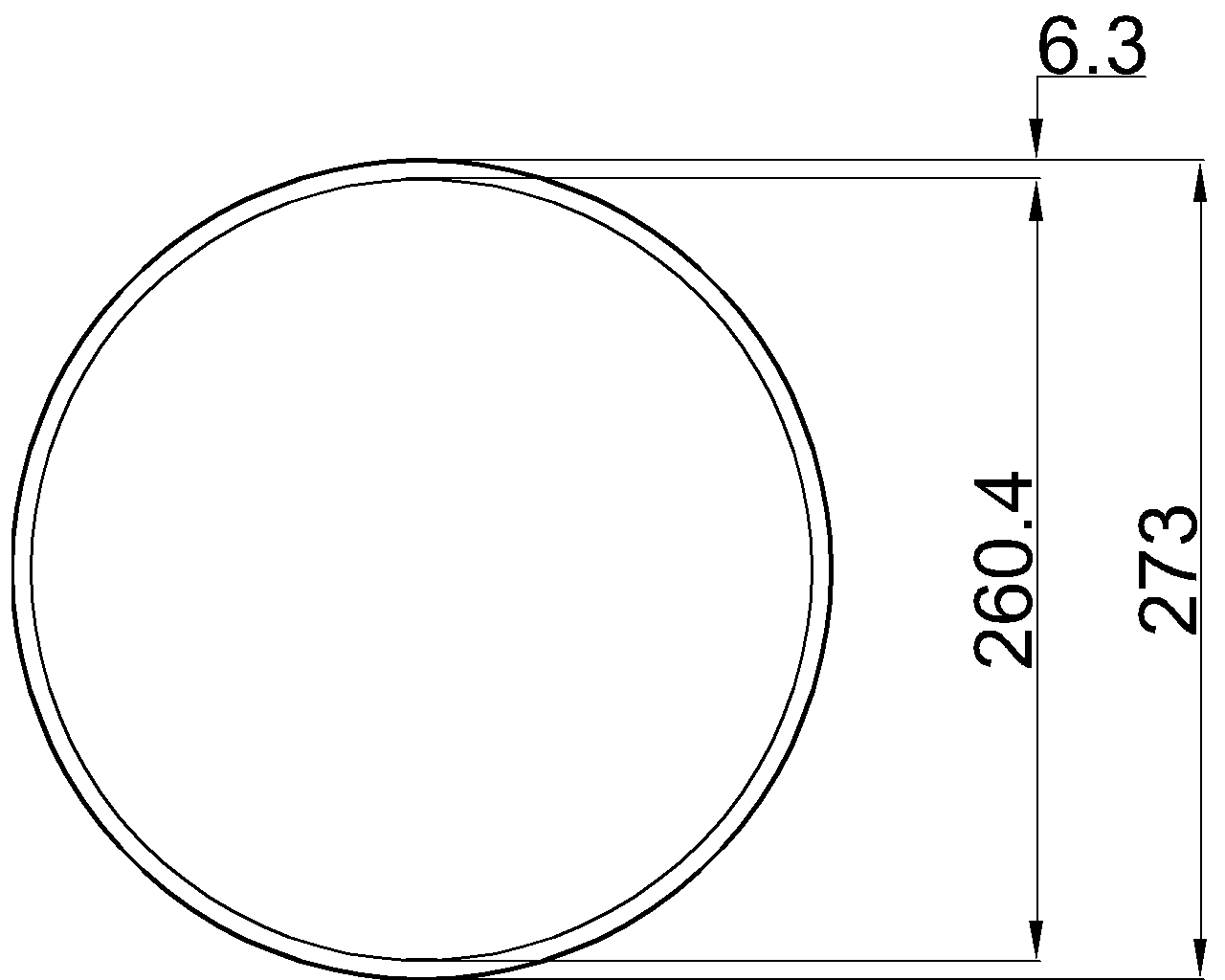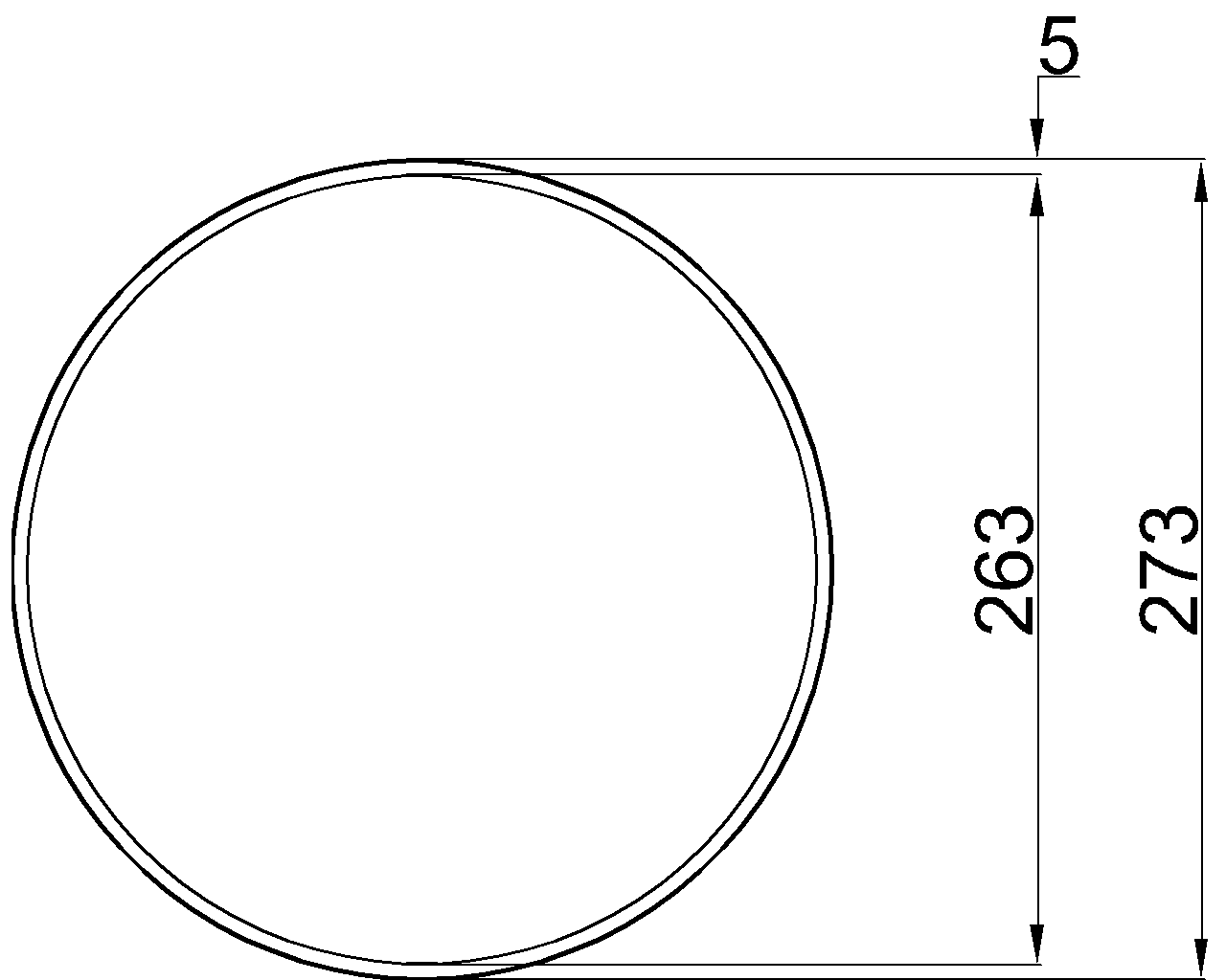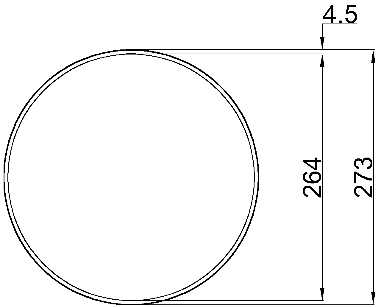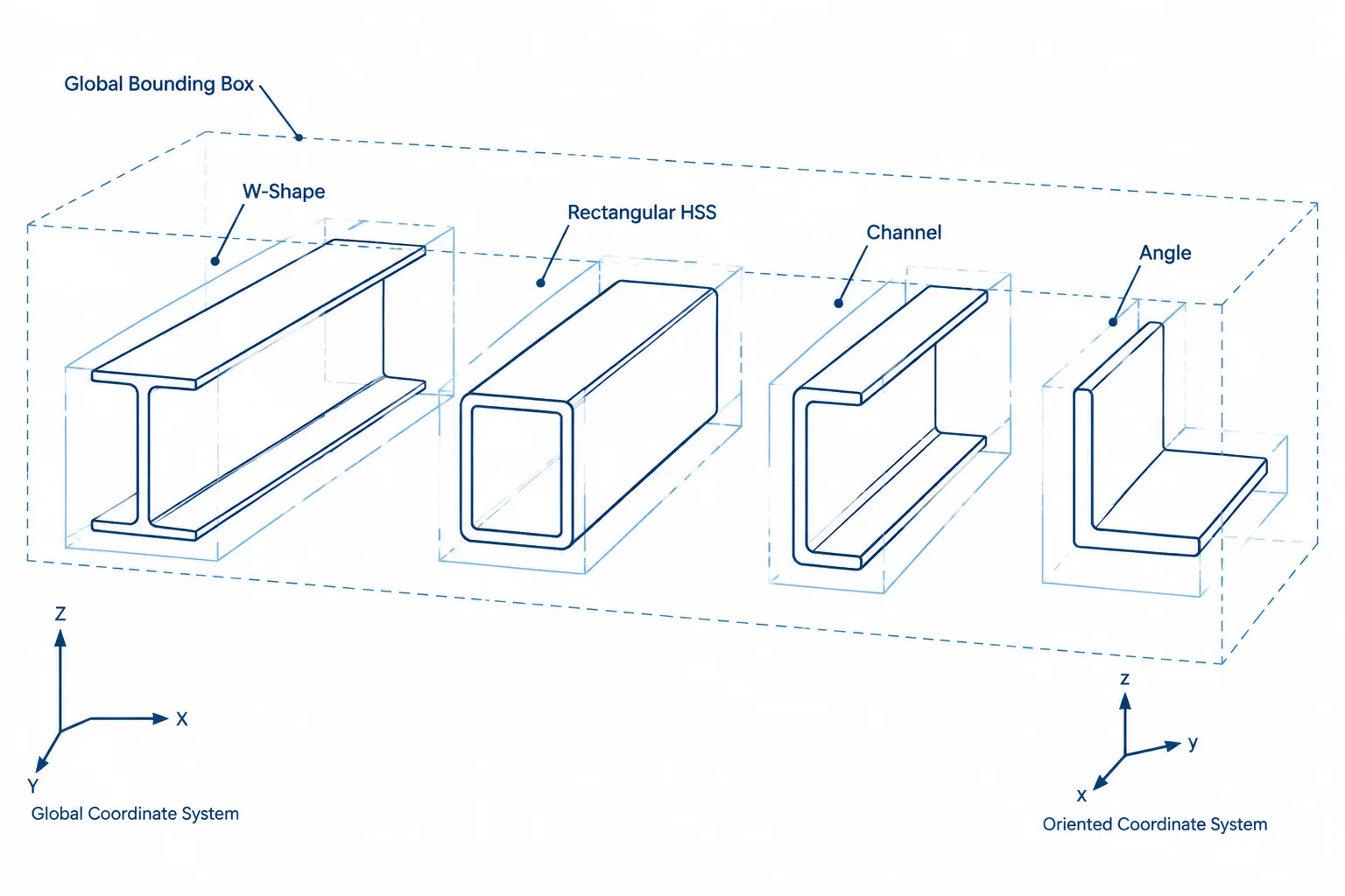
A structural steel bounding box is a geometric envelope that surrounds a shape, member, or assembly in a CAD model. It is useful for selection, preliminary clash detection, view creation, material handling studies, and automated drawing workflows. It is not, however, a substitute for the actual steel profile.
The difference matters because rolled shapes, HSS, channels, angles, tees, plates, and built-up members do not all occupy their envelopes in the same way. A bounding box may include large areas of empty space, and its reported dimensions can change when a member is rotated even though the steel shape itself has not changed.
What a structural steel bounding box represents
A bounding box records the outer limits of an object along selected coordinate directions. For a straight member, the box commonly represents overall width, overall depth, and member length. Depending on the software and workflow, those limits may be based on the member’s local axes, the global model axes, or a custom coordinate system.
That distinction produces two common types of envelope:
- Oriented bounding box: A box aligned with the member or section axes. It usually follows the member efficiently and remains meaningful when the member is skewed or sloped.
- Axis-aligned bounding box: A box aligned with the current global or drawing axes. Its overall extents generally increase or change when the object is rotated.
A bounding box may also be calculated for an entire assembly rather than one shape. In that case, plates, stiffeners, clip angles, bolts, weld representations, and other modeled items may determine the final envelope.
Shape dimensions and bounding-box dimensions are not interchangeable
Published steel dimensions describe the nominal or tabulated geometry of a specific shape. A CAD bounding box describes the extents of a particular modeled object in a particular orientation. The two may agree in a simple view, but they answer different questions.
| Information | What it describes | Typical use |
|---|---|---|
| Shape depth and width | Recognized dimensions of the steel profile | Identification, design reference, and detailing |
| Local bounding box | Envelope measured along member or section axes | Member placement, view generation, and local clearance |
| Global bounding box | Envelope measured along model axes | Model extents, broad clash searches, and spatial indexing |
| Assembly bounding box | Envelope around the main member and attached items | Shipping studies, erection planning, and drawing layout |
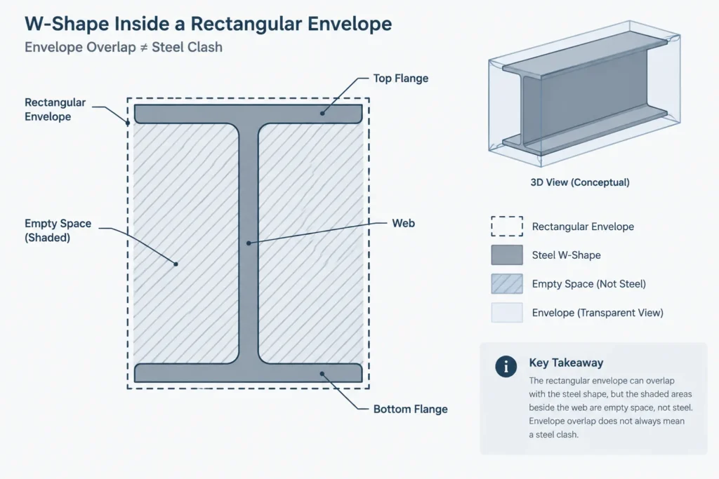
For example, an unrotated W-shape viewed square to its cross section may have an envelope corresponding closely to its overall flange width and section depth. The rectangular envelope still contains open areas on both sides of the web. A clash reported inside one of those areas may be a bounding-box overlap without any contact between actual steel surfaces.
How rotation changes reported extents
When a section rotates relative to the global axes, its axis-aligned envelope changes. This occurs with rotated columns, sloping braces, skewed framing, angles installed with a selected leg orientation, and members modeled in nonorthogonal structures.
For a rectangular local envelope with width b, depth d, and in-plane rotation θ, the global envelope can be described conceptually as:
Global width = |b cos θ| + |d sin θ|
Global depth = |b sin θ| + |d cos θ|
These expressions explain why a rotated member can appear wider in a property panel or automated report without any change to its steel designation. They describe the rotated rectangular envelope, not necessarily the exact occupied area of an asymmetric profile.
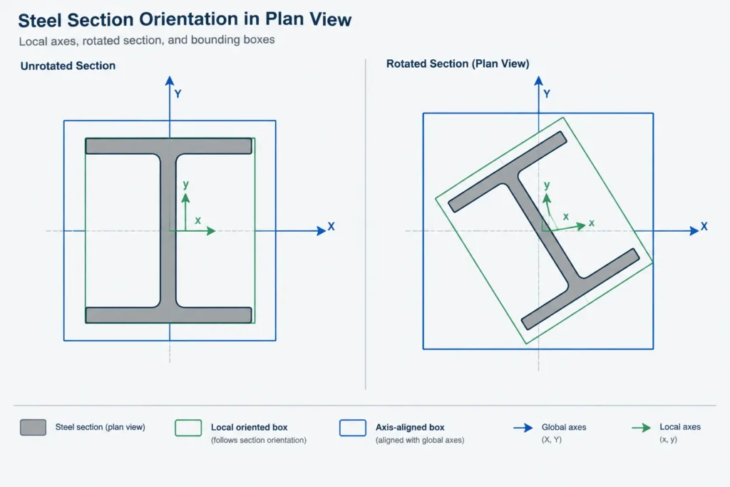
For angles, channels, and tees, rotating the local rectangular box may produce a conservative envelope because some box corners do not contain steel. Exact geometric extents should be calculated from the actual profile when the workflow requires close clearance evaluation.
How common steel shapes occupy their envelopes
W-shapes and other I-sections
An I-section reaches its maximum width at the flange edges and its maximum depth at the outer flange surfaces. Much of the bounding rectangle beside the web remains empty. A bounding-box clash near the web region therefore requires inspection of the actual solids or profile outlines.
HSS and pipe
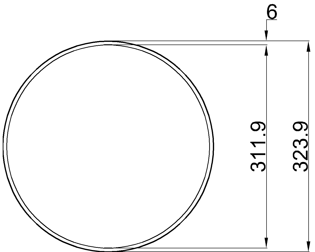
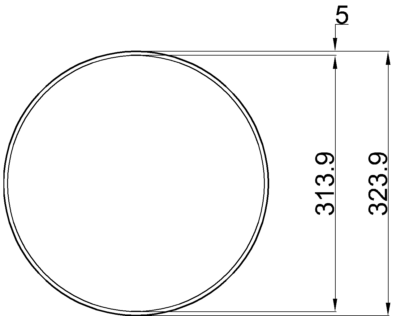
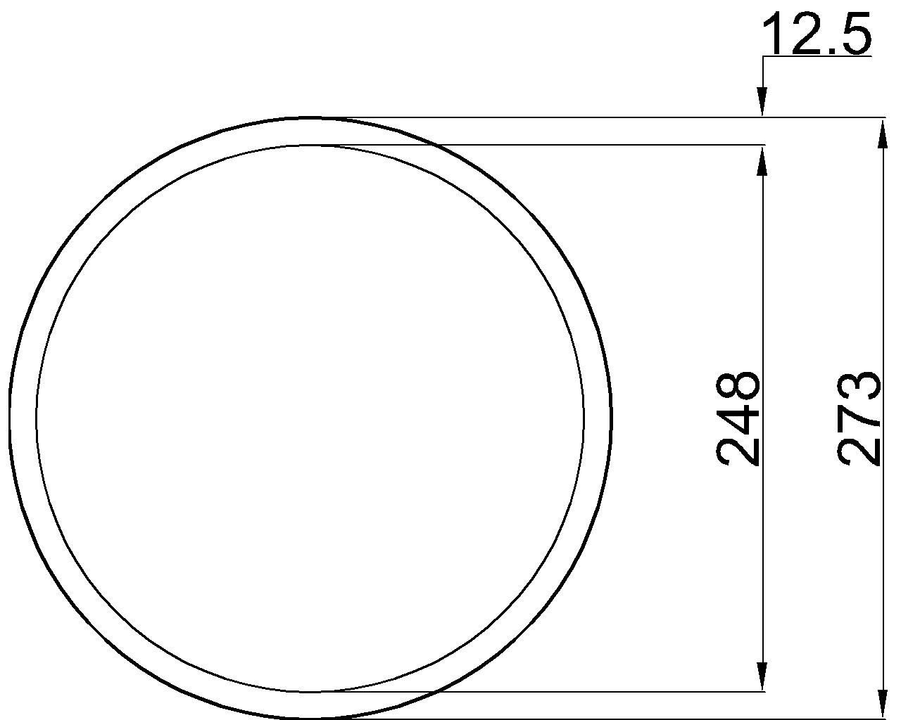
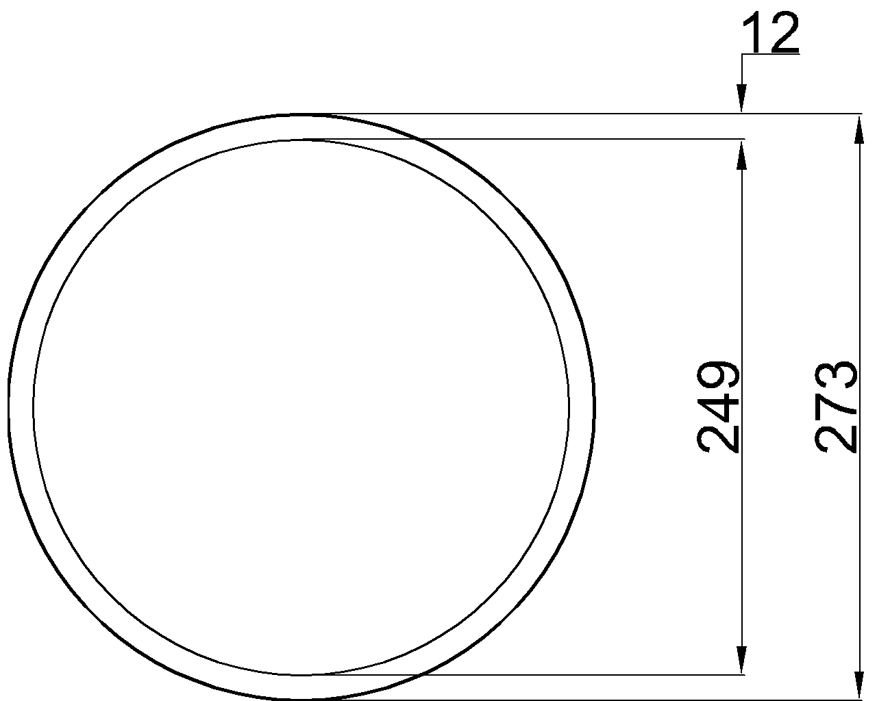
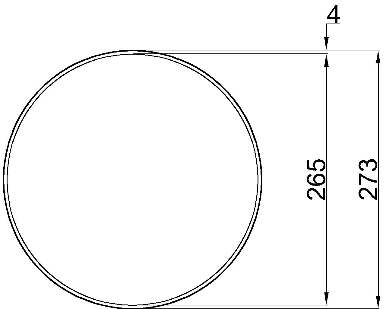
Rectangular and square HSS occupy their outer envelopes more completely than open shapes, although rounded corners remain relevant when an object approaches a corner. Circular HSS and pipe fit within a square envelope, leaving empty space near all four box corners. Bounding boxes are especially conservative for diagonal clearance checks around circular members.
Channels, angles, and structural tees
Open asymmetric shapes can leave substantial unused space inside their envelopes. Orientation is critical. Flipping a channel or changing which angle leg is vertical may leave the same local box dimensions while moving the actual steel to a different side of the work line.
A symmetric envelope can therefore hide an incorrect shape orientation. Drafters should inspect toes, heels, flange direction, and web location rather than relying only on the box.
Built-up members and assemblies
Cover plates, connection plates, stiffeners, splice material, and projecting bolts can govern an assembly envelope. Whether those items are included depends on what object was selected and how the model organizes parts and assemblies. The bounding box of the main member alone should not be assumed to represent fabrication or shipping clearance.
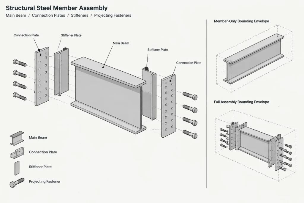
Bounding boxes in clash-detection workflows
Bounding boxes are effective as a fast first-stage filter. A system can identify objects whose envelopes overlap before performing a more demanding solid-to-solid comparison. This approach is often called broad-phase checking.
A reliable coordination process separates three results:
- No envelope overlap: The modeled objects do not clash under the current geometric assumptions.
- Envelope overlap only: The objects require a profile or solid check because the overlapping region may contain empty space.
- Confirmed geometry conflict: Actual surfaces, solids, fasteners, or required clearance zones interfere.
Clearance zones should also be modeled or checked separately from physical steel. Access for welding, bolting, coatings, inspection, fire protection, erection, and future maintenance is not represented by a tight geometric box around the member.
Common causes of misleading envelopes
- Unexpected coordinate system: The reported box may follow global axes when the user expects member-local dimensions.
- Hidden or nested objects: Construction geometry, connection components, or imported entities may enlarge the selected extents.
- Simplified profiles: A generic rectangular solid may have been used instead of the actual steel section.
- Curved or cambered members: A straight chord-based envelope may not describe the full swept geometry.
- End cuts and copes: A box based on the original member may differ from one recalculated after fabrication features are applied.
- Linework thickness or annotations: In a two-dimensional drawing, text, leaders, or symbolic lines may be included in selection extents even though they are not steel.
- Unit or scale errors: Imported content can produce an obviously oversized or undersized envelope when source units are interpreted incorrectly.
A practical CAD checking procedure
- Confirm the object type. Determine whether the selection is a profile, member solid, block, external reference, part, or complete assembly.
- Identify the coordinate basis. Check whether the displayed dimensions follow global axes, local member axes, or a temporary working coordinate system.
- Verify the steel designation. Compare the modeled section with a trusted shape reference rather than treating envelope dimensions as identification data.
- Inspect section orientation. Confirm flange, web, leg, toe, and heel positions in a cross-sectional view.
- Review attached material. Decide whether plates, fasteners, and other projections must be included for the task.
- Use actual geometry for close checks. Replace broad envelope comparisons with profile, surface, or solid interference checks where clearance is limited.
- Document assumptions. Note whether the result represents nominal geometry, modeled geometry, an assembly, or an added clearance zone.
Using bounding boxes without losing dimensional control
Bounding boxes are valuable automation tools, but they should remain secondary to verified section geometry. Use them to find objects, organize views, estimate occupied regions, and identify possible conflicts. Use shape tables, controlled CAD profiles, and actual model geometry to establish dimensions and confirm fit.
When an envelope appears inconsistent with a shape designation, first check rotation, coordinate systems, included components, and imported scaling. A changing global envelope does not necessarily indicate that the member size changed. It may simply show that the same steel object is being measured in a different direction.