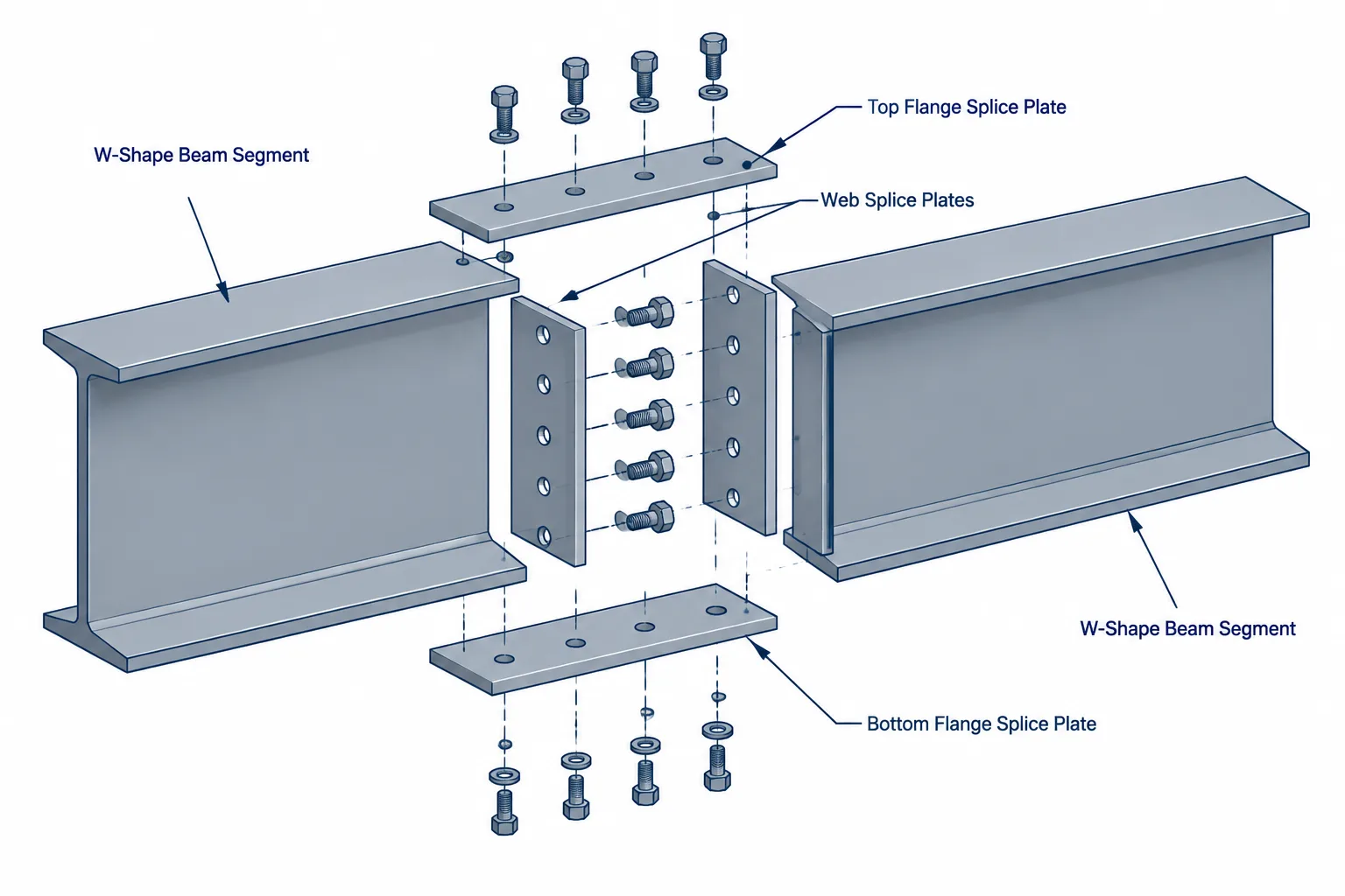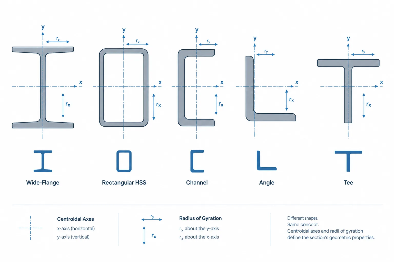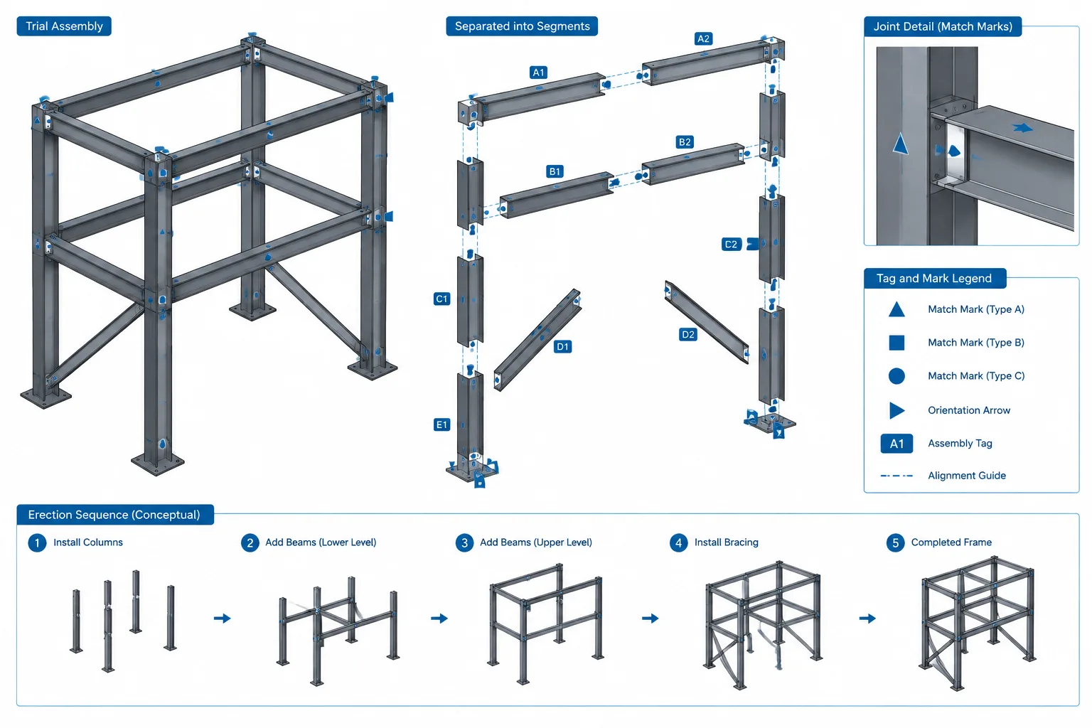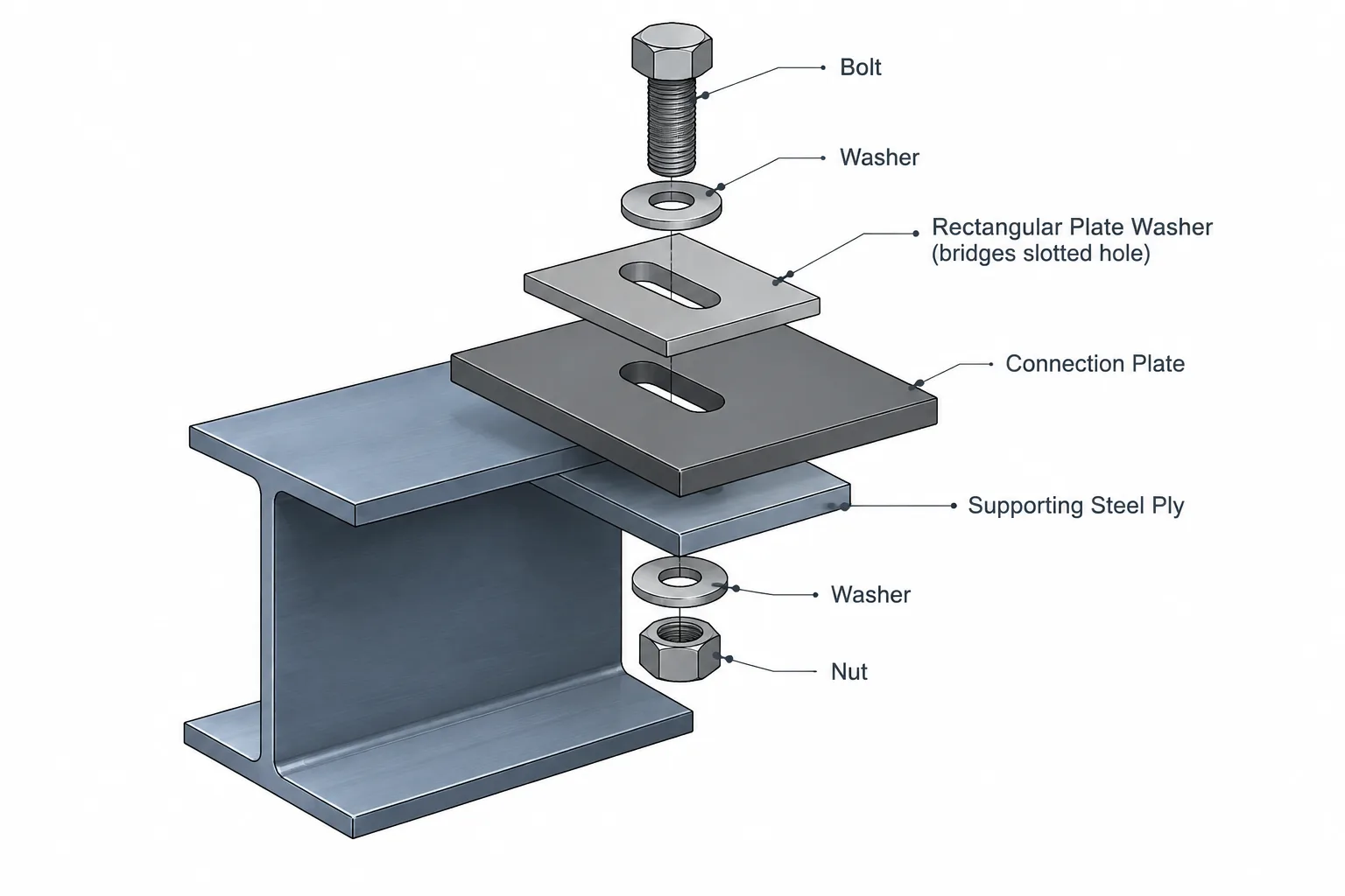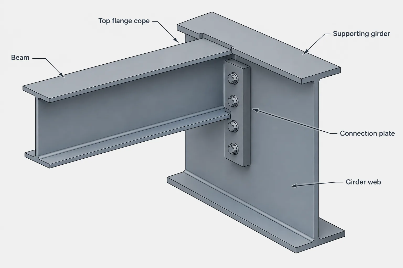
Steel beam ends often require material to be removed so that framing members, plates, bolts, welds, or adjacent shapes can fit together. The resulting cut may be called a cope, notch, blockout, flange cut, or another project-specific term. Although these words are sometimes used loosely, they do not always communicate the same geometry.
Reliable steel beam cope detailing requires more than drawing a rectangular cut at the end of a member. The detail must establish where the cut begins, which surfaces control it, how the inside corner is formed, and whether enough material remains for the intended connection. It must also agree with the structural design, fabrication method, erection sequence, and referenced member orientation.
Cope, notch, and blockout terminology
Terminology varies among engineering offices, fabricators, drawing conventions, and software systems. A drawing should therefore define the actual cut rather than relying on a label alone.
| Term | Typical use | Detailing concern |
|---|---|---|
| Beam cope | Removal of a flange and an adjacent portion of the web near a beam end, commonly to clear supporting steel | Cope length, cope depth, remaining web, corner geometry, and connection-hole location |
| Notch | A general localized removal from an edge, flange, web, plate, or HSS wall | The word alone may not define the cut boundaries or fabrication process |
| Blockout | A broader term for an omitted or removed region needed for clearance or fit | Its limits should be dimensioned from stable part datums |
| Flange cut | Partial or complete removal of flange material without necessarily using conventional cope geometry | The transition into the remaining flange and web must be shown clearly |
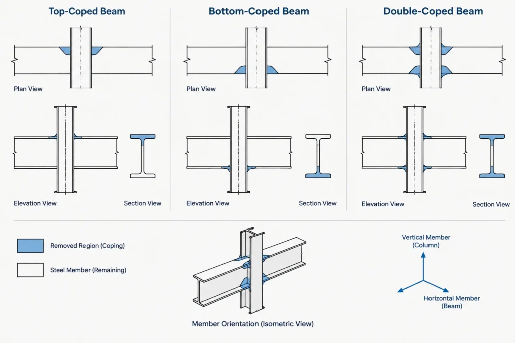
A top cope usually removes part of the top flange and the web directly below it. A bottom cope affects the corresponding lower region. A double-coped beam has cuts at both flanges near the same end. These descriptions identify the general condition, but they do not establish the required dimensions.
Why beam ends are coped
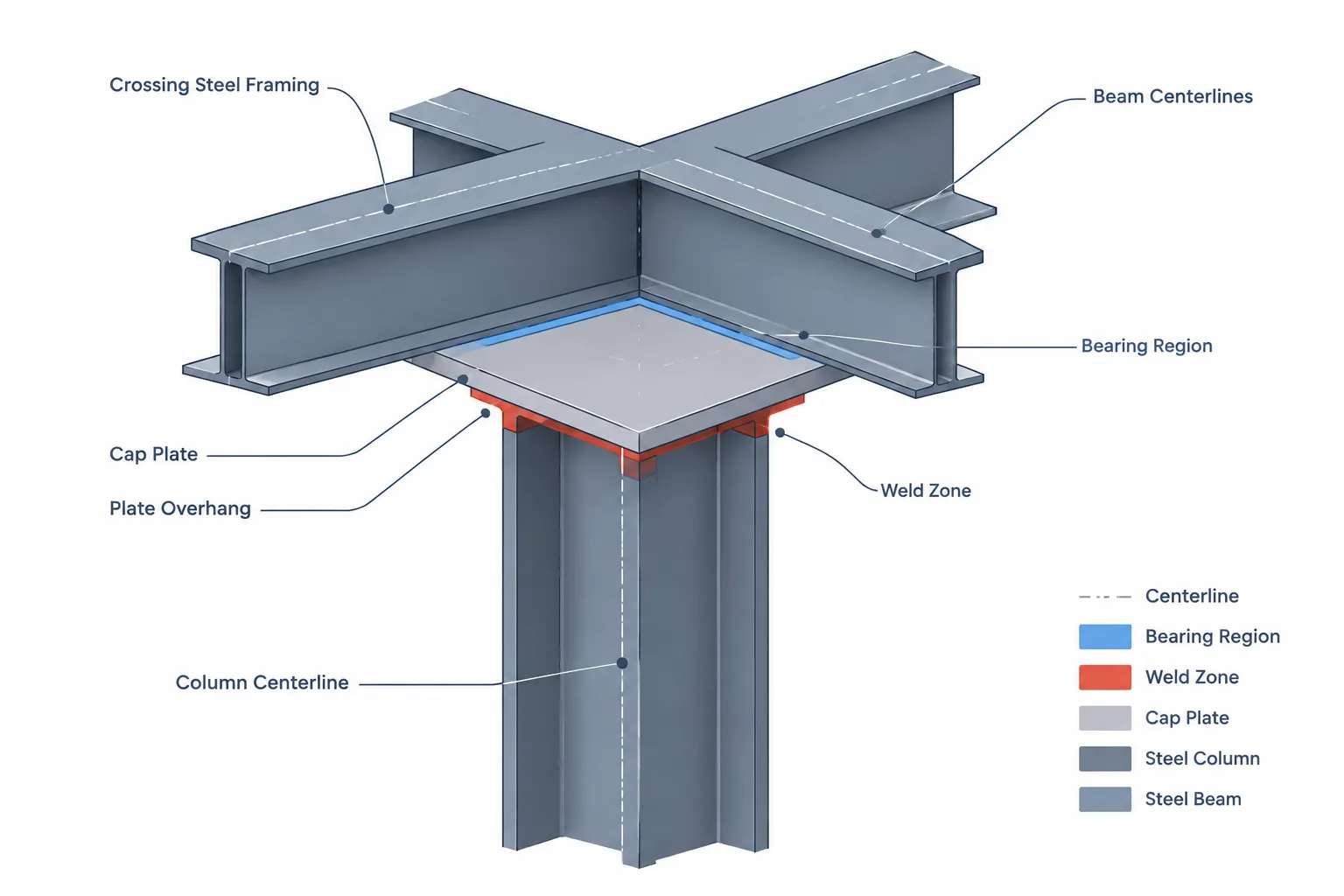
A common framing condition places the top of a supported beam near the top of a supporting beam or girder. The supported beam flange may interfere with the supporting member’s flange before the supported beam web reaches its intended connection plane. Removing a portion of the supported beam flange and web can provide the necessary clearance while leaving a web region available for a shear connection.
Copes may also be used around seats, plates, stiffeners, projecting connection material, intersecting framing, or architectural constraints. In every case, the cut should correspond to an identified physical conflict. A generic cope copied from another beam may provide too little clearance, remove unnecessary material, or conflict with the connection design.
The dimensions that define a cope
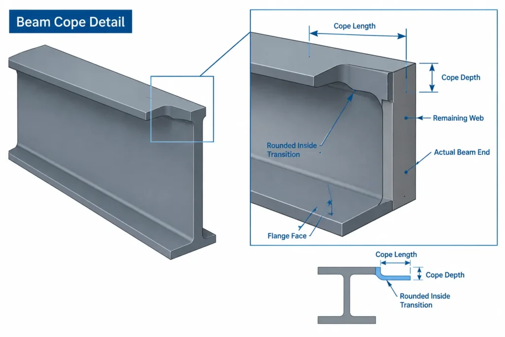
Cope length
Cope length locates the inside boundary of the cut relative to the beam end or another stated datum. The detail should make clear whether the length is measured from the theoretical member end, the actual cut end, a connection plane, or a work point. These locations can differ when the beam has an end setback, skewed end, or sloping cut.
Cope depth
Cope depth establishes how far the cut extends from a referenced beam surface. It may be controlled from the outside face of a flange, the top-of-steel line, the bottom-of-steel line, or another clearly identified edge. Dimensioning only to a nominal member depth can be ambiguous because the fabricator needs the location of the actual cut boundary.
Remaining web geometry
The portion of web left after coping is important to both connection layout and structural behavior. The detail should allow the reviewer to identify the remaining web depth, the proximity of holes to cut edges, and the relationship between the cope and any connection plate, angles, welds, or seat.
Inside corner and transition
An idealized CAD rectangle creates a sharp re-entrant corner. The fabricated condition may instead include a drilled termination, rounded transition, saw-cut termination, thermal-cut radius, or another shop-specific profile. The selected geometry can affect fit, stress concentration, fabrication sequence, and inspection. Do not assume that a zero-radius CAD corner adequately defines the required condition.
If the corner treatment is structurally significant, the engineer’s detail or approved fabrication criteria should govern it. A drafter should not invent a corner radius or cut process merely to make the model look realistic.
Choose datums that survive member changes
Good cope dimensions originate from surfaces and planes that control fit. Depending on the connection, useful datums may include:
- The actual beam end or connection face
- Top of steel or bottom of steel
- The face of the supporting member
- The supported beam web centerline
- A flange face rather than a nominal depth line
- A connection plate edge or bolt-group work line
Dimensions based on unstable references can fail when a member size changes. For example, locating a hole group from the bottom of a cope may unintentionally move the holes if the cope depth is revised for clearance. Where practical, connection holes and cope geometry should be tied to the datums that independently control each feature.
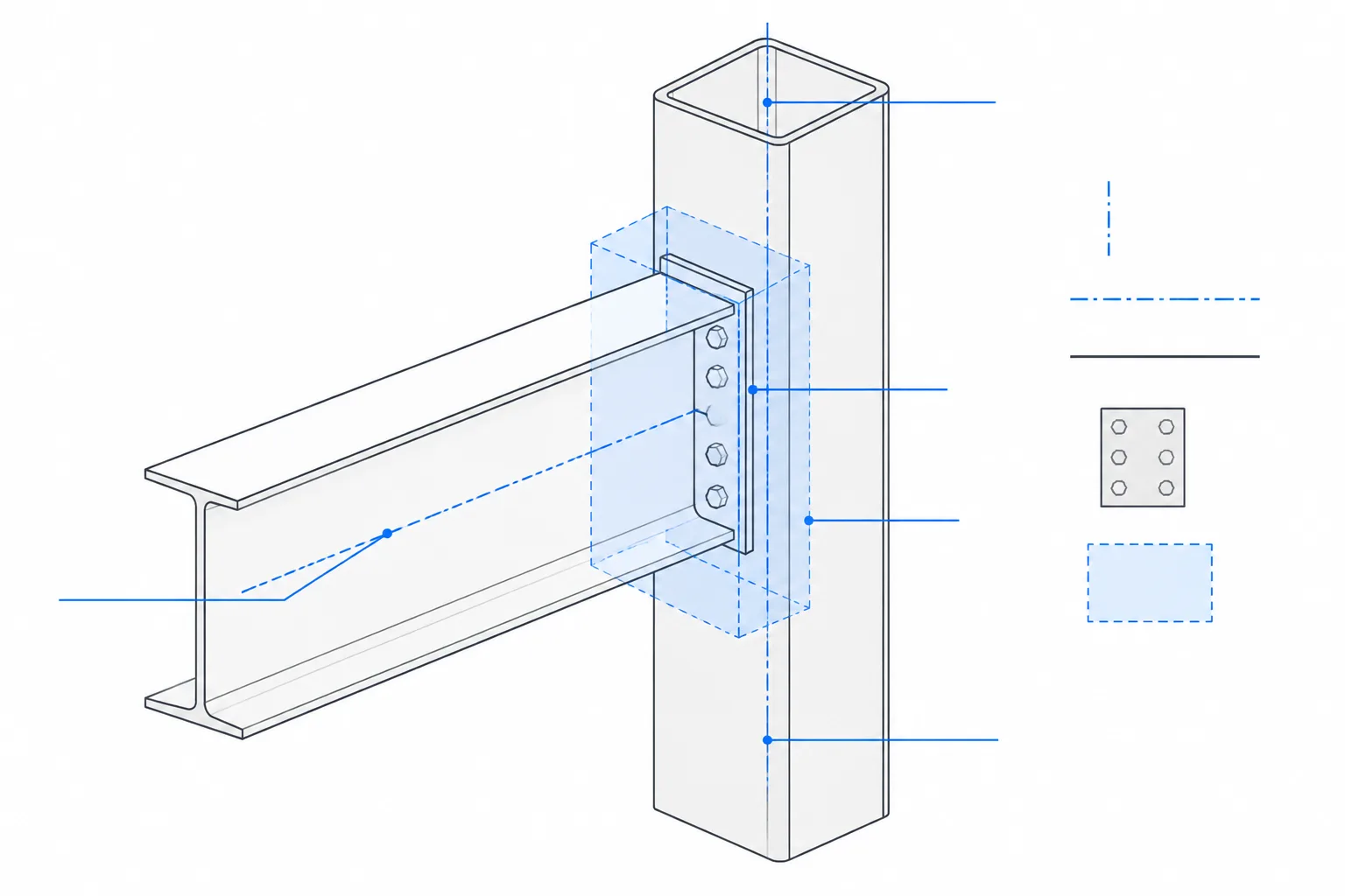
Connection coordination at a coped end
A cope and its connection must be checked as one assembly. The cut changes the available web region and may alter the paths through which the end reaction reaches the connection.
Coordination checks commonly include:
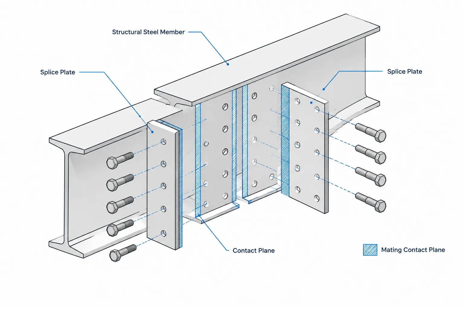
- Whether the connection plate, angles, or welds fit within the remaining web
- Whether bolt holes maintain the required relationship to the beam end and coped edges
- Whether bolt heads, nuts, washers, and installation tools clear nearby flanges
- Whether the supported beam can be erected without binding against the supporting member
- Whether weld access and termination remain practical
- Whether a skew, slope, camber condition, or member rotation changes the true clearance
- Whether the cut removes material assumed by the connection or member design
A connection that fits in a flat elevation may still clash in three dimensions. This is especially important at skewed framing, sloped beams, deep supporting flanges, and connections with plates on both sides of a web.
Structural effects that require design review
Coping reduces the beam’s original cross-section near its end. Depending on the configuration, the affected region may require checks involving shear, local bending, stability of the remaining web, stress concentration, connection limit states, and the interaction of the cut with bolt holes or welds. A deep or long cope is not simply a larger version of a routine clearance cut.
The detailer can identify geometry and flag unusual conditions, but should not infer structural acceptability from appearance or from a similar detail. Cope dimensions, reinforcement, corner treatment, and connection arrangement should follow the project design information and approved coordination process.
CAD modeling workflow
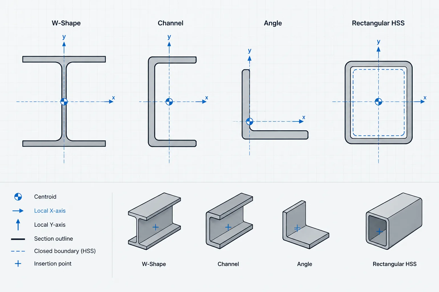
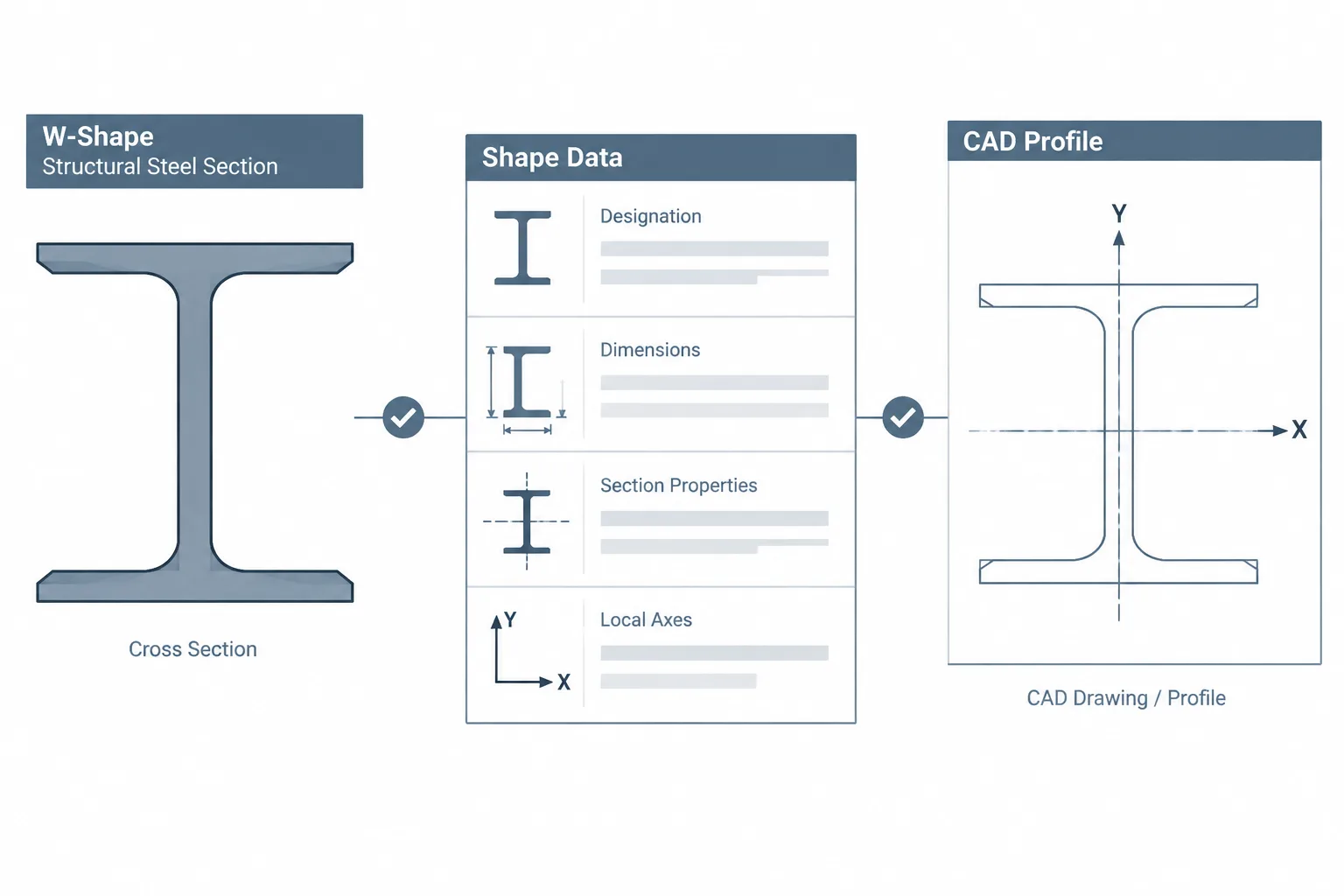
For a dependable model or shop-detail workflow, begin with the verified steel shape rather than a symbolic beam envelope. Establish the member axis, section orientation, actual end plane, and supporting-steel geometry before creating the cut.
-
Model the interference. Place the supported and supporting members using their controlling work points and elevations.
-
Identify the required clearance zone. Include connection parts and installation space, not only the rolled-shape outlines.
-
Create the cope from explicit dimensions. Avoid dragging an unconstrained cut until it appears to fit.
-
Apply the intended corner representation. Distinguish a simplified model corner from a fabrication-controlling profile.
-
Add the connection layout. Locate holes, plates, angles, and weld boundaries from their proper datums.
-
Review in multiple views. Check elevation, plan, section, and a three-dimensional view where the geometry is not orthogonal.
-
Transfer controlling information to drawings. The shop drawing should not depend on measuring the model to discover cope dimensions.
Common detailing failures
- Ambiguous end reference: The cope is dimensioned from a work point, but the beam has a separate actual cut end.
- Nominal geometry used for fit: Simplified flange and fillet geometry hides a clash with supporting steel or a connection plate.
- Holes tied to the cope: A clearance revision unintentionally relocates the connection bolt group.
- Sharp CAD corner treated as fabrication intent: No corner termination or cut method is communicated.
- Top and bottom confused: Member rotation, mirrored views, or inconsistent piece-mark orientation places the cope on the wrong flange.
- Only one view checked: A skewed or sloped condition fits in elevation but interferes in plan or section.
- Copied cope reused without review: A cut developed for one supporting shape is applied to another with different geometry.
What a clear shop detail should communicate
A complete beam-end detail should show the member orientation, cut location, cope length and depth, end reference, corner treatment where required, and the relationship of the cut to holes and connection parts. Sections or enlarged details are useful when the main view cannot clearly distinguish flange removal from web removal.
Notes should supplement visible geometry, not replace it. A note reading “cope as required” may identify an intent but does not provide enough information for controlled fabrication unless the limits are defined elsewhere. The final detail should let fabrication, checking, and erection teams understand the same end condition without relying on assumptions.
Steel beam cope detailing is therefore a coordination task as much as a drawing task. Clear terminology, stable datums, verified shape geometry, and connection-aware checks help turn a simple-looking cut into a buildable and reviewable beam end.