The distinction between a shop connection and a field connection affects much more than where a bolt is tightened or a weld is deposited. It influences assembly limits, piece marks, shipping, erection sequencing, drawing organization, inspection access, and responsibility among project participants.
For drafters and detailers, the key question is not simply whether a connection can be made in the shop. The connection must also fit the intended fabrication and erection process. A perfectly modeled connection can still create problems if it joins members that must ship separately, blocks access to another fastener, or assumes that field geometry will match the model without adjustment.
What Shop and Field Mean on Steel Drawings
A shop connection is completed as part of fabrication before the affected assembly is shipped. A field connection is completed at the construction site during erection or subsequent field work.
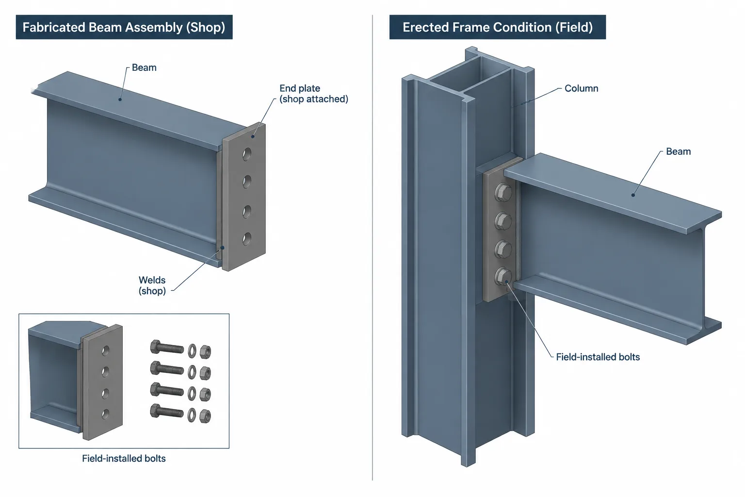
These terms describe the planned stage of work, not merely the physical position of the connection. A plate located at the end of a beam may be shop welded to that beam, while the same plate is field bolted to a column. One connection region can therefore contain both shop and field operations.
The distinction should remain consistent across:
- Design drawings and connection notes
- Fabrication and assembly drawings
- Erection plans and elevations
- Three-dimensional steel models
- Bolt, plate, and material lists
- Weld information and inspection documents
- Revision clouds and change records
Typical Shop and Field Operations
| Operation | Common stage | Coordination concern |
|---|---|---|
| Welding an end plate, shear plate, stiffener, or clip angle to a member | Often shop | Assembly size, weld access, distortion, and shipping clearance |
| Bolting a beam assembly to a column or supporting member | Often field | Erection access, fit-up, temporary stability, and bolt installation clearance |
| Splicing separately shipped members | Often field | Alignment, support during erection, hole matching, and splice access |
| Attaching small components to a shipping member | Often shop | Whether projections can survive handling and transportation |
| Installing loose plates or connection angles | Often field | Part identification, orientation, handling, and risk of misplaced material |
| Making closure or continuity welds | Project dependent | Field position, weather protection, access, inspection, and sequence |
These are common patterns, not universal rules. The contract documents, connection design, fabricator preferences, erection plan, transportation limits, and project specifications determine the actual division of work.
Why Shop Welding Is Often Preferred
Shop welding is frequently favored because the fabricator can control member position, access, equipment, consumables, and working conditions more effectively than is usually possible in the field. Assemblies can be rotated to improve welding position, and fit-up can be checked before shipment.
That preference does not mean every welded connection should become a shop connection. A welded joint between two large framing members may have to remain a field operation because the completed assembly cannot be transported or erected as one piece. A shop-attached plate can also create an awkward projection that interferes with loading, unloading, or adjacent steel.
When assigning a shop weld, the detailer should verify:
- Which member owns the attached plate or component
- Whether all welds are accessible in the planned assembly position
- Whether welding can distort critical connection geometry
- Whether the finished assembly remains practical to ship and handle
- Whether attached components conflict with lifting points or erection access
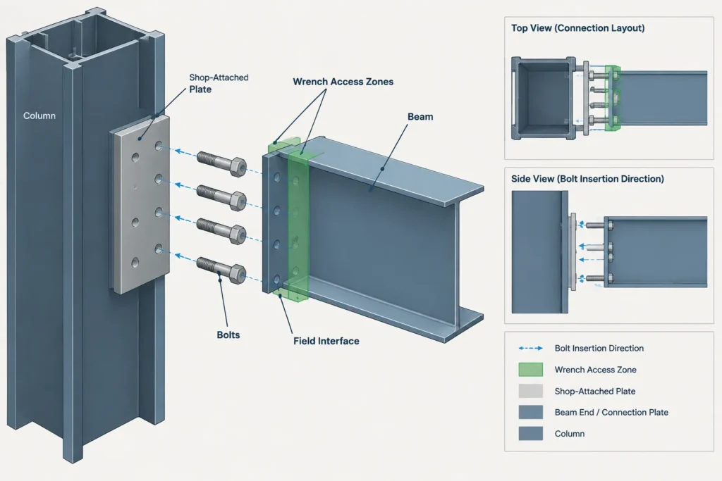
- Whether the shop operation leaves adequate access for field bolts
Why Bolted Joints Are Common in the Field
Bolted field joints allow separately fabricated members to be brought together during erection. They can accommodate the practical sequence of setting columns, beams, braces, and other assemblies without requiring extensive field welding.
A bolted connection still requires more coordination than placing holes in two modeled parts. The erector needs a workable path to insert the bolt and enough room to place and operate the required installation equipment. Nearby flanges, HSS walls, stiffeners, deck edges, concrete, cladding supports, or other bolts can restrict access.
Detailers should examine the connection from both sides and through the likely erection sequence. A bolt that appears accessible in an isolated section may become inaccessible after another beam, brace, or plate is installed.
Shop Bolts and Field Bolts Are Both Possible
Bolts are not automatically field items. A bolted subassembly may be completed in the shop when that arrangement supports fabrication, coating, transportation, or later erection. Conversely, some components that are normally welded in the shop may require field attachment on a particular project.
The drawing set should identify the intended condition rather than relying on an assumed rule that all welds are shop work and all bolts are field work.
Piece Marks and Assembly Ownership
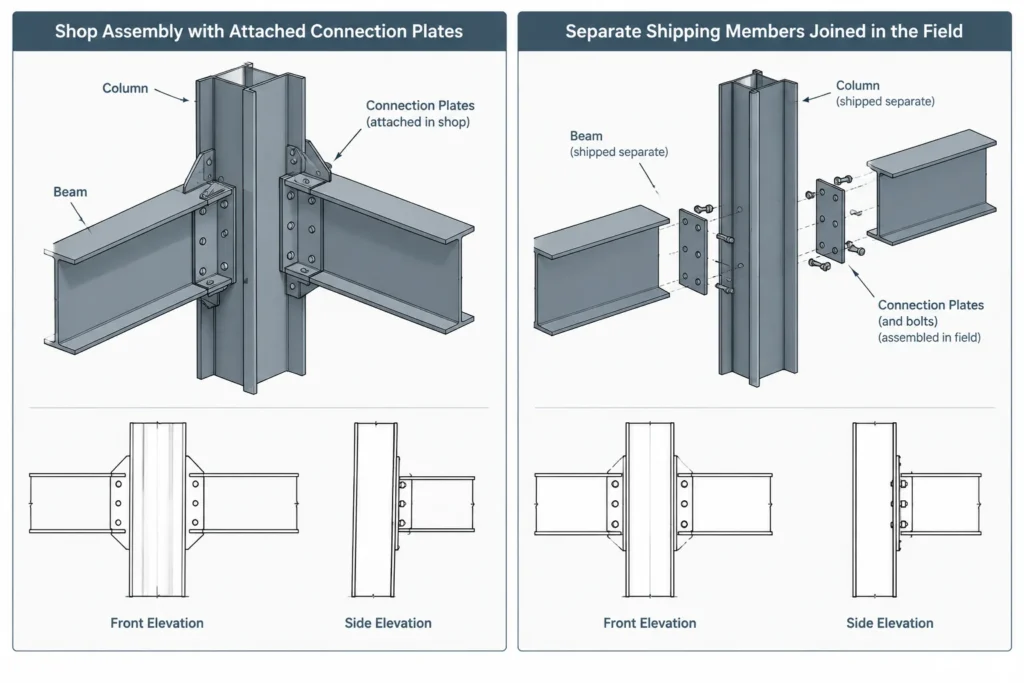
Shop attachments generally become part of a marked shipping assembly. For example, a beam may carry shop-attached plates, angles, stiffeners, or seats under one assembly mark. Loose components installed during erection may receive separate part identification and must be shown clearly on erection or installation information.
Assembly ownership matters because the same connection plate cannot be casually assigned to both adjoining members. The detailer should establish which member receives the plate in the shop and which interface remains open for field connection.
A useful review is to mentally separate the model into shipping pieces. If disconnecting the field joints does not produce practical, identifiable assemblies, the shop-versus-field assignment may need revision.
Drawing Conventions That Need Explicit Control
Structural drawings often use notes, linework, bolt indications, weld symbols, and erection diagrams to distinguish shop and field work. A field weld may be identified through the applicable weld-symbol convention, while shop welds are generally understood from the fabrication drawing context. However, office and project practices vary, so the drawing legend and contract requirements must govern.
A complete detail should make the following clear:
- Which parts are shop attached
- Which parts ship loose
- Which bolts are installed in the field
- Which welds are made in the field
- Which member or assembly owns each connection component
- Whether a view shows the fabricated condition or the completed erected condition
- How hidden plates or inaccessible connection faces are oriented
Avoid depending on color alone. Printed drawings, exported files, and downstream model views may not preserve the same color display. Text, symbols, view labels, and consistent assembly logic provide more durable communication.
Erection Sequence and Temporary Conditions
The completed structure may be stable even though an individual erection stage is not. A connection detail must therefore be considered in relation to the planned sequence, including how a member is initially supported, aligned, and secured.
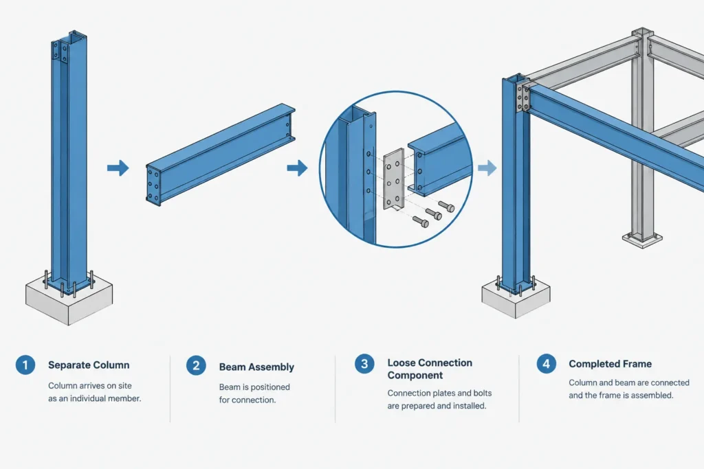
Detailers should not invent temporary bracing, lifting procedures, or erection methods. Those items require coordination with the responsible project parties. Drawings should nevertheless avoid unintentionally depicting an impossible sequence, such as requiring access through a member that must already be installed or calling for a closure weld where the joint cannot be reached.
Questions about temporary support, initial bolt installation, field fit-up, or member stability should be raised rather than resolved through an undocumented drafting assumption.
Modeling and CAD Workflow
In a steel model, connection components should be associated with the correct assembly and given a clear shop or field status where the workflow supports it. Before issuing drawings, isolate each shipping assembly and compare it with the erection model.
A practical review sequence is:
- Hide adjoining members and inspect the fabricated shipping piece.
- Confirm that all shop attachments remain with the intended assembly.
- Restore adjacent members and inspect each field interface.
- Check bolt insertion, tightening, welding, and inspection access.
- Review projections that may affect shipping or handling.
- Compare the model with piece marks, details, and erection views.
- Verify that revisions changed every affected representation and list.
Do not treat the model as self-explanatory. A correct model can produce ambiguous drawings if views do not reveal which components are attached, loose, or installed later.
Common Coordination Errors
- Assigning a plate to the wrong member: The plate appears in the connection model but ships with an unintended assembly.
- Using an inaccessible field weld: The joint is visible in elevation but blocked by surrounding steel in three dimensions.
- Ignoring bolt installation direction: Space exists around the hole, but not along the bolt path or at the tool side.
- Creating an oversized shipping assembly: Converting a field joint to shop work joins members that were intended to ship separately.
- Leaving loose material unidentified: A plate or angle is shown near the connection without a clear mark or installation location.
- Mixing fabricated and erected conditions: A detail shows components in their final position without indicating which pieces are shop attached.
- Updating only one drawing: A connection revision changes the detail but not the assembly sheet, erection view, model status, or material list.
A Final Review Checklist
- Can the shop assembly be fabricated, handled, coated if required, and transported as shown?
- Can the field connection be reached after surrounding members are installed?
- Are bolt insertion and installation-tool clearances available?
- Are field weld locations accessible and clearly identified?
- Does every attached or loose component have unambiguous ownership?
- Do piece marks and erection views match the shop-versus-field division?
- Has the intended sequence been coordinated without assuming an unapproved erection method?
- Are project-specific symbols, notes, and responsibilities applied consistently?
Clear shop and field connection information links design intent to fabrication and erection reality. The most reliable details do not merely show the final geometry; they communicate how separate pieces become a completed steel frame while preserving access, identification, and a workable construction sequence.