A shear tab is a relatively simple connection component, but its geometry depends on several references that are easy to confuse. The support face, beam work point, beam end, plate edge, bolt line, and web centerplane are related, yet they are not interchangeable datums.
Reliable shear tab connection detailing begins by identifying which dimensions control fabrication and which dimensions merely describe the resulting assembly. It also requires coordination among the beam end, connection plate, bolts, support, welds, and any beam cope. A connection that looks reasonable in a schematic model can still contain fit-up conflicts when these elements are developed at fabrication-level accuracy.
What Is a Shear Tab Connection?
A shear tab, also called a single-plate shear connection, commonly consists of a plate attached to a supporting member and bolted to the web of a supported beam. A typical fabrication sequence may place the plate on the supporting member in the shop and connect the beam to it in the field. The actual erection and fabrication sequence must be confirmed from the project documents and connection design.
The term describes a connection arrangement, not one universal detail. Plate proportions, bolt layout, weld configuration, beam-end geometry, and supporting-member conditions can vary. A plate connected to a column flange does not necessarily use the same detailing geometry as one connected to a column web, girder web, HSS face, or embedded support.
Primary Datums That Control the Detail
Before placing the plate or holes in CAD, establish the controlling references. The most important datums generally include the following.
Support face
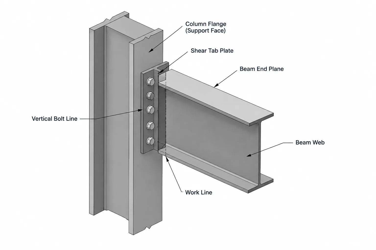
The support face is the physical surface from which plate projection and beam-end clearance may be evaluated. On a column flange, it is the outside flange face. On a girder web or HSS wall, the relevant support surface must be identified in the connection detail.
A support centerline is not the same as a support face. If a framing plan locates a beam to a column grid or member centerline, the actual face position must be developed from the supporting section geometry and orientation.
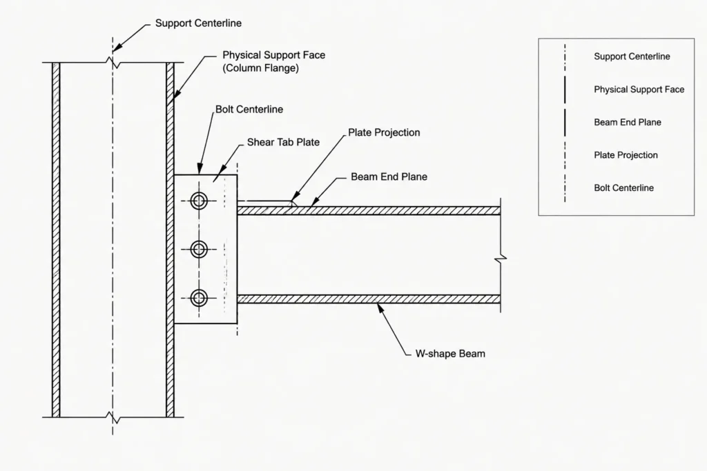
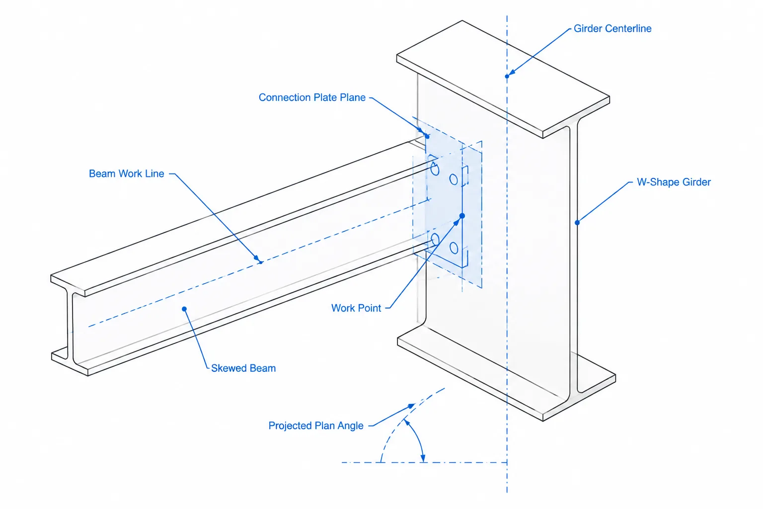
Beam work line and work point
The beam work line usually represents the member’s layout axis. Its intersection with a column grid, girder line, or another member axis may establish a work point. This reference is useful for locating members in the overall structure, but it does not automatically define the physical beam-end plane.
The beam may stop short of the support face. That setback must be represented explicitly rather than hidden inside a connection block or assumed from a schematic framing line.
Beam end plane
The beam end plane controls the actual cut end of the supported member. It may be square to the beam axis or affected by skew, slope, or another project-specific condition. The distance between this plane and the support face influences erection clearance and the relationship between the web holes and the plate.
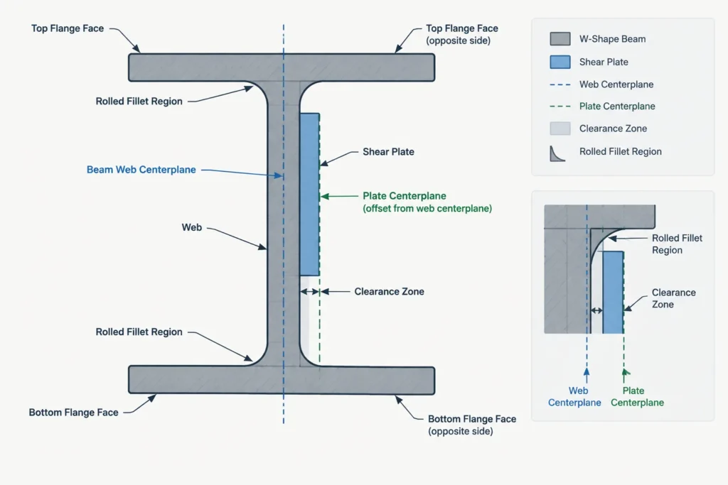
Beam web centerplane
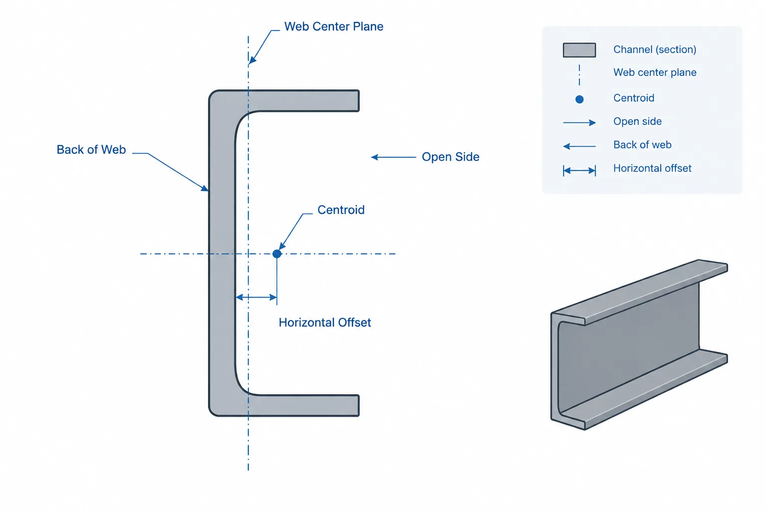
The web centerplane is a useful reference for locating the beam and checking which side of the web receives the plate. Because a shear tab normally lies against one side of the beam web, the plate centerplane is offset from the web centerplane rather than coincident with it.
This offset matters in a three-dimensional model. Centering the plate on the beam axis can produce a visually subtle but physically incorrect connection.
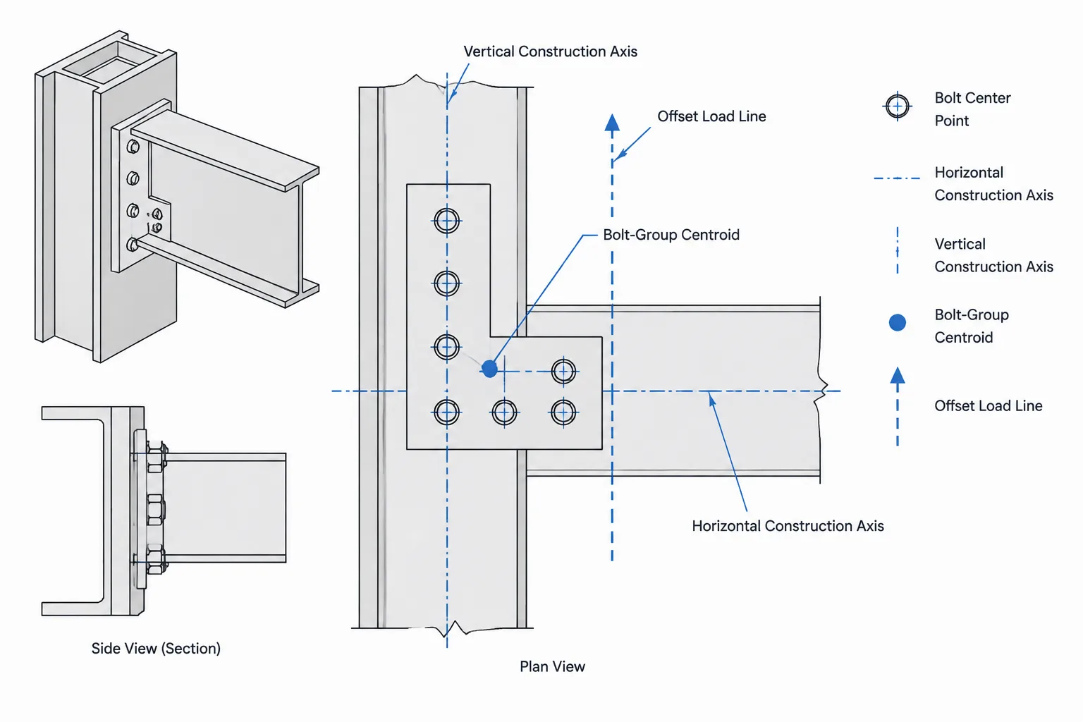
Bolt line and hole centers
The bolt line is established by hole centers, not by the visible edges of bolt heads, nuts, or washers. Its location should be traceable to a clear datum such as the beam end, support face, or plate edge, according to the approved connection information.
If multiple vertical bolt rows are present, distinguish the individual row locations from the centroid of the entire bolt group. The bolt-group centroid may be important to connection behavior, but it is not a substitute for fabrication dimensions to each required hole line.
How the Beam Setback and Plate Projection Interact
Beam setback and plate projection describe different geometry. Beam setback locates the member end relative to the support. Plate projection describes how far the plate extends from its attachment region toward the beam.
They must be coordinated, but one should not be casually derived from the other. The plate needs sufficient reach for the specified hole arrangement, while the beam end needs appropriate clearance from the support, plate weld region, and other obstructions. The final relationship comes from the connection design and project detailing requirements.
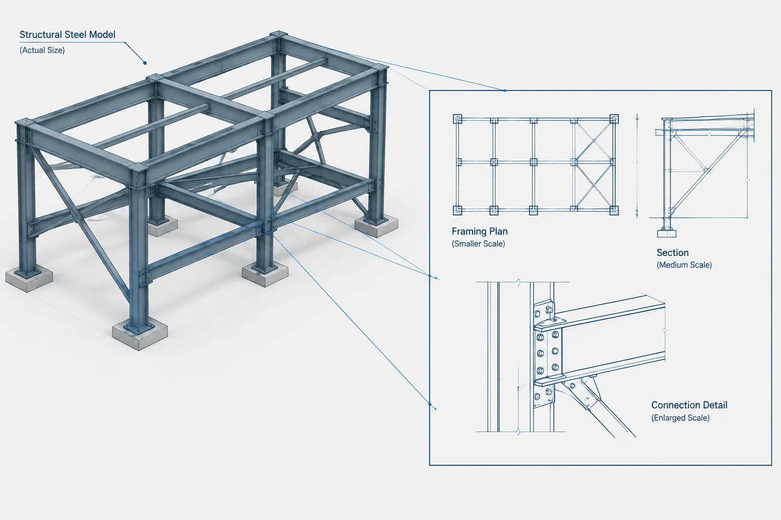
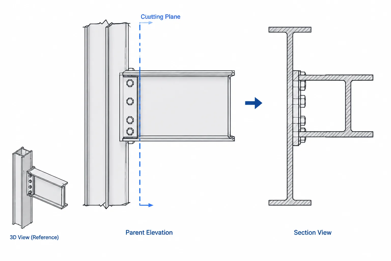
In a CAD model, check the assembly in section rather than relying only on elevation. An elevation may make the beam web and plate appear coplanar even when the plate has been placed on the wrong side or intersects another component.
Vertical Geometry and Beam-Web Fit
The vertical position of a shear tab is commonly coordinated with the beam bolt pattern, plate edges, and available web depth. Important references may include top of steel, beam depth, flange faces, rolled fillet regions, cope limits, and the top and bottom plate edges.
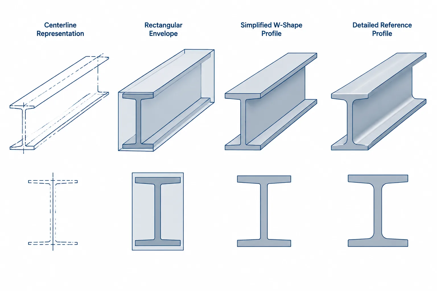
The apparent space between beam flanges is not all equally available for a rectangular plate. Rolled W-shapes have web-to-flange fillets, so a plate extending too close to a flange can conflict with curved material even if a simplified rectangular section shows clearance. Published shape dimensions and relevant detailing dimensions should be checked for the selected beam.
A useful section view should show the real relationship among:
- Beam flange faces and web;
- Rolled fillet or k-region clearance;
- Top and bottom plate edges;
- Hole centers and bolt rows;
- Any top or bottom cope;
- Adjacent welds, stiffeners, or continuity elements.
Supporting-Member Conditions
The supporting member changes how the plate is located and attached. Treating every support as a generic vertical line can hide important geometry.
| Support condition | Key detailing checks |
|---|---|
| Column flange | Flange face location, flange slope or surface geometry where applicable, adjacent flange edges, and access for welding and bolting. |
| Column web | Web face, column flange interference, available access within the column profile, and coordination with stiffeners or other connections. |
| Girder web | Girder flange and fillet clearance, framing elevation, connection congestion on the opposite side, and possible stiffener conflicts. |
| HSS face | Actual HSS outside face, corner-region clearance, wall location, weld access, and any required internal or external reinforcement. |
This table is a coordination guide, not a connection-selection rule. Connection strength, weld design, support reinforcement, and local limit states remain engineering decisions.
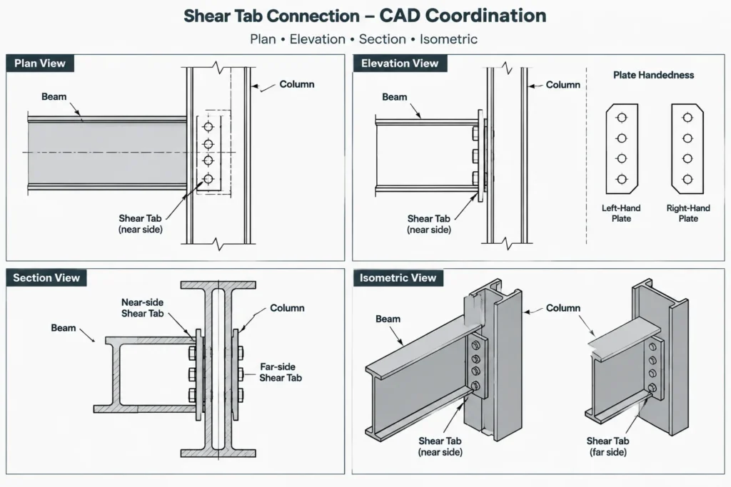
Near-Side and Far-Side Ambiguity
A single plate connects to one side of the beam web, so viewing direction matters. In an elevation, a plate shown against a web may be on the near side or far side. Hidden lines alone may not provide enough clarity, especially in crowded erection drawings.
Use sections, side indicators, or unambiguous notes when the plate side affects fabrication or erection. The model should also preserve this handedness. Mirroring a connection without reviewing plate side, bolt orientation, support geometry, and weld access can create an unintended opposite-hand assembly.
Information the Drawings Should Communicate
The required information depends on drawing type and project practice, but a complete detail generally needs enough information to establish the parts without geometric guesswork.
- Beam and support identification;
- Connection plate mark, thickness, width, and length as specified by the connection design;
- Plate location relative to a defined support datum;
- Beam-end setback or another controlling end reference;
- Hole quantity, type, diameter, and layout from stated datums;
- Bolt specification and installation information required by the project;
- Weld location, extent, and required weld information;
- Plate side relative to the beam web;
- Cope or end-cut geometry where applicable;
- Field-versus-shop connection designation;
- Relevant elevations and member orientation.
Avoid dimensions that can conflict with one another. For example, dimensioning the bolt line independently from the support face, beam end, and both plate edges can overconstrain the same geometry. Identify the controlling dimensions and use reference dimensions only when they improve checking without creating competing instructions.
A Practical CAD Workflow
- Place the supporting member accurately. Confirm its section, rotation, centerline, and physical faces.
- Establish the beam work line. Use the framing layout to locate the supported member before applying end conditions.
- Create the beam end plane. Apply the specified setback, skew, slope, or cut geometry.
- Place the plate from a physical support face. Do not locate it only by eye or by a block insertion point with an undocumented offset.
- Set the plate side. Confirm contact with the intended beam-web face.
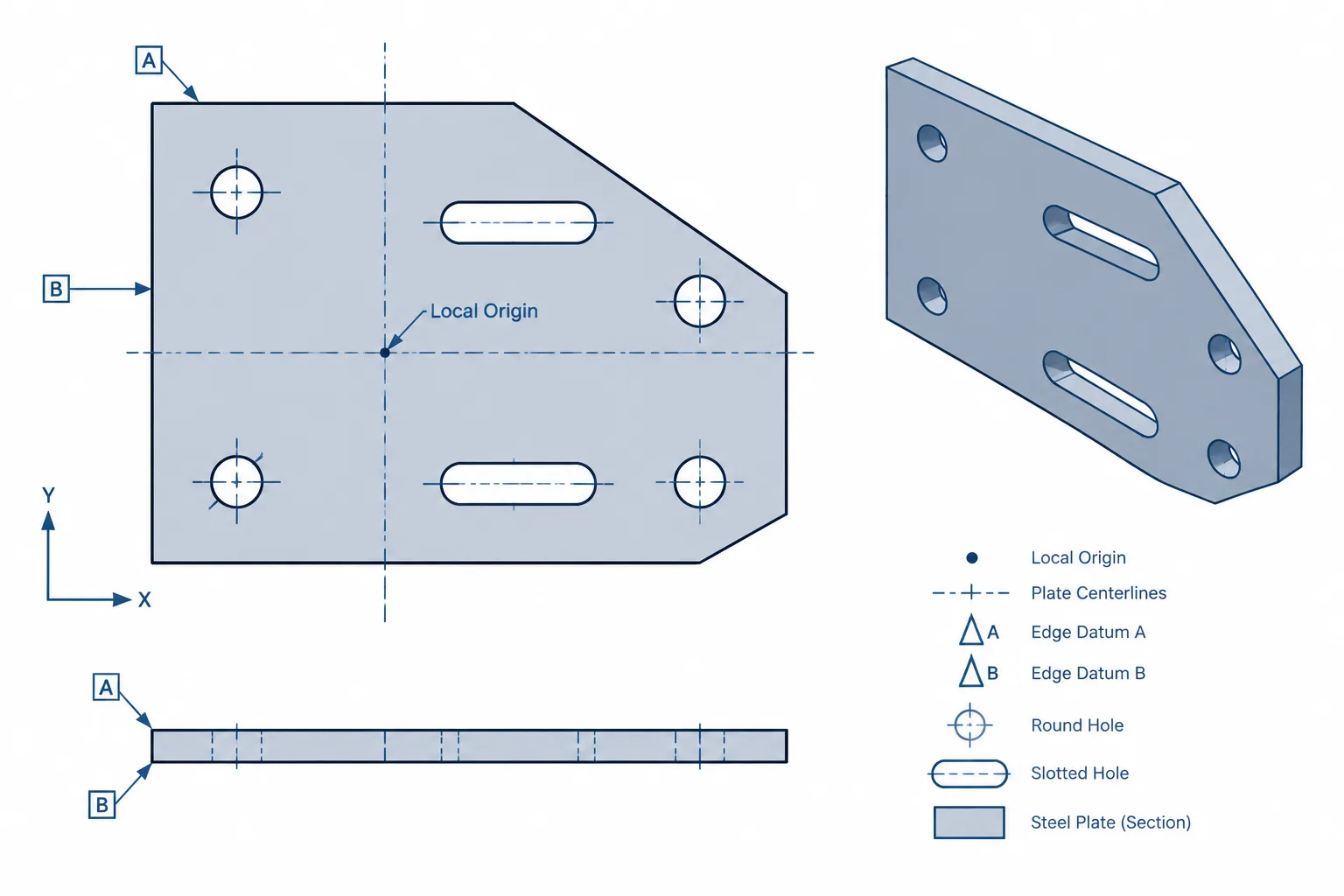
- Lay out holes by center coordinates. Use a consistent datum system and preserve design intent when editing the connection.
- Add the real beam profile needed for clearance checks. Include flange thickness and rolled fillet regions where they affect fit.
- Review in multiple views. Check elevation, plan, section, and an isometric view for side, offset, and access errors.
- Generate drawings from verified geometry. Confirm that hidden-line settings and view direction do not obscure the plate location.
Final Detailing Checklist
- Is the support face clearly distinguished from the support centerline?
- Is the beam setback measured from the intended datum?
- Does the plate contact the correct face of the beam web?
- Are hole centers coordinated between the plate and beam?
- Does the plate clear beam flanges, fillets, and any cope boundaries?
- Are the plate and bolts accessible for the intended erection sequence?
- Have opposite-side connections, stiffeners, welds, and other framing been checked?
- Is the connection handedness clear in both the model and drawings?
- Are shop and field operations identified consistently?
- Has the final geometry been checked against the connection design rather than a generic CAD block?
Good shear tab connection detailing is primarily an exercise in datum control and physical coordination. When the support face, beam end, web face, plate edges, and hole centers are modeled as distinct references, the resulting shop and erection information becomes easier to review and less dependent on assumptions.