This page provides a concise dimensional and CAD reference for the RHS 150x120x6 cold-formed welded rectangular steel tube. It is intended for users checking the section designation, principal dimensions, corner geometry, sectional area, unit weight, and associated DWG resource.
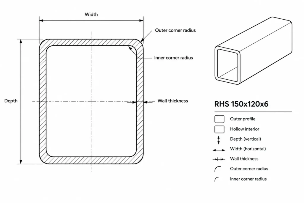
The verified source information below identifies a depth of 150 mm, width of 120 mm, and thickness of 6 mm. Keep the depth and width orientation clear when placing or rotating the section in a drawing, model, section schedule, or connection detail.
RHS 150x120x6
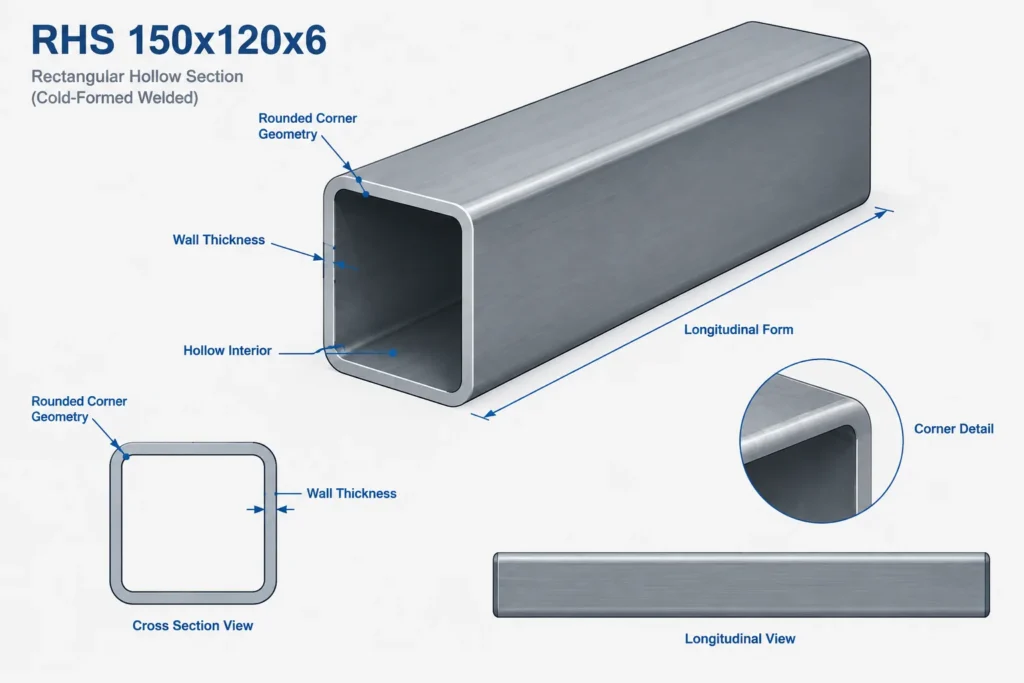
Cold Formed Welded Rectangular Steel Tubes
refer to : EN 10219-2
the European standard that specifies tolerances, dimensions, and sectional properties for cold-formed welded structural hollow sections made of non-alloy and fine grain steels. It complements EN 10219-1, which covers technical delivery conditions.
Dimension : 150x120x6
Depth : 150 mm
Width : 120 mm
Thickness : 6 mm
Outer Corner Radius : 12 mm
Inner Corner Radius : 6 mm
Sectional Area : 30.03 cm2
Unit Weight : 23.6 kg/m
How to Read the RHS 150x120x6 Designation
In this designation, the listed dimensions correspond to the section depth, width, and wall thickness. For this profile, those values are 150 mm, 120 mm, and 6 mm respectively. Because the depth and width are different, drawing orientation matters even though the same section can be rotated in a model or detail.
Verified Section Reference
- Section type: Cold-formed welded rectangular steel tube
- Reference: EN 10219-2
- Dimension: 150x120x6
- Depth: 150 mm
- Width: 120 mm
- Thickness: 6 mm
- Outer corner radius: 12 mm
- Inner corner radius: 6 mm
- Sectional area: 30.03 cm²
- Unit weight: 23.6 kg/m
Corner Geometry in Drawings and Models
An RHS should not automatically be drafted as a sharp-cornered rectangle. The outer and inner corner radii describe the curved corner regions produced by the forming process. Representing these radii is useful in enlarged section views, close-fit connection details, fabrication models, and clearance checks.
For simplified general-arrangement drawings, users may choose a less detailed graphic representation. The section designation and orientation should still remain unambiguous, and fabrication-sensitive details should be checked against the referenced geometry.
Using Sectional Area and Unit Weight
Sectional area describes the amount of material in the cross-section and is used in several engineering calculations. Unit weight expresses the section mass per unit length and can support material takeoffs when combined with member length. These values should be used with consistent units and an appropriate design method.
Neither sectional area nor unit weight is a load-capacity value. Capacity also depends on material properties, member length, restraint, loading, connection behavior, and applicable design requirements. Those project-specific checks are outside the scope of a dimensional reference page.
DWG and Detailing Workflow
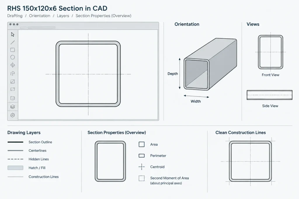
The supplied DWG can be used as a starting reference for CAD coordination. After insertion, confirm drawing units, scale, layer organization, section orientation, and corner representation before incorporating the geometry into a project file. Do not infer connection dimensions, weld requirements, bolt layouts, or design capacity from the section outline alone.
Related Reference Topics
Users working with this profile may also need guidance on rectangular hollow sections, EN 10219-2 dimensional conventions, hollow-section corner radii, unit-weight calculations, sectional-area concepts, welded HSS connections, base plates, and CAD layer management. These related topics help connect the section data to practical drafting and engineering workflows without replacing project-specific verification.
Frequently Asked Questions
What does RHS 150x120x6 mean?
RHS identifies a rectangular hollow section. On this page, 150 mm is the depth, 120 mm is the width, and 6 mm is the thickness.
Which standard is referenced for this section?
The source content refers to EN 10219-2 for dimensions, tolerances, and sectional properties associated with cold-formed welded structural hollow sections.
Why are the inner and outer corner radii important?
Corner radii affect the actual profile geometry near each corner. They can matter when preparing accurate CAD outlines, checking nearby plates or fittings, and producing enlarged fabrication details.
Is 23.6 kg/m the total weight of a member?
No. It is the listed unit weight per meter. A member takeoff requires the relevant member length and consistent units.
Does the DWG establish the section’s structural capacity?
No. A CAD outline is a geometry resource, not a capacity calculation. Structural verification must consider material, loading, restraint, member behavior, connections, and the applicable design requirements.
Should the section be drawn with sharp corners?
Not when detailed corner geometry is important. The verified data lists an outer corner radius of 12 mm and an inner corner radius of 6 mm. Simplified drawings should still identify the section clearly.