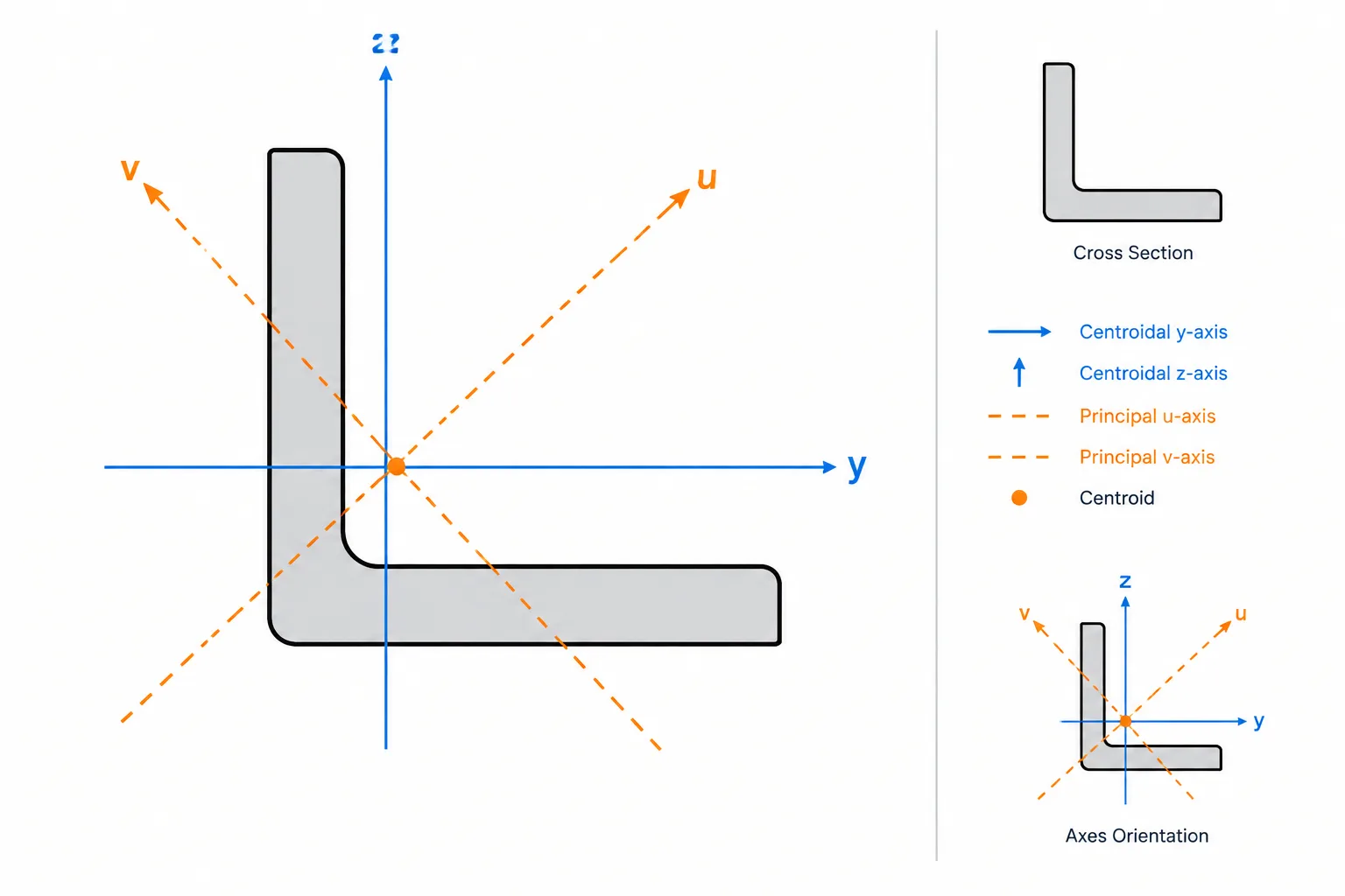
Most steel shape tables emphasize the familiar area moments of inertia, Ix and Iy. These properties describe how area is distributed about two selected axes. For symmetric W-shapes, HSS, channels, and tees in their conventional orientations, those values often support straightforward strong-axis or weak-axis calculations.
Unsymmetric sections require another property: the product of inertia, commonly written Ixy. It identifies coupling between the selected x and y axes. This becomes important when working with single angles, unsymmetric built-up sections, offset plates, or CAD geometry whose axes do not coincide with the section’s principal axes.
What is the product of inertia?
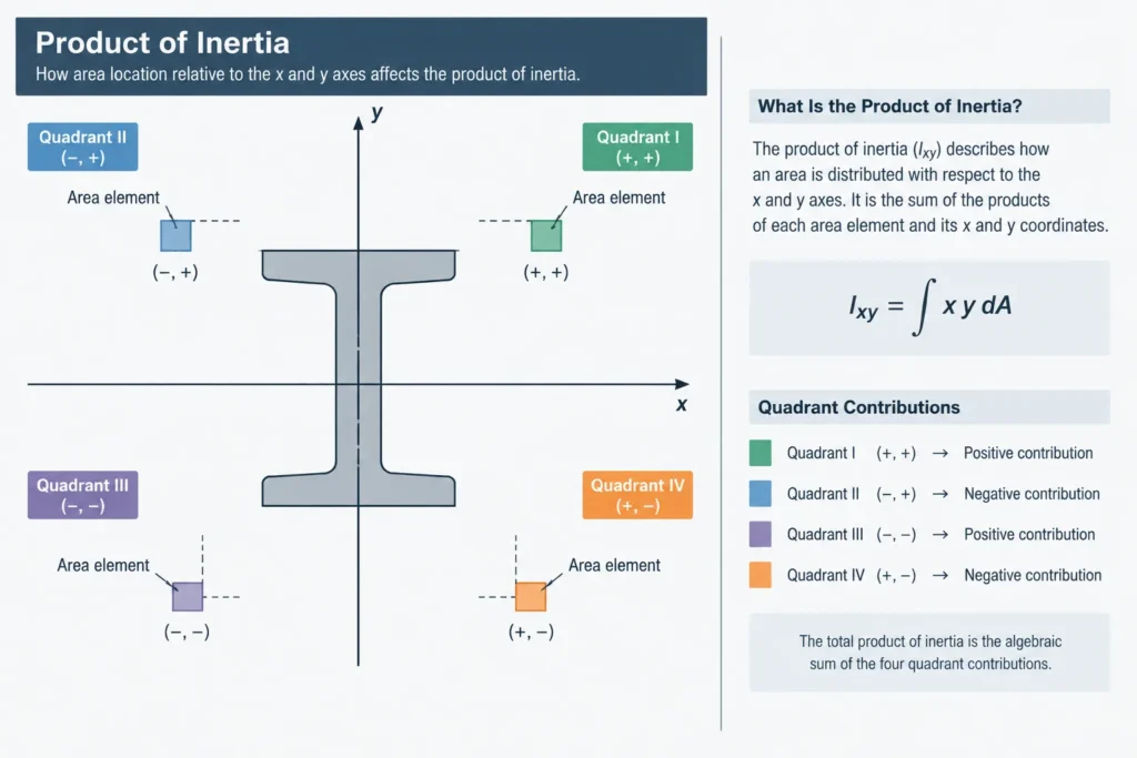
The product of inertia of an area is defined conceptually by:
Ixy = ∫ x y dA
Each small area contributes according to its signed x and y distances from the selected axes. Area in different quadrants can make positive or negative contributions, depending on the coordinate convention. As a result, Ixy may be positive, negative, or zero.
The units are length to the fourth power, matching the units used for Ix and Iy. Product of inertia is not a mass property unless the calculation specifically concerns mass distribution. In steel section tables and section-property software, it normally refers to cross-sectional area.
Why symmetry often makes Ixy zero
When a centroidal axis is also an axis of symmetry, contributions on opposite sides of that axis cancel. For a section with at least one properly aligned symmetry axis, the centroidal x-y axes can usually be selected so that Ixy equals zero.
| Section or arrangement | Typical centroidal-axis behavior | Practical note |
|---|---|---|
| W-shape or similar doubly symmetric I-section | Ixy is zero on the geometric symmetry axes | The familiar strong and weak axes are principal axes. |
| Rectangular or round HSS | Ixy is zero on aligned centroidal symmetry axes | Rotating the CAD object without rotating the reported axes can produce a nonzero global-axis value. |
| Channel | Ixy is zero when one centroidal axis follows its symmetry axis | This does not mean the shear center is located at the centroid. |
| Structural tee | Ixy is zero on centroidal axes aligned with its symmetry axis | The section remains unsymmetric about the perpendicular axis, but the aligned axes are principal axes. |
| Single angle | Ixy is generally nonzero for centroidal axes parallel to the legs | Its principal axes are rotated relative to the legs. |
| Unsymmetric built-up section | Usually nonzero on convenient horizontal and vertical axes | Principal-axis properties should be calculated or obtained from verified software. |
A zero product of inertia therefore does not prove that a section is doubly symmetric. A tee demonstrates the distinction: it has one symmetry axis, and that is enough for properly aligned centroidal axes to be principal axes.
Principal axes and Ixy
Principal axes are centroidal axes oriented so that the product of inertia is zero. The corresponding moments of inertia are the principal moments of inertia. One is the maximum centroidal moment of inertia, and the other is the minimum.
For a single angle, axes parallel to the legs are convenient for drawing and fabrication, but they are generally not principal axes. The principal axes are rotated through the centroid. Shape references may identify these with labels such as major and minor principal axes or with another axis notation. Always check the definitions used by the particular table or software output rather than assuming that every x and y label means the same thing.
This distinction also explains why the visual orientation of a section is not enough to identify its bending behavior. A leg-horizontal, leg-vertical angle can still bend about rotated principal directions.
How Ixy affects bending interpretation
The familiar flexure expression based on a single moment of inertia assumes bending about a principal centroidal axis or another axis for which coupling is absent. If moments are resolved about nonprincipal x and y axes and Ixy is not zero, bending about one selected axis contributes to stress variation in both coordinate directions.
This behavior is commonly called unsymmetric bending. It can occur when:
- a single angle carries load that does not align with a principal axis;
- a built-up section has plates or shapes arranged asymmetrically;
- a member is rotated relative to the analysis coordinate system;
- an attachment shifts the composite centroid and changes the section axes;
- loads are entered in global directions while properties are defined in local section directions.
The neutral axis under a particular loading condition may therefore be rotated relative to both the drawn legs and the selected x-y axes. It should not automatically be placed perpendicular to the moment vector using a symmetric-section assumption.
Calculating Ixy for a built-up steel section
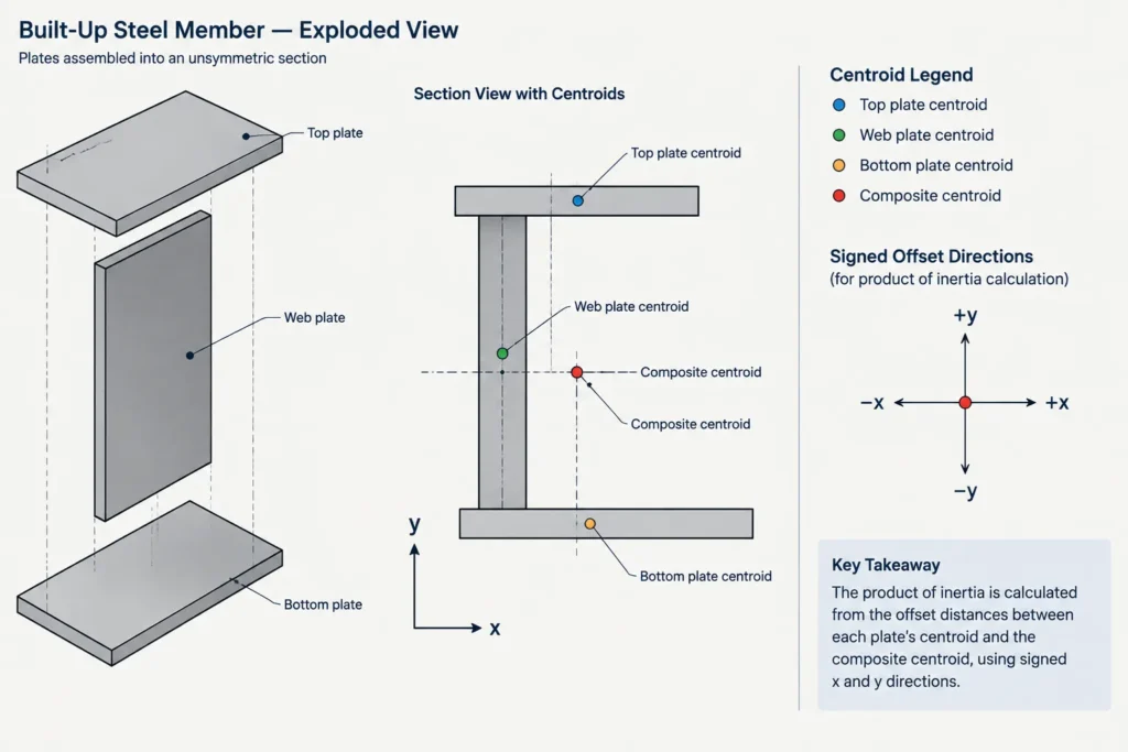
A component-based calculation can be used for plates and simple shapes. First establish the composite centroid, because principal-axis work should normally begin with centroidal properties. For each component, combine its product of inertia about its own centroidal axes with the offset term:
Ixy = Σ[Ixy,component + A Δx Δy]
Here, Δx and Δy are signed distances from the composite centroid to the component centroid. A rectangle aligned with its own centroidal horizontal and vertical axes has a local product of inertia of zero, but its offset term may not be zero. The signs of both offsets must be preserved.
Recommended manual workflow
- Sketch the complete cross section and establish a consistent positive x and y direction.
- Divide the section into nonoverlapping components.
- Determine each component area and centroid location.
- Calculate the composite centroid before shifting properties.
- Obtain each component’s local Ix, Iy, and Ixy for axes parallel to the selected composite axes.
- Apply the appropriate parallel-axis terms, retaining signed x and y offsets for Ixy.
- Sum the component properties and then determine the principal-axis orientation and principal moments if required.
Subtracted openings require consistent negative-area treatment. Overlapping plates or duplicated CAD regions will corrupt the area, centroid, and every derived property.
Checking Ixy in CAD and section-property software
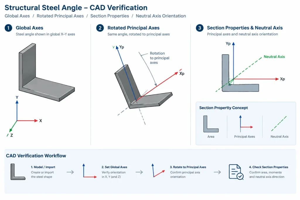
CAD output is useful, but the reported value only has meaning when its reference system is understood. Before comparing software results with a steel shape table, verify:
- Origin: Is the property reported about the centroid, the drawing origin, or a user-selected point?
- Axis direction: Are x and y global drawing axes, object axes, or principal axes?
- Geometry: Does the region include fillets, rounded HSS corners, holes, weld material, or simplified square corners?
- Units: Are the source geometry and property output using the intended unit system?
- Sign convention: Does the software define positive rotation and Ixy in the same way as the comparison calculation?
- Region integrity: Is the profile closed, free of overlaps, and composed of the intended areas only?
A useful CAD check is to rotate the geometry while keeping the global axes fixed. The global-axis values of Ix, Iy, and Ixy should change, while the principal moments remain unchanged. If the software automatically reports principal properties, its displayed Ixy may be zero even though the section has a nonzero product of inertia about the drawing axes.
Do not confuse Ixy with J, Q, or Cw
- Ixy: Product of inertia associated with two selected in-plane axes.
- J: A torsional property whose interpretation depends on the section and calculation context.
- Q: First moment of area, commonly used in shear-stress and shear-flow calculations.
- Cw: Warping constant used in torsional and stability analysis of applicable open sections.
These properties can share similar units in some reporting formats, but they are not interchangeable and describe different section behavior.
Practical drawing and review guidance
For an angle or unsymmetric built-up member, show enough orientation information for another user to reconstruct the section consistently. Identify member local axes where analysis results depend on them, and do not rely only on generic labels such as major axis or x-axis without defining their direction.
When transferring properties between a shape table, calculation sheet, CAD region, and analysis model, record whether the values are centroidal, principal, leg-parallel, or global. Many apparent property conflicts are actually reference-axis conflicts.
The key review question is simple: about which axes was this product of inertia calculated? Once the origin, orientation, and sign convention are known, Ixy becomes a practical tool for understanding single angles, rotated sections, and unsymmetric steel assemblies rather than an obscure table entry.