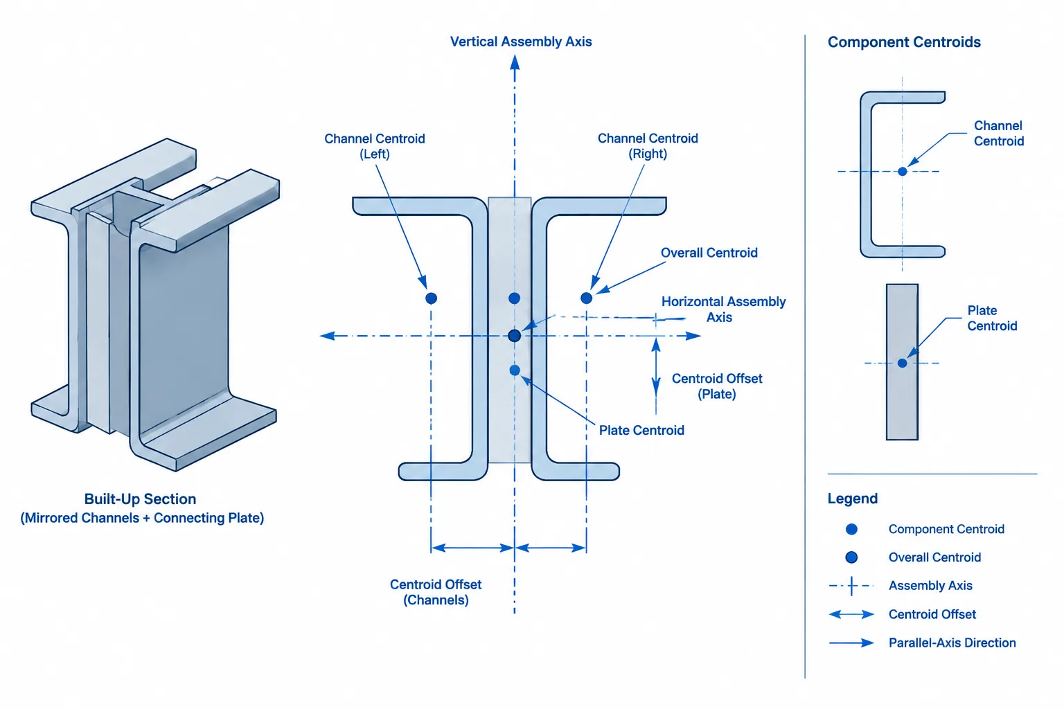
Published steel shape tables provide section properties for individual W-shapes, channels, angles, tees, HSS, and other standard sections. A built-up member, however, may combine two or more shapes with plates, gaps, or mirrored orientations. Its overall centroid and moment of inertia usually cannot be found by simply adding the tabulated values.
The parallel-axis theorem provides a practical way to move each component’s centroidal moment of inertia to a common axis for the complete assembly. It is useful for preliminary calculations, independent checks, CAD verification, and comparison of built-up arrangements. The method is geometric, but the resulting properties represent the real member only when the components are connected so that they act together as assumed.
Why component properties cannot always be added directly
Areas can be added directly because area does not depend on the location of an axis. Centroidal moments of inertia are different: each tabulated value is normally measured about an axis passing through that individual shape’s centroid.
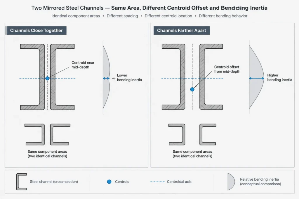
Consider two channels placed back-to-back with a space between them. Each channel has its own centroidal axes, while the channel pair has a separate centroid and a different set of assembly axes. If the channels move farther apart, the total steel area remains unchanged, but the moment of inertia about the axis between them can increase substantially. The parallel-axis term captures this effect.
For one component shifted to an axis parallel to its centroidal axis, the relationship is:
I = Ic + Ad2
- I is the component’s moment of inertia about the selected assembly axis.
- Ic is its moment of inertia about a parallel axis through its own centroid.
- A is the component area.
- d is the perpendicular distance between the component centroid and the assembly axis.
For an assembly, apply the relationship to every component and sum the results.
Start by defining the built-up section clearly
A reliable calculation begins with an unambiguous cross-section sketch. Show every shape and plate in its actual orientation, including spacing and offsets. Assign a consistent horizontal axis and vertical axis, then choose a convenient datum from which all centroid coordinates will be measured.
The datum does not need to pass through the steel. It only needs to remain consistent. A face of a plate, a centerline between mirrored shapes, or a clearly defined CAD origin can all work.
For every component, record:
- Shape or plate identification
- Cross-sectional area
- Centroid coordinates relative to the selected datum
- Centroidal moments of inertia about axes parallel to the assembly axes
- Rotation or reflection of the component section
Use verified section properties from the applicable shape reference. Do not estimate rolled-shape properties from simplified rectangles when accurate published values are available. Rolled fillets, tapered elements, and other profile details can make simplified CAD geometry disagree with tabulated properties.
Step-by-step calculation workflow
1. Find the total area
For an assembly made entirely of steel, the gross geometric area is the sum of the component areas:
Atotal = ΣAi
Open gaps are not components and contribute no area. Holes, slots, copes, and other removals require separate treatment if the calculation is intended to represent a net or locally reduced section.
2. Locate the assembly centroid
Calculate the area-weighted centroid coordinates:
x̄ = Σ(Aixi) / ΣAi
ȳ = Σ(Aiyi) / ΣAi
Symmetry can simplify this step. For example, the centroid of a correctly mirrored pair lies on its axis of symmetry. Symmetry should still be confirmed from the actual component geometry and spacing rather than assumed from the member description.
3. Determine each centroid offset
For every component, calculate its horizontal and vertical distance from the assembly centroid:
Δxi = xi − x̄
Δyi = yi − ȳ
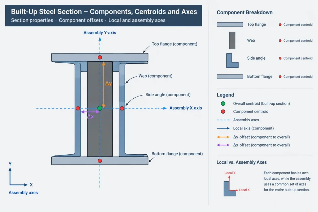
The sign matters while locating the centroid, but the offset becomes squared in the parallel-axis term.
4. Transfer and sum the moments of inertia
For horizontal and vertical assembly axes:
Ix = Σ(Ix,i + AiΔyi2)
Iy = Σ(Iy,i + AiΔxi2)
Notice that the perpendicular distance is used. A horizontal centroid shift affects the moment of inertia about the vertical axis, while a vertical shift affects the moment of inertia about the horizontal axis.
5. Calculate section modulus where appropriate
Once the assembly centroid and moment of inertia are known, the elastic section modulus to a selected extreme fiber is:
S = I / c
An unsymmetrical section may have different distances to its opposite extreme fibers. In that case, report the section modulus separately for each side rather than treating it as one universal value.
Property-by-property treatment
| Property | Typical assembly treatment | Important caution |
|---|---|---|
| Area, A | Add component areas | Account for actual removals when net properties are required |
| Centroid | Use area-weighted coordinates | Use one datum and consistent units |
| Moment of inertia, I | Add centroidal values and parallel-axis terms | Component axes must be parallel to the assembly axes |
| Elastic section modulus, S | Divide assembly I by the applicable extreme-fiber distance | Opposite sides may have different values |
| Radius of gyration, r | Calculate from the completed assembly using √(I/A) | Do not average component radii of gyration |
| Plastic section modulus, Z | Locate the plastic neutral axis and sum first moments of area | It is not obtained by applying I/c |
| Torsional properties | Require methods appropriate to the complete section | J and Cw generally should not be combined by the bending parallel-axis procedure |
Rotated angles, channels, and other unsymmetrical shapes
The basic workflow is easiest when each component’s centroidal axes are parallel to the selected assembly axes. Rotation complicates the calculation because moments and products of inertia may need to be transformed before the parallel-axis terms are applied.
This is particularly important for angles and other unsymmetrical shapes. Their principal axes are generally rotated relative to axes aligned with the legs. A table may report properties about several axis systems, so the property headings and axis diagrams must be checked before values are entered.
Mirroring a shape can also change the sign of its product of inertia even though its area and centroidal moments of inertia remain unchanged. In a symmetric built-up pair, opposing product-of-inertia terms may cancel, but that should be demonstrated from the geometry rather than assumed.
Using CAD without letting the drawing control the answer
CAD region and mass-property tools can provide a useful independent check. Create closed profiles for all steel components, place them at the actual cross-sectional coordinates, and combine them only if the software workflow preserves the intended geometry. Confirm the unit system before reading area, centroid, or inertia results.
CAD results may differ from published shape properties when the model uses idealized sharp corners, approximate fillet radii, traced outlines, or nominal rather than actual geometry. For rolled shapes, verified tabulated properties are normally the better component input. CAD is especially valuable for confirming component placement, plate geometry, centroid location, and extreme-fiber distances.
A good checking procedure is to compare:
- The summed component area with the CAD region area
- The calculated centroid with the CAD centroid marker
- The expected symmetry with the reported centroid coordinates
- The assembly inertia with an independent spreadsheet or calculation
- The extreme-fiber distances with the actual section outline
Geometric properties do not guarantee composite action
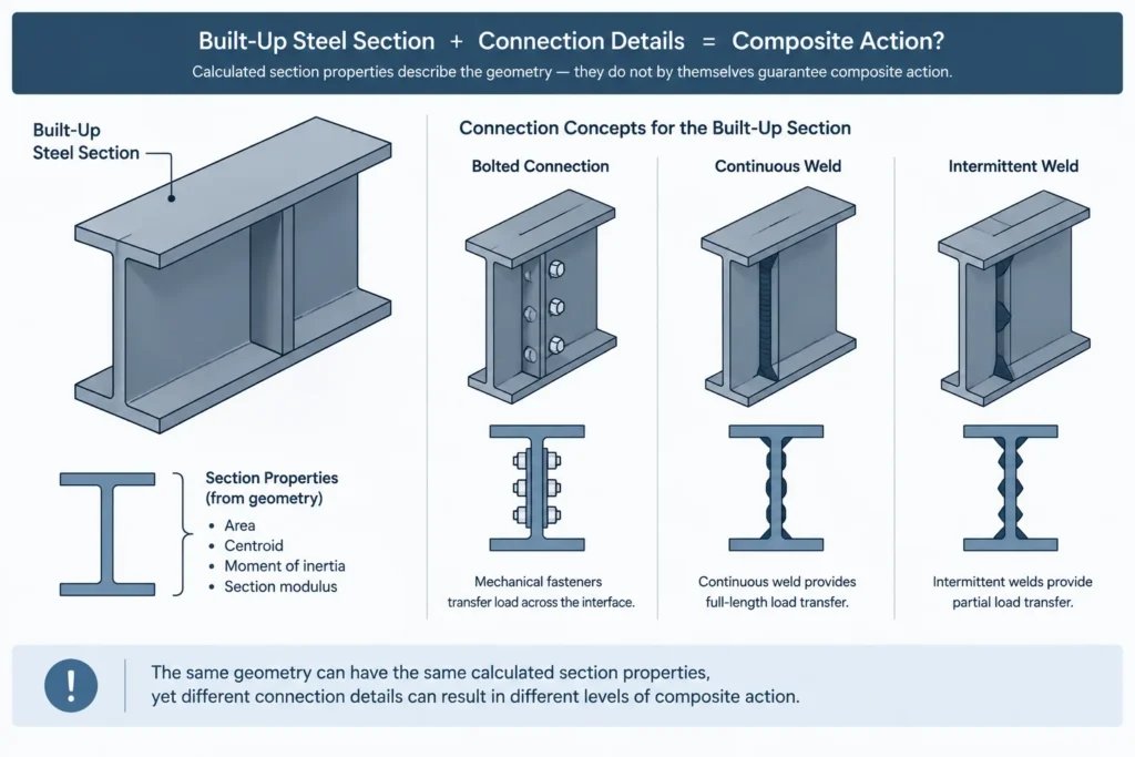
The parallel-axis theorem describes the geometry of an assumed unified cross-section. It does not determine whether separate shapes actually develop full built-up action. Welds, bolts, stitch spacing, connectors, intermediate plates, and load transfer between components all influence structural behavior.
A pair of shapes touching each other is not automatically equivalent to a fully connected built-up member. Likewise, widely spaced components may have an attractive calculated moment of inertia while requiring substantial connection forces to act together. Connection design, local effects, stability, slenderness, and applicable design provisions require separate engineering evaluation.
Common calculation mistakes
- Adding tabulated centroidal inertias without including component offsets
- Using the wrong perpendicular distance in the parallel-axis term
- Mixing properties reported about different axis systems
- Forgetting to rotate or reflect unsymmetrical component properties
- Averaging section modulus or radius of gyration values
- Using nominal shape outlines as if they were exact rolled profiles
- Applying the bending method directly to torsional properties
- Calculating one section modulus for an assembly with unequal extreme-fiber distances
- Assuming geometric assembly properties prove adequate interconnection
A practical worksheet structure
A transparent worksheet should include separate columns for component area, centroid coordinates, centroidal inertias, centroid offsets, squared offsets, and parallel-axis contributions. Keep source properties visually distinct from calculated values. A small section sketch with axis arrows and a marked datum prevents many sign and orientation errors.
Before using the result, verify the shape data, units, orientation, component spacing, connection assumption, and purpose of the calculation. The parallel-axis theorem is straightforward, but its accuracy depends on defining the built-up section correctly and understanding which properties can—and cannot—be assembled by simple summation.