A structural steel elevation compresses three-dimensional geometry into a flat view. That works well until connection material appears on both sides of a beam web, column flange, gusset plate, or HSS wall. Two plates may overlap in projection even though they occupy different planes. Bolt heads and nuts may also look interchangeable unless the view direction and drawing convention are clear.
Understanding near-side vs. far-side steel detailing helps prevent mirrored connections, reversed bolt orientations, misplaced holes, and incorrect shop assemblies. The essential question is simple: Which face of the member is closest to the viewer? The answer must remain consistent as the detail moves between plans, elevations, sections, shop drawings, and the CAD model.
What Near Side and Far Side Mean
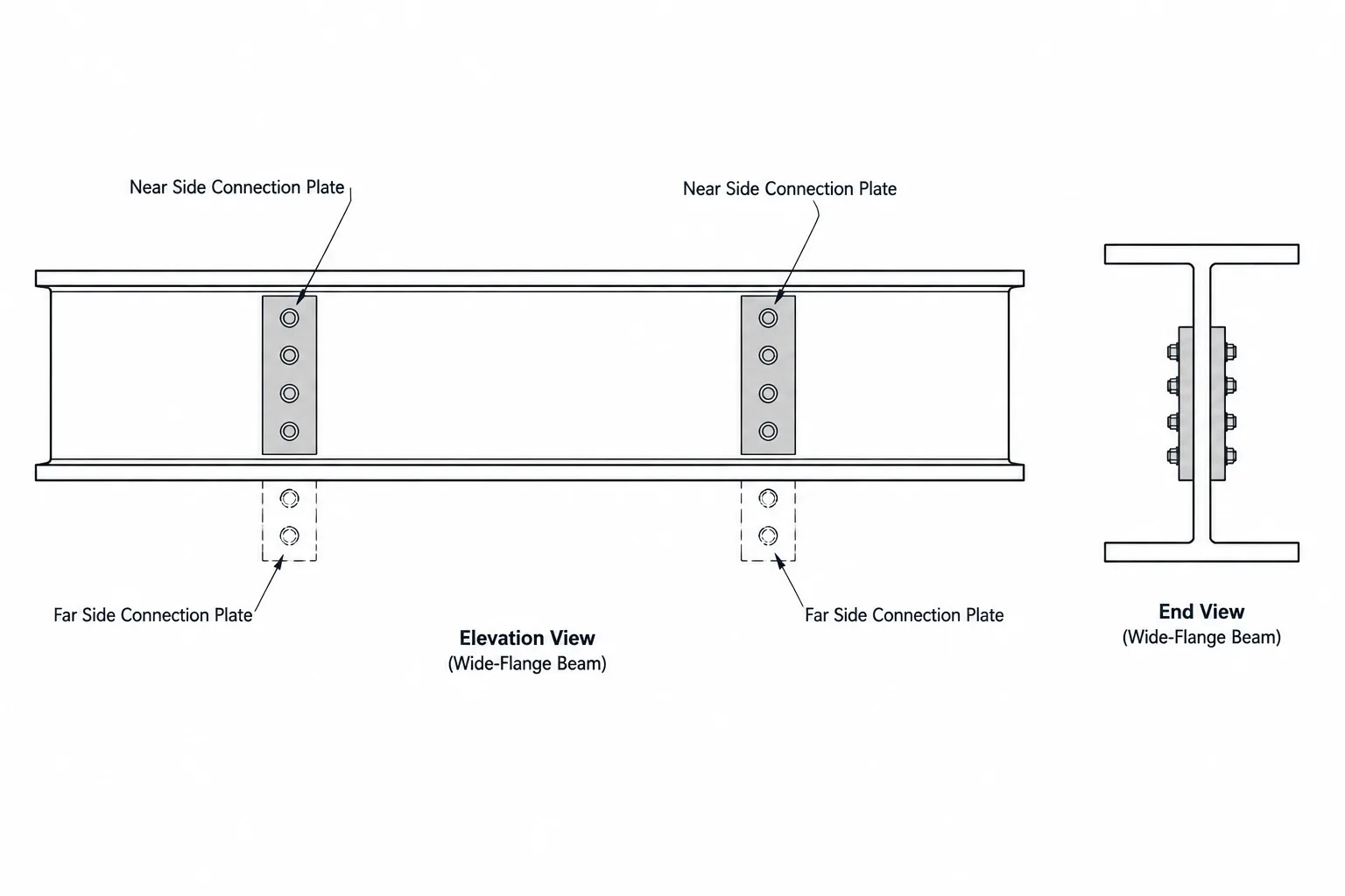
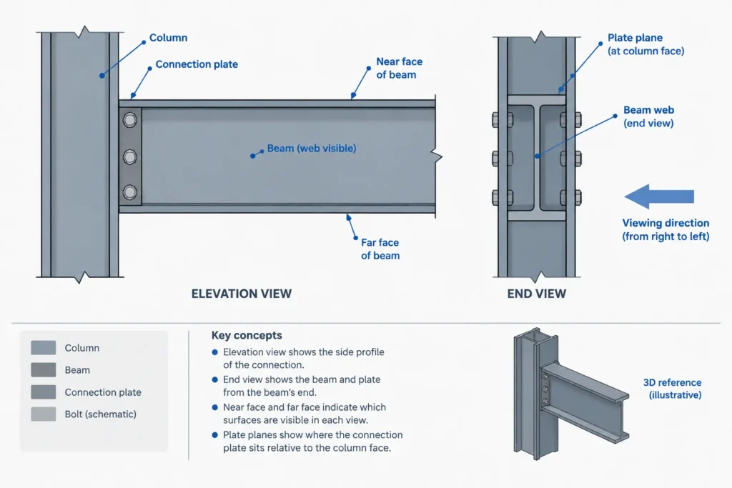
The near side is the face, plate, or connection component closest to the observer in the stated view. The far side is behind the member or behind another component from that same viewing direction. These terms are view-dependent rather than permanent properties of a piece.
A plate attached to the near side of a beam web in one elevation may appear on the far side when the viewing direction is reversed. Likewise, the east face of a column is not automatically the near face; it is near only when the view is looking from east toward west.
Reliable interpretation therefore depends on three items:
- The direction from which the view is taken
- The member orientation and local faces
- The graphic convention used to distinguish visible and concealed material
Why the Distinction Matters
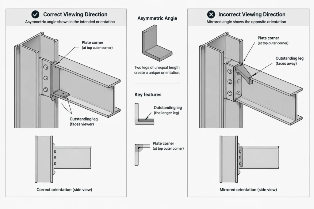
Many steel connections are not symmetric through the member centerline. A shear plate may occur on only one side of a web. A brace gusset may be offset to align with a brace work line. An angle may have its outstanding leg turned in a specific direction. A stiffener may be required opposite another connection component but not on the viewer-facing side.
If a detail is accidentally mirrored, its basic outline can still look plausible. The error may not become obvious until bolt holes fail to align, a plate conflicts with another member, or the assembly is placed in the field. Near-side and far-side information is therefore part of the connection geometry, not merely a drafting preference.
Common Drawing Methods
There is no single graphic device that solves every situation. Drawing sets commonly combine visible outlines, hidden lines, section views, directional notes, and piece labels. Project-specific drafting conventions should govern when they are defined.
| Method | Useful for | Potential limitation |
|---|---|---|
| Visible and hidden linework | Showing components on opposite sides in one view | Can become crowded where plates, welds, and bolts overlap |
| Near-side or far-side note | Identifying the physical side of a component directly | Requires an unambiguous view direction |
| Section or end view | Showing offsets, plate planes, and member faces | Must be coordinated with the parent view |
| Separate opposite-side detail | Documenting substantially different connection faces | Creates another view that must remain synchronized |
| Piece marks and callouts | Tracking individual plates and angles | A mark identifies a piece but may not fully define its orientation |
Hidden linework should not be treated as the only source of side information when the view is dense. A small end view or section can often communicate the assembly more clearly than numerous overlapping dashed lines.
Establish the Viewing Direction First
Before interpreting a connection elevation, identify how the observer is looking at the member. Useful indicators may include section arrows, elevation titles, grid references, orientation marks, or adjacent framing. Do not infer the viewing direction solely from where a plate happens to be drawn.
For a beam elevation, confirm whether the view shows the member from one side or the other. For a column elevation, determine which building direction lies toward the viewer. For a brace connection, trace the brace work line and determine whether the gusset is centered, near-side mounted, or far-side mounted.
Once the view direction is established, mentally assign local faces. Neutral labels such as Side A and Side B can be useful during modeling, especially when compass directions do not align neatly with sloped or skewed members.
Reading Plates and Angles in Projection
Plates on member webs
A plate parallel to a beam web may project directly over the web in elevation. Its side cannot always be determined from the outline alone. Look for a section, weld indication, hidden-line treatment, or explicit side note. If none is present and side placement affects fabrication, the drawing needs clarification.
Connection angles
An angle can be especially easy to reverse because its legs may collapse into a simple profile in elevation. Confirm which leg contacts the supporting member, which leg connects to the supported member, and which direction the outstanding leg faces. An end view is often the clearest way to show this relationship.
Paired components
When plates, angles, or stiffeners occur on both sides, do not automatically assume the pieces are identical. Their hole patterns, lengths, weld access, or edge conditions may differ. Wording such as “each side” communicates quantity and placement, but it should be used only when the geometry truly applies to both sides.
Bolts, Holes, and Viewing Side
A bolt line shown in elevation usually identifies the projected bolt or hole location, but it may not reveal which end contains the head or nut. Bolt orientation can matter where installation access, tightening access, projection, or interference is limited.
A drafter should distinguish between three separate facts:
- Where the bolt axis passes through the connected plies
- Which components are included in the grip
- Which side receives the head, nut, or other specified assembly components
Do not infer bolt orientation from a generic symbol unless the project legend clearly defines that symbol. If orientation matters, communicate it through an appropriate view, note, or assembly representation. Hole geometry should remain aligned to the actual plate coordinate system rather than being redrawn by eye in each elevation.
Mirroring Is Not the Same as Viewing from the Opposite Side
CAD mirror commands can produce geometry that looks like an opposite-side connection, but mirroring may also reverse details that should remain unchanged. Text, piece marks, weld information, slotted-hole direction, angle handedness, and asymmetric plate edges all require review.
Changing the viewing direction of a correctly modeled three-dimensional assembly is fundamentally different from creating a new mirrored assembly. The first changes only the observer’s perspective. The second changes the physical geometry.
When a connection is intended to have left-hand and right-hand versions, treat them as controlled variants. Confirm whether the plate shape, hole coordinates, bevels, weld preparation, and attached parts truly mirror. Do not rely on visual similarity alone.
A Practical CAD and Checking Workflow
- Define member orientation. Establish start and end, top and bottom, and local side faces before adding connection material.
- Model or draw in a stable coordinate system. Locate holes and plates from controlled reference lines rather than from the current screen view.
- Set the view direction. Record which side the elevation observes so later users do not have to guess.
- Add an end view or section. Use it to verify plate planes, angle legs, offsets, and bolt direction.
- Check asymmetric features. Review notches, clipped corners, slots, bevels, weld sides, and unequal edge distances for accidental reversal.
- Compare related sheets. Confirm that the erection view, assembly drawing, part details, and model all describe the same orientation.
- Perform a fabrication-minded review. Imagine the member lying in the shop and identify which physical face receives each marked component.
Useful Notes Without Overloading the Drawing
Side notes should identify a component relative to a clearly defined view or member orientation. A vague note such as “plate opposite side” may become unclear when copied into another detail. More durable communication ties the note to a named face, grid direction, view arrow, or assembly orientation.
A note also should not substitute for missing geometry. If a plate offset or angle orientation is important, show it in a section or end view. Notes are most effective when they reinforce a graphic relationship rather than forcing the fabricator to reconstruct it.
Final Review Questions
- Is the viewing direction explicit or readily traceable?
- Can every one-sided component be assigned to a physical member face?
- Are hidden components distinguishable from visible components?
- Does an end view confirm plate and angle orientation?
- Could any CAD geometry have been mirrored unintentionally?
- Do bolt axes, grip plies, and any required installation orientation agree?
- Are shop, erection, and model views consistent?
Near-side and far-side steel detailing is ultimately an exercise in preserving three-dimensional intent through two-dimensional documents. Clear viewing directions, coordinated sections, controlled CAD geometry, and explicit treatment of asymmetric components make that intent easier to fabricate, inspect, and erect.