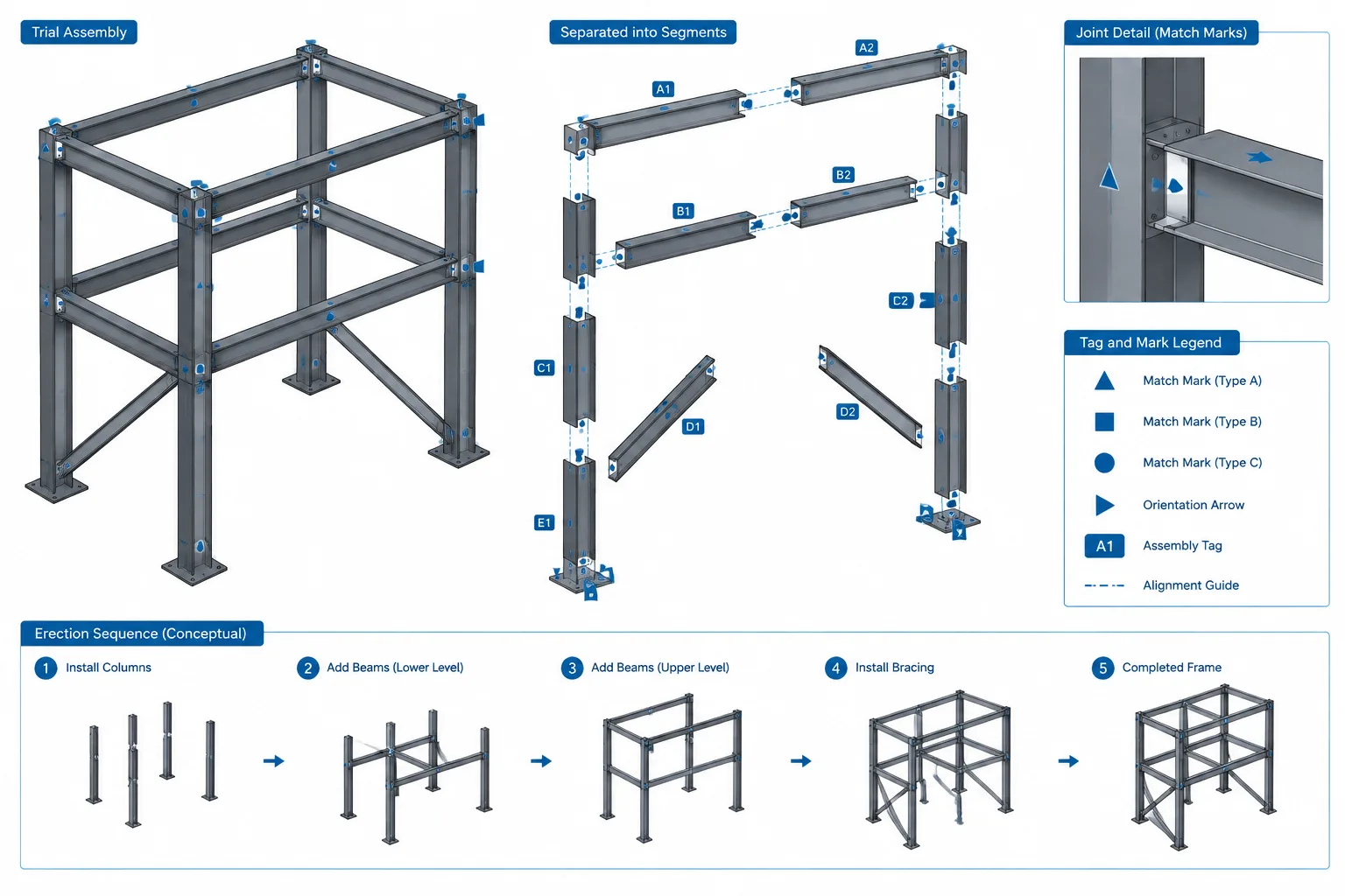
Structural steel match marks identify how specific parts or assemblies relate to one another. Fabricators commonly use them when components must return to a known position after trial assembly, coating, shipping, or separation into manageable pieces. A good match-marking system reduces uncertainty without replacing piece marks, erection marks, dimensions, or approved connection information.
The basic idea is simple: apply coordinated identifiers to mating components so the intended relationship can be recovered later. The practical challenge is making those identifiers clear, durable, unique, and consistent with the shop drawings and erection sequence.
What a Structural Steel Match Mark Communicates
A match mark establishes a relationship rather than merely naming an object. It may indicate that two ends belong together, that a plate has a particular orientation on a member, or that one segment occupies a specific position within a larger assembly.
Typical uses include:
- Identifying mating ends of field-spliced members.
- Preserving the relative position of trial-assembled components.
- Distinguishing similar-looking left-hand and right-hand parts.
- Maintaining the order of segments in long trusses, frames, or built-up assemblies.
- Showing which removable item belongs at a particular location.
- Recovering orientation after an assembly is separated for coating or shipment.
A match mark does not define the complete geometry of a connection. Hole patterns, plate locations, welds, bolt requirements, member setbacks, and other controlling information must still come from the relevant drawings, models, and project documents.
Match Marks vs. Other Steel Identification Marks
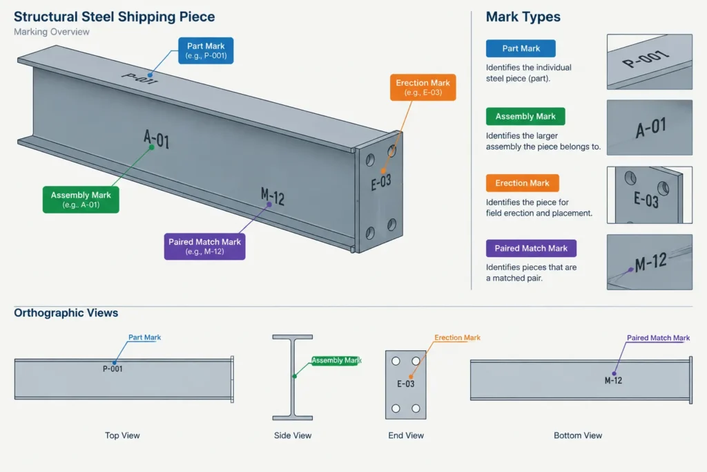
Several identifiers may appear on the same steel component, but they serve different purposes. Treating them as interchangeable can create shop and field confusion.
| Identifier | Primary purpose | Typical relationship |
|---|---|---|
| Part mark | Identifies an individual detail item | One mark may apply to multiple identical parts |
| Assembly or piece mark | Identifies a fabricated shipping member or assembly | Connects the physical assembly to shop and erection documents |
| Erection mark | Supports field location and erection sequencing | Relates a shipped item to its installed position |
| Match mark | Identifies a specific mating relationship or orientation | Links one component, end, or face to another |
| Layout mark | Guides fabrication operations | Indicates cut, bend, hole, weld, or attachment locations |
For example, two splice segments can have different assembly marks while also carrying a shared pair of match marks at their mating ends. The assembly marks identify the segments; the match marks show which ends face each other.
Where Match Marks Are Most Useful
Field splices and segmented members
Long or heavy members may be divided into shipping pieces. Where several splice locations look similar, end-specific match marks help prevent a segment from being reversed or placed in the wrong sequence. This is especially useful when bolt patterns are nearly symmetrical but not truly interchangeable.
Trial-assembled frames and trusses
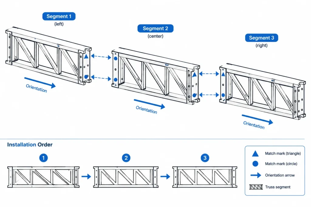
A shop may temporarily assemble complex framing to check fit. Components are then separated for finishing and transportation. Match marks preserve the relationships established during that trial assembly, including sequence, side, and orientation.
Removable connection components
Loose plates, splice material, diaphragms, or other removable items may be fitted to a particular location. Even if nominally similar, fabrication variation or intentional asymmetry can make location control important. A coordinated mark can connect the loose component to its receiving assembly.
Built-up and repeating assemblies
Repeating bays can contain parts that appear identical from a distance. Match marks can differentiate positions when connection geometry, skew, slope, hand, or attachment orientation changes between locations.
Orientation Must Be Part of the System
A match mark is incomplete if it identifies a pair but leaves the mating orientation ambiguous. A plate might fit in more than one rotation, and a member end may appear usable after being turned over. The marking plan should therefore address direction as well as identity.
Orientation can be communicated by combining the identifier with one or more graphical or documented cues:
- Marking adjacent faces near the intended joint.
- Using paired symbols that align when the parts are correctly positioned.
- Adding end, side, top, or sequence notation defined by the project convention.
- Locating marks consistently relative to a member datum.
- Showing the same relationship on an assembly or erection drawing.
Terms such as left, right, near side, and far side should not be used without a defined viewing direction. Member-end references are clearer when they are tied to grid lines, column lines, work points, drawing views, or established local axes.
Developing a Clear Match-Mark Convention
The exact naming format can vary by fabricator and project. What matters is that the convention is documented and does not conflict with existing part or assembly identifiers.
A practical system should be:
- Unique: one mark should not describe unrelated mating conditions.
- Readable: characters and symbols should remain distinguishable in the shop and field.
- Traceable: the mark should correspond to drawings, lists, or model information where needed.
- Orientation-aware: the system should make reversal or rotation detectable.
- Durable: the selected marking method should survive the required handling and processing.
- Nonconflicting: match marks should not be mistaken for piece marks, weld symbols, inspection marks, or layout lines.
Marking methods may include paint markers, tags, stamps, controlled scribe marks, or other shop-approved processes. Selection depends on the material, coating sequence, exposure, appearance requirements, and fabrication procedure. Any method that could damage the steel, affect a fatigue-sensitive area, interfere with coating, or create unacceptable surface conditions requires appropriate project review.
Showing Match Marks on Drawings and Models
Match marks should be documented where they provide value rather than added as unexplained shop-floor notation. A drawing can show the mark beside the relevant end, face, or loose component and include a brief legend defining its purpose.
For multi-segment assemblies, an overall diagram is often more useful than repeating isolated labels on separate sheets. The diagram can show:
- The installed sequence of shipping pieces.
- The mating ends at each splice.
- The reference direction used for orientation.
- The relationship between match marks and assembly marks.
- Any loose components shipped separately.
In a CAD or BIM workflow, match marks can be stored as attributes or object data, but they should also appear in a usable deliverable when field personnel need them. Model-only information may not be visible on printed erection drawings, exported files, or fabrication documents.
Mark Placement and Visibility
The physical location of a mark matters. A mark that is readable in the shop may become hidden after plates are installed, members are stacked, or a connection is bolted. Conversely, a highly visible mark may be undesirable on architecturally exposed steel.
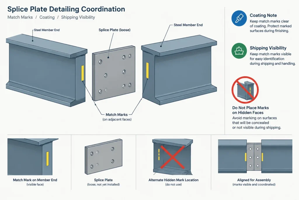
Coordinate placement by asking:
- Will the mark remain visible after fabrication and coating?
- Can it be read while the member is stored in its expected shipping orientation?
- Will another component cover it before field verification?
- Could the mark be confused with a cut line or weld location?
- Is the surface subject to special appearance or treatment requirements?
- Does the mark need to be duplicated on a tag or shipping document?
Placing related marks near the joint can make the relationship intuitive, but access and visibility still need to be checked. For loose pieces, marking both the item and its destination helps prevent separation from destroying the identification chain.
Common Match-Marking Failures
Many problems result from incomplete coordination rather than missing marks. Common failure modes include:
- Using the same identifier at several unrelated joints.
- Marking only one of the two mating components.
- Identifying the pair without showing rotational orientation.
- Allowing coating or surface preparation to remove the mark.
- Placing the identifier where it becomes concealed during assembly.
- Changing a piece mark without updating associated match-mark records.
- Relying on color alone, which may fade or be difficult to distinguish.
- Using handwritten notation that does not match the drawing convention.
Symmetrical appearance is a particular risk. If reversal would change hole alignment, plate orientation, camber direction, connection hand, or installed geometry, the checking process should treat the parts as directional even when their overall outlines look similar.
A Practical Coordination Checklist
- Identify assemblies that will be trial fitted and later separated.
- List field splices, loose parts, and repeated components that could be confused.
- Define a unique match-mark convention and viewing direction.
- Show both identity and orientation at every mating condition.
- Coordinate marks with piece marks, erection drawings, and shipping lists.
- Verify that the marking method is compatible with fabrication and finishing.
- Check visibility in the expected storage, shipping, and erection positions.
- Update the match-mark record when revisions change component relationships.
- Confirm that field personnel receive a drawing or list that explains the system.
Match Marks as Part of Information Control
Match marks are most effective when treated as controlled fabrication information, not as informal notes added after fit-up. They connect physical steel to the intended assembly relationship through disassembly, handling, shipping, and erection.
A reliable system answers three questions: which components belong together, how are they oriented, and where is that relationship documented? When all three answers are clear, match marks can significantly reduce avoidable sorting, rework, and field fit-up uncertainty.


