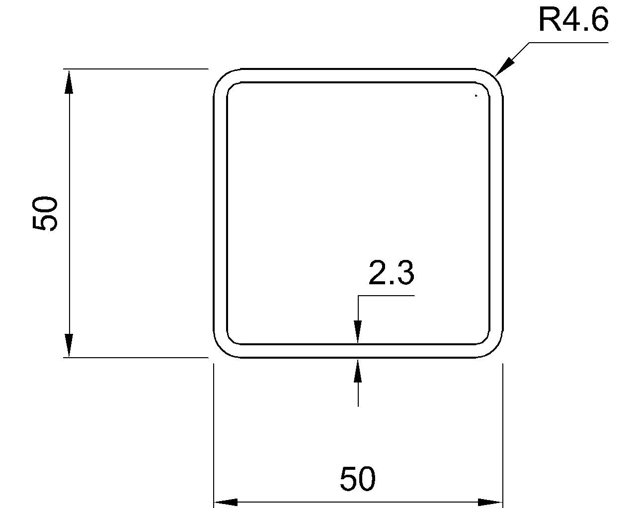
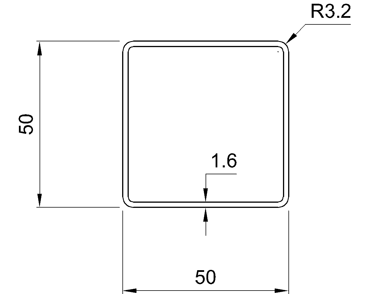
Hybox 355 SHS 30x30x2 is a compact square hollow section (SHS) reference for engineers, detailers, fabricators, and CAD users. This page brings together the listed dimensions, corner radii, sectional area, unit weight, standard reference, and downloadable DWG file.
Use the source data below when checking a drawing, comparing hollow section sizes, or preparing a preliminary member schedule. The listed properties describe the section itself; design resistance, connection performance, corrosion allowance, and fabrication suitability require project-specific verification.
Hybox 355 SHS 30x30x2.0
Hybox 355 Square Hollow Sections
refer to : EN 10219-2:2006-04
the European standard that specifies tolerances, dimensions, and sectional properties for cold-formed welded structural hollow sections made of non-alloy and fine grain steels. It complements EN 10219-1, which covers technical delivery conditions.
Dimension : 30x30x2
Depth : 30 mm
Width : 30 mm
Thickness : 2 mm
Outer Corner Radius : 4 mm
Inner Corner Radius : 2 mm
Sectional Area : 2.14 cm2
Unit Weight : 1.7 kg/m
Understanding the Hybox 355 SHS designation
SHS means square hollow section: a closed steel profile with equal outside depth and width. Its closed shape can be useful in applications where balanced geometry, a clean external profile, and resistance to loads about either principal axis are relevant. Final member selection still depends on the governing design standard, restraint conditions, connections, and applied actions.
What the listed dimensions describe
The dimension entry identifies the outside section size and wall thickness. The separate depth, width, and thickness fields make the information easier to transfer into drawings, schedules, and section-property checks. Because hollow sections have rounded corners, the outer and inner corner radii are also important when checking clearances, fitting details, end treatments, or interfaces with other components.
Sectional area and unit weight
The listed sectional area is a geometric property of the steel cross-section and may be used as an input for calculations such as axial stress or mass estimation. The listed unit weight supports quantity takeoffs and member-weight estimates. Neither value by itself establishes structural capacity; resistance depends on material properties, buckling, effective length, loading, connections, and the applicable design rules.
EN 10219 reference and CAD workflow
The page cites EN 10219-2 for dimensions, tolerances, and sectional properties of cold-formed welded structural hollow sections, while the related delivery requirements are identified separately in the source content. Check the applicable project specification and current compliance requirements before using the reference for procurement or fabrication.
Download the provided DWG when a two-dimensional CAD reference is useful for drafting. Confirm units, layer conventions, corner geometry, and any required fabrication allowances before incorporating the profile into a production drawing. For related research, compare this entry with other square hollow sections, rectangular hollow sections, and pages covering steel section properties and hollow section connections.
Frequently asked questions
What does SHS mean?
SHS means square hollow section. It describes a closed, square-profile steel section with equal outside depth and width.
What information is provided for this section?
The reference lists the section designation, depth, width, wall thickness, outer and inner corner radii, sectional area, unit weight, standard reference, and a DWG download.
What is the purpose of the corner-radius values?
Corner radii describe the rounded transitions between the flat faces of the hollow section. They can matter when checking fit-up, clearances, detailing, and interfaces with connected parts.
Can the listed sectional area be used as the member capacity?
No. Sectional area is a geometric property, not a complete design resistance. Capacity checks must also consider material properties, stability, loading, effective length, connections, and the governing design requirements.
What is the DWG file useful for?
The DWG can provide a CAD reference for drafting and layout work. Review its units and geometry against the project requirements before using it in fabrication or issued design documentation.