Rectangular and square hollow structural sections are often located by their member centerlines, but the items that connect to them usually depend on the actual faces of the steel. This distinction matters when positioning HSS columns, laying out framing, checking architectural clearances, and developing plates or connections.
An HSS centerline dimension identifies an abstract reference axis. A face-of-steel dimension locates a physical surface. They are related, but they are not interchangeable. A clear drawing or model must preserve both the intended structural layout and the real geometry of the selected section.
What Is an HSS Centerline?
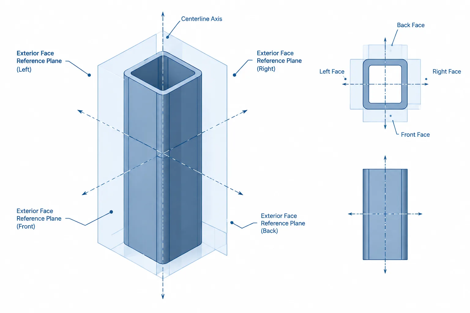
The longitudinal centerline of a straight HSS member runs through the geometric center of its cross section. In a square HSS, this axis is centered between each pair of opposite faces. In a rectangular HSS, it is still centered in both directions, although the distances from the centerline to the wide and narrow faces are different.
Plans commonly use centerlines because they provide stable layout references. Grid intersections, framing work points, and member axes can remain fixed even when a preliminary section is replaced with another size. This makes centerlines useful for structural analysis, early coordination, and global model control.
In a cross-sectional view, two perpendicular section centerlines may be shown:
- One centered between the left and right outside faces.
- One centered between the top and bottom outside faces.
The longitudinal member axis passes through their intersection. The orientation of a rectangular HSS determines which outside dimension extends in each project direction.
What Does Face of Steel Mean?
Face of steel, sometimes abbreviated in project-specific notation, means the exterior surface of the member. For square and rectangular HSS, the principal faces are generally treated as flat exterior planes for layout purposes. Actual corner geometry transitions through rounded regions rather than sharp intersections.
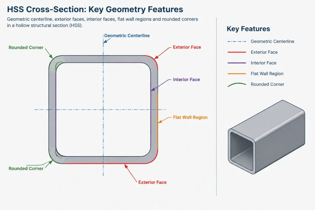
A face-of-steel reference may identify:
- The outside face aligned with an architectural wall or enclosure.
- The bearing or attachment surface for a plate.
- The near or far face used to dimension another member.
- The exterior limit used in clearance and clash checks.
- The surface from which a connection projection is measured.
Face-based dimensions become especially important when cladding, equipment, stairs, embeds, doors, or other construction must fit around the structural member.
Converting Between Centerline and Face Dimensions
For a square or rectangular HSS aligned with the drawing axes, the conceptual conversion is straightforward. The distance from a section centerline to an exterior flat face is one-half of the corresponding outside dimension.
If the member designation changes, that offset may also change. The centerline can remain fixed while the faces move inward or outward. This is why a shape substitution can affect clearance even when the framing grid and analytical member axis do not move.
Do not use wall thickness to calculate the centerline-to-exterior-face offset. Wall thickness is relevant when locating interior surfaces, but the exterior face is controlled by the overall outside dimension in that direction.
| Reference | What it controls | Typical use |
|---|---|---|
| Member centerline | Longitudinal axis and structural layout | Grids, framing plans, analysis models, work points |
| Section centerline | Center of the cross section in a selected direction | Offsets, orientation, symmetric connection layout |
| Exterior face | Physical outside surface | Clearance, cladding, plates, adjacent construction |
| Interior face | Inside surface of the HSS wall | Inserts, internal plates, access, fit checks |
| Tangent or flat region | Usable portion away from a rounded corner | Attachment placement and weld-access review |
Rectangular HSS Orientation Changes the Offset
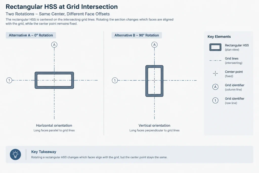
A rectangular HSS has different outside dimensions along its two principal section axes. Rotating the section changes which half-dimension applies in a project direction, even though the member centerline remains in the same location.
For example, a column may be centered on a grid intersection while its long side is oriented parallel to one grid direction. If the section is rotated, its center remains on the intersection, but all four face locations must be recalculated. That can alter wall clearances, beam setbacks, plate edges, and connection access.
Drawings should therefore communicate both member location and section orientation. A designation alone may identify the shape, but it does not always make the intended orientation unmistakable in every view.
Centerline-to-Centerline Framing Does Not Define the Connection
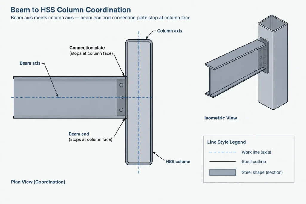
A beam centerline may terminate at an HSS column centerline in an analytical or schematic model. The physical beam, however, cannot simply occupy the same space as the column. Its detailed end location depends on the column face, connection type, erection clearance, plates, welds, bolts, and fabrication requirements.
This creates several related but distinct references:
- The analytical intersection of the beam and column axes.
- The column face where the connection is placed.
- The physical end of the beam or connecting plate.
- The work point used to define member geometry.
- The connection eccentricity between the load path and member axes.
A CAD model that shows only centerline intersections can appear coordinated while hiding an interference at the member faces. Detailed models and shop drawings must resolve the actual end geometry rather than relying solely on axis lines.
Face Alignment Can Move the Member Centerline
Not every HSS member is centered on a grid. Sometimes the controlling requirement is to hold one exterior face at a fixed location. This may occur at building perimeters, shaft walls, equipment clearances, or architecturally exposed framing.
When a fixed face controls, changing the HSS outside dimension moves the member centerline unless the controlling face is also allowed to move. This is the reverse of centerline-controlled framing:
- Centerline held: section faces move when the overall size changes.
- Face held: member centerline moves when the overall size changes.
The project team should identify which reference has priority. Otherwise, an apparently simple section change can create inconsistent structural, architectural, and fabrication models.
Inside Faces Require More Than a Simple Wall Offset
For initial checks along the middle of a flat wall, an interior surface may be approximated from the exterior geometry and the applicable wall information. Near HSS corners, however, the inside boundary curves through a corner region. It is not a sharp rectangle formed by offsetting four straight exterior faces.
This distinction matters for internal diaphragms, through-plates, sleeves, inserts, backing elements, and anything intended to fit inside the HSS. Published nominal data, design values, and measured product geometry serve different purposes. A fabricated insert should not be released solely from a simplified CAD opening without confirming the required fit, tolerances, corner geometry, weld seam implications, and fabrication procedure.
CAD Modeling Practices That Prevent Reference Errors
Model the section from a controlled insertion point
Use a consistent insertion convention, commonly the section centroid or geometric center for symmetric square and rectangular HSS. Record any intentional offset instead of manually dragging the member until it appears aligned.
Separate axes from physical geometry
Keep grids, member work lines, and section outlines on distinguishable layers or object categories. Users should be able to tell whether a dimension selects an axis, an exterior face, or a connection component.
Verify rectangular section rotation
Do not assume that the first outside dimension in a label automatically corresponds to a particular global direction. Confirm how the project’s modeling and detailing tools map section axes to plan orientation.
Dimension the controlling reference
If an exterior face must align with another object, dimension that face directly. If the member is centered on a grid, dimension the centerline. Avoid making readers infer a critical face location from an unrelated chain of dimensions.
Recheck faces after shape changes
When an HSS size or orientation changes, review more than the member label. Recheck face locations, clear openings, connection projections, edge conditions, architectural envelopes, and nearby systems.
A Practical Coordination Checklist
- Identify whether each member is controlled by its centerline, a work point, or a specific face.
- Confirm the wide and narrow directions of every rectangular HSS.
- Check that plan, elevation, section, and model views use the same orientation.
- Distinguish analytical axis intersections from physical member ends.
- Verify exterior clearances using the actual selected section geometry.
- Review internal-fit details using realistic corner and wall geometry.
- Revisit adjacent plates and connections after any section substitution.
- State intentional offsets clearly rather than relying on visual alignment.
- Avoid treating simplified CAD outlines as fabrication tolerances.
- Coordinate controlling references among structural, architectural, and fabrication documents.
Choosing the Right Reference
HSS centerlines are best suited to global framing layout, member axes, grids, and structural work points. Face-of-steel dimensions are best suited to physical interfaces, clearances, attachments, and architectural alignment. Interior-face references require additional attention to wall and corner geometry.
The key is not to choose one reference for every situation. It is to identify which reference controls each decision and show it clearly. When axes and physical surfaces are kept distinct, HSS layouts remain easier to revise, coordinate, detail, and fabricate.