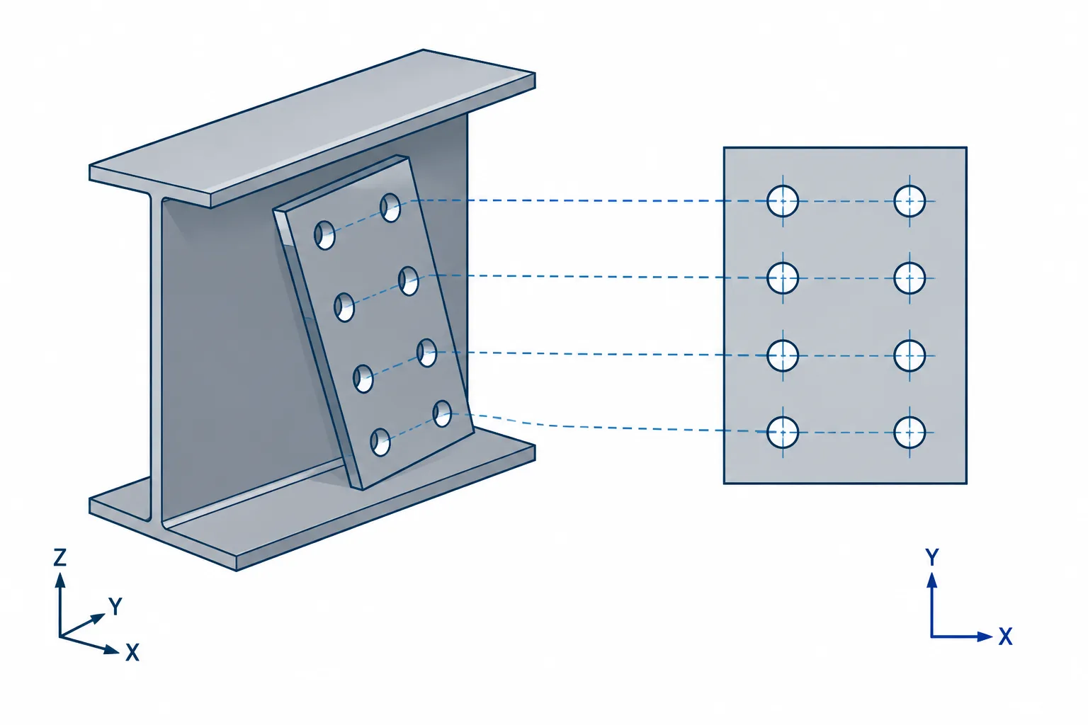
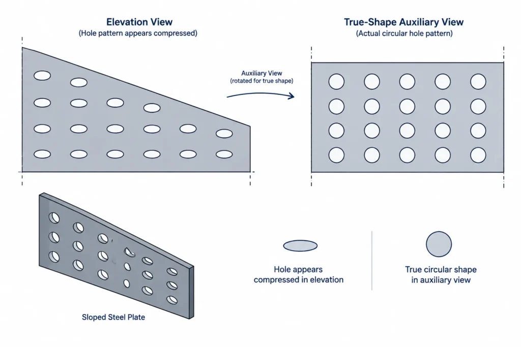
Hole layout becomes easy to misread when a steel plate is sloped, skewed, or shown in a view that is not perpendicular to its face. A bolt pattern that is regular on the actual plate may appear compressed, stretched, or irregular in plan or elevation. If those projected distances are mistaken for fabrication dimensions, the resulting holes may not align with the connecting material.
The central rule is straightforward: holes should normally be located in the plane of the material being fabricated. Plan and elevation views remain useful for locating the plate within the structure, but they do not necessarily show the true spacing of features on its surface. Drafters and modelers therefore need to distinguish plate-plane geometry from projected drawing geometry.
Why sloped and skewed plates create dimensioning problems
A plate is sloped when its face is inclined relative to a principal project plane. It is skewed when its edges, connection line, or supporting members are not square to the surrounding framing. A plate may be both sloped and skewed, as can occur at bracing connections, sloping beam connections, roof framing, stairs, trusses, and miscellaneous support assemblies.
When the plate face is not parallel to the drawing view, distances measured from that view are projections. Projection changes the apparent geometry:
- A true hole spacing can appear shorter in plan or elevation.
- A circular hole can appear elliptical in an oblique visual representation.
- Rows that are perpendicular on the plate may not appear perpendicular in the project view.
- Edge distances measured from projected linework may not equal the actual distances on the plate.
- A rectangular bolt pattern can appear as a parallelogram or other distorted shape.
This does not mean the project view is incorrect. It means that the view answers a different question. It shows how the plate relates to the structure, while a plate-normal view shows the geometry needed to fabricate the part.
True dimensions versus projected dimensions
A true dimension represents the actual distance measured along the plate surface or between features in the plate’s own coordinate system. A projected dimension represents the apparent distance after that geometry is viewed along a particular direction.
| Dimension type | What it describes | Typical use |
|---|---|---|
| True plate dimension | Actual distance in the plane of the plate | Hole layout, plate cutting, edge-distance checks, and fabrication |
| Plan projection | Horizontal projection onto the plan plane | Grid coordination, framing location, and overall plan layout |
| Elevation projection | Projection onto a vertical drawing plane | Levels, slopes, member relationships, and connection positioning |
| Section projection | Geometry viewed along a defined section direction | Clarifying offsets, plate inclination, and assembly relationships |
Projected dimensions are not inherently unsuitable. They can be necessary for locating work points, coordinating member positions, or establishing structural geometry. The problem occurs when the drawing does not identify which dimensions control fabrication.
Establish a local plate coordinate system
A reliable layout begins with a local coordinate system attached to the plate. One axis can follow a selected plate edge, member line, bend line, or other stable reference. A second in-plane axis is established perpendicular to the first within the plate face. The axis normal to the plate completes the local system and defines the direction for a true plate view.
The local origin should be a deliberate, repeatable point rather than an arbitrary model location. Common reference concepts include a plate corner, the intersection of centerlines, a member work point projected onto the plate, or a defined point on a connection line. The drawing should make the selected origin and directional references understandable.
Using local plate coordinates offers several advantages:
- Hole locations remain stable when the assembly is rotated in the global model.
- Distances correspond directly to fabrication geometry.
- Mirrored or handed parts are easier to identify.
- Coordinate-based checking becomes practical.
- Plate outlines and hole patterns can be compared in the same plane.
Global coordinates may still be needed for erection and model coordination. They should not replace local fabrication references unless the workflow explicitly converts and verifies them.
Use a view normal to the plate face
The clearest fabrication representation is generally a view looking perpendicular to the plate face. In this view, the plate outline, holes, slots, and cutouts appear in their true planar geometry. Parallel rows remain parallel, perpendicular lines remain perpendicular, and in-plane distances can be dimensioned without projection distortion.
A good plate-normal view should communicate:
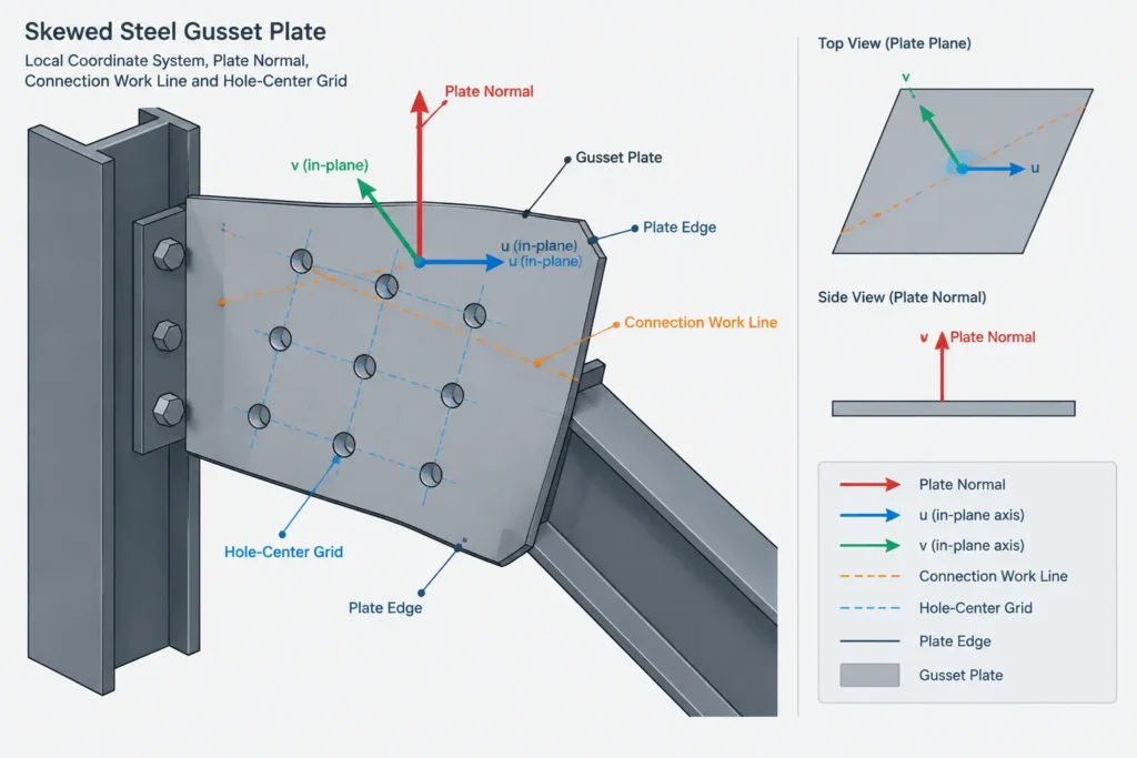
- The plate outline and relevant corner conditions.
- Hole centers, rows, and pattern orientation.
- References for gage, pitch, edge distance, and end distance where applicable.
- The relationship of holes to member centerlines or connection work lines.
- Any slots and the direction of their long axes.
- Part orientation, face identification, or handedness when ambiguity is possible.
An auxiliary view may be needed when a standard plan, elevation, or section cannot look directly at the plate face. In a model-based workflow, a part detail can serve the same purpose if it is generated and checked in the plate’s local plane.
Hole rows tied to different references
Not every hole pattern should be dimensioned from the plate edges. The proper reference depends on what controls the connection. Holes may be positioned relative to a supporting member centerline, a brace work line, a beam web, a flange face, a bend line, or the geometry of a mating plate.
For example, a plate outline may be trimmed or extended while the bolt line must remain fixed relative to the connected member. If the holes are dimensioned only from the changing plate edge, a revision to the plate size can unintentionally move the connection. Conversely, when edge distance is the controlling fabrication relationship, dimensioning from an unrelated global line can hide an important check.
The dimension scheme should preserve design intent. It should also avoid redundant dimension chains that can conflict after revisions. Reference dimensions may clarify projected or overall relationships, but controlling dimensions should be unmistakable.
CAD workflow for a dependable layout
Model the plate in its actual plane
Create or verify the plate as planar geometry with a known face normal. Do not construct the hole pattern by visually offsetting circles in a perspective or oblique view. Confirm that hole centers lie on the intended plate plane and pass through the material in the correct direction.
Define the controlling references
Identify the connection work line, member centerline, plate edge, or local origin that controls each portion of the layout. This should happen before dimensions are placed. A dimensioned drawing cannot correct a model whose reference logic is unclear.
Generate a true-shape view
Orient a detail view normal to the plate face or flatten the plate geometry into a validated local view. Check that the transformation preserves in-plane distances and does not introduce scaling.
Dimension in local directions
Place dimensions parallel to the local plate axes or directly between relevant hole centers and references. Avoid measuring from a screen orientation that only resembles the desired direction.
Cross-check the assembly
Return to the assembly model and verify that the holes align with the mating component. A correct-looking part detail can still be wrong if the plate or connected member was modeled with an incorrect rotation, offset, or face selection.
Common errors to watch for
- Dimensioning from plan alone: The plan may show only a shortened projection of the actual spacing.
- Using apparent plate edges: An edge shown obliquely may not provide a true in-plane offset.
- Flattening along the wrong axis: An incorrect transformation can preserve appearance while changing geometry.
- Mixing coordinate systems: Some holes may be located globally while others are defined from local plate references.
- Missing handedness: A mirrored plate can have correct spacing but place an asymmetric pattern on the wrong side.
- Ignoring slot orientation: Slot length and direction must be represented in the plate plane, not inferred from a distorted view.
- Trusting rounded display dimensions: Model coordinates and drawing dimensions should be checked for consistency rather than judged only by displayed rounding.
A practical checking sequence
Before releasing a sloped or skewed plate detail, review it in a consistent order:
- Confirm the plate face and local normal direction.
- Identify the origin and controlling in-plane axes.
- Verify the plate outline in a true-shape view.
- Check hole-center coordinates or dimension chains.
- Review edge and end relationships in the plate plane.
- Confirm alignment with holes in mating material.
- Check the pattern for rotation, mirroring, and handedness.
- Compare the part detail with plan, elevation, and assembly views.
- Verify that fabrication dimensions are distinguished from reference projections.
Clear drawings separate fabrication geometry from project geometry
Sloped and skewed plates are not difficult because their holes follow different geometric rules. They are difficult because several valid views show different projections of the same part. A clear detailing workflow separates the geometry used to locate the assembly in the structure from the true geometry used to fabricate the plate.
By establishing local plate axes, using a view normal to the plate face, identifying controlling references, and checking the mating components, drafters can prevent projection errors without over-dimensioning the drawing. Final layouts, hole types, clearances, and connection requirements must still be verified against the project documents and the responsible design information.