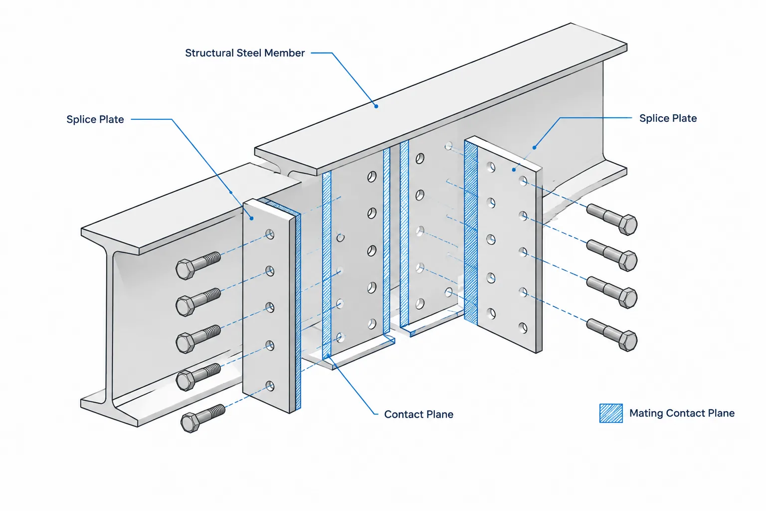
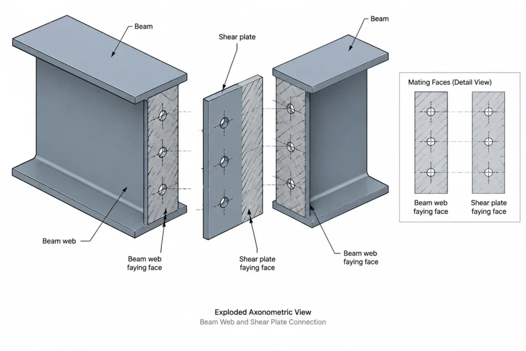
A faying surface is the portion of a steel part that contacts another part within an assembled joint. In a bolted connection, this may be the interface between a beam web and a shear plate, between splice plates and a member, or between the legs of connected angles and the supporting steel. Although the term describes a physical contact plane, its detailing significance depends on how the connection is designed and specified.
Faying surfaces are easy to overlook because they are usually hidden after assembly. A drawing may clearly show the bolts, holes, plates, and welds while leaving the actual contact interfaces implicit. That can create uncertainty about surface preparation, coating limits, masking, touch-up work, and which faces must remain free of contaminants. Good detailing identifies the relevant interfaces without assigning requirements that have not been established by the engineer or project specification.
What counts as a faying surface?
Not every face of a connected part is a faying surface. The term applies specifically where two components bear against one another in the assembled joint. A splice plate, for example, may have an inner face that contacts the member and an outer face under bolt heads or washers. The inner face is a faying surface; the exposed outer face generally is not part of that contact interface.
A connection can contain several separate faying surfaces. A double-sided web splice has interfaces on both sides of the web. A built-up assembly may include contact planes between plies as well as exposed faces under bolt components. Each interface should be considered independently because coating limits, assembly sequence, and access may differ.
| Connection condition | Typical contact interface | Detailing question |
|---|---|---|
| Beam web with shear plate | Beam web face against plate face | Does either contact face require special preparation or coating control? |
| Flange splice | Splice plate against flange surface | Are all inner plate faces treated consistently? |
| Web splice with plates on both sides | Each splice plate against the web | Are both interfaces identified, including the far side? |
| Bolted angle connection | Connected angle leg against supporting or supported member | Is the contact leg clear from the views and part orientation? |
| Multi-ply joint | Every interface between adjacent plies | Have hidden interior planes been included in the preparation scope? |
Faying surfaces and connection behavior
Bolted joints do not all rely on the contact surfaces in the same way. Some joints transfer force through bolt bearing against the sides of holes after relative movement occurs. Other joints are designed so that resistance to slip at the contact planes is a defined part of the connection behavior. The governing design documents determine the connection category and the required surface condition.
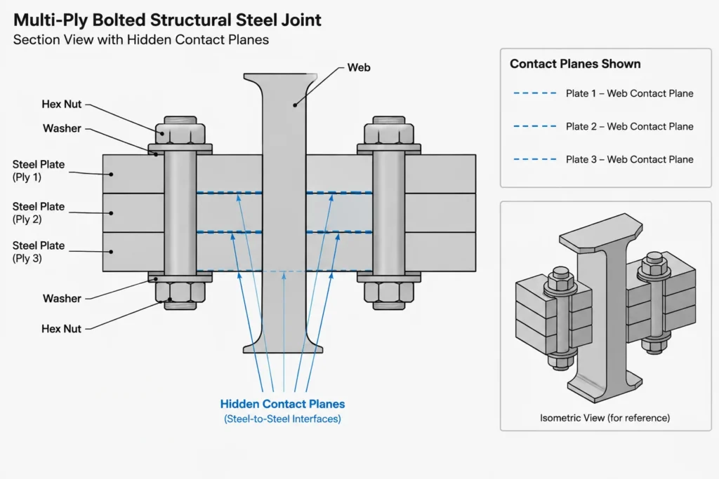
This distinction matters because a tightly assembled or pretensioned joint should not automatically be labeled as slip-critical. Bolt installation condition, hole type, load direction, and faying-surface treatment are related coordination issues, but one feature alone does not establish the complete design intent. Drafters and fabricators should use the terminology shown in the contract documents or confirmed by the responsible engineer rather than infer it from a typical detail.
Likewise, the phrase “clean steel” is not a complete surface-preparation instruction. It does not define an accepted coating, cleaning method, surface profile, or treatment boundary. When performance depends on the interface, the project specification and connection design must provide the controlling criteria.
Coatings, primers, and masking limits
Coating coordination is one of the most practical reasons to identify structural steel faying surfaces. A general note may require shop primer or another protective system on steelwork, while selected contact areas may need a different treatment. If the drawings do not distinguish these areas, the shop may be forced to interpret whether plates are coated before assembly, masked, prepared after fit-up, or left untreated.
The detailer should not assume that every faying surface must be bare. Some project-approved systems may be permitted at particular connection interfaces, while other joints may require a specified prepared condition. The correct treatment depends on the connection design and governing project requirements.
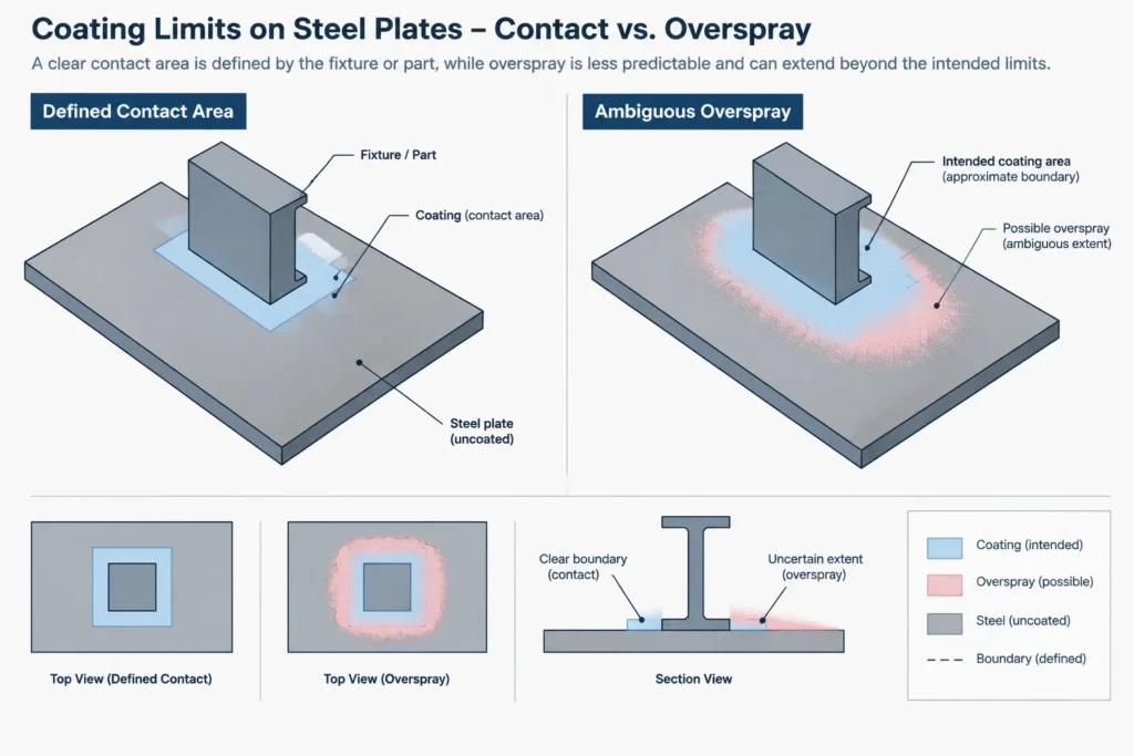
When masking or coating exclusion is required, the boundary must be buildable. A note such as “no paint at connection” can be ambiguous because “connection” might mean the entire plate, only the bolt group, or the actual overlap area. A more coordinated detail identifies the relevant face and defines the limit using recognizable part edges, match lines, or controlled dimensions supplied by the project requirements.
Questions to resolve before issuing drawings
- Which exact faces touch after the connection is assembled?
- Is the joint behavior dependent on slip resistance at those interfaces?
- What preparation or coating system is specified for each contact plane?
- Does the treatment apply to the full overlap or only a defined region?
- Must the shop mask an area before coating?
- Will field assembly expose untreated steel that requires later protection?
- Are both near-side and far-side interfaces covered by the notes?
Showing faying surfaces on steel drawings
A connection elevation often cannot communicate surface treatment by itself because the contact plane is viewed edge-on or is hidden behind another part. Sections, exploded diagrams, or face-specific part details are usually clearer. The objective is not to fill the drawing with hatch patterns, but to make the treatment scope unambiguous.
Useful drawing methods include a labeled leader to the applicable face, a section through the ply stack, or a part view showing the prepared region before assembly. If a boundary must be controlled, it should be tied to stable geometry rather than shown as a freehand patch. Notes should distinguish “this face,” “opposite face,” “both faces,” and “contact face” where those phrases could otherwise be confused.
Part orientation is especially important for plates that appear symmetric in outline but have face-specific preparation. If only one face receives a special treatment, the shop drawing and part mark must preserve that identity through cutting, coating, and assembly. Adding an orientation mark or assembly-side label may be appropriate, provided it follows the fabricator’s established marking workflow.
Common coordination failures
Applying a general paint note without checking the joint
A project-wide finish note can conflict with a connection-specific contact requirement. The connection detail, coating specification, and shop notes should be reviewed together. Silently applying the general note to every face can conceal an important exception.
Marking the plate but not the mating member
A contact interface has two sides. Calling out preparation on a splice plate while ignoring the flange, web, angle, or gusset against it leaves half of the condition undefined. Detailers should trace each interface as a pair of mating faces.
Using one note for multiple connection types
A standard note may be appropriate only for certain joints. If it is placed on a sheet containing several connection categories, its scope should be clear. Broad language can unintentionally assign special preparation to unrelated bearing-type joints or omit it from less obvious interior plies.
Ignoring fabrication and erection sequence
Some surfaces become inaccessible after shop welding or preassembly. Others remain exposed until field bolting. Preparation, inspection, coating, shipping protection, and field touch-up must fit the actual sequence. A technically correct face callout can still be impractical if it is issued without considering when the face can be reached.
A practical CAD and detailing workflow
- Build the ply stack. Identify every connected component in order, including webs, flanges, plates, angles, fillers, and shims.
- Trace the contact planes. Mark each place where adjacent plies meet. Do not rely only on the visible side of the main elevation.
- Confirm design intent. Check whether the documents define bearing behavior, slip resistance, bolt installation, hole conditions, or special surface treatment.
- Coordinate finishes. Compare connection notes with primer, galvanizing, fire-protection, architectural finish, and field touch-up requirements.
- Select a clear view. Use a section, face view, or exploded diagram if the contact area cannot be identified in the main connection view.
- Define the scope. State which face and which region are affected, using controlled geometry when a limit is required.
- Check mating parts. Verify that both sides of every relevant interface carry compatible instructions.
- Review the sequence. Confirm that the specified surfaces can be prepared, inspected, protected, and assembled in the intended order.
Use connection intent, not visual assumptions
Faying surfaces are physical features, but their required treatment cannot be determined from geometry alone. Two connections that look similar in CAD may have different design behavior, coating requirements, or assembly procedures. Conversely, a multi-ply joint may contain important hidden interfaces that are barely visible on the drawing.
The most reliable detailing approach is to map the contact planes, confirm the connection intent, and coordinate each mating face with the project finish requirements. Clear face identification and practical treatment boundaries help the engineer, detailer, fabricator, coater, and erector work from the same definition of the joint.