Category: How to
-
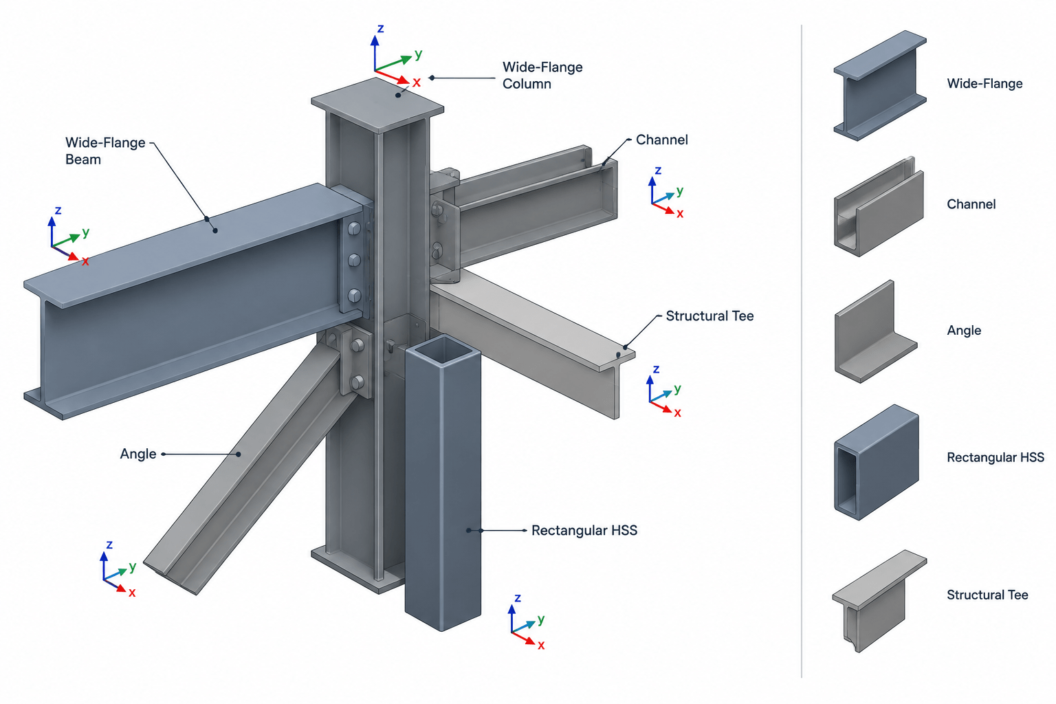
Steel Member Orientation in Plans, Elevations, Sections, and CAD Models
Learn how roll, slope, skew, local axes, and section rotation define steel member orientation in drawings and CAD models.
Written by
-
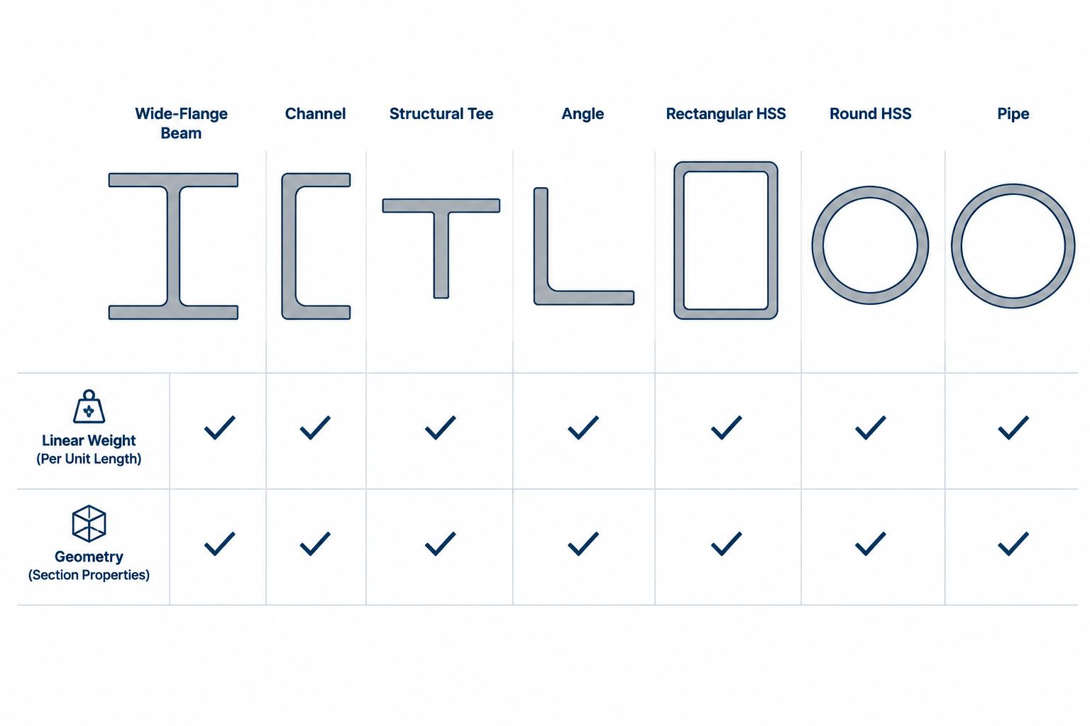
Reading Steel Shape Designations: Where Weight per Foot Appears—and Where It Does Not
Learn which structural steel designations include nominal weight per foot, which describe geometry instead, and how to estimate member weight correctly.
Written by
-
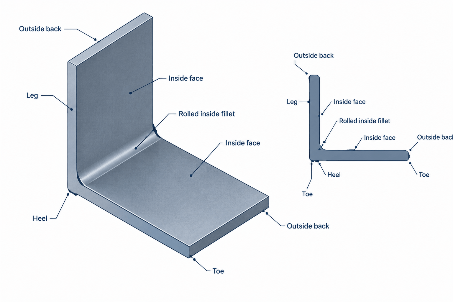
Steel Angle Terminology: Legs, Toes, Heel, Fillet, and Orientation
Learn structural steel angle terminology, including legs, toes, heel, backs, fillet, connected legs, orientation, and practical CAD detailing checks.
Written by
-
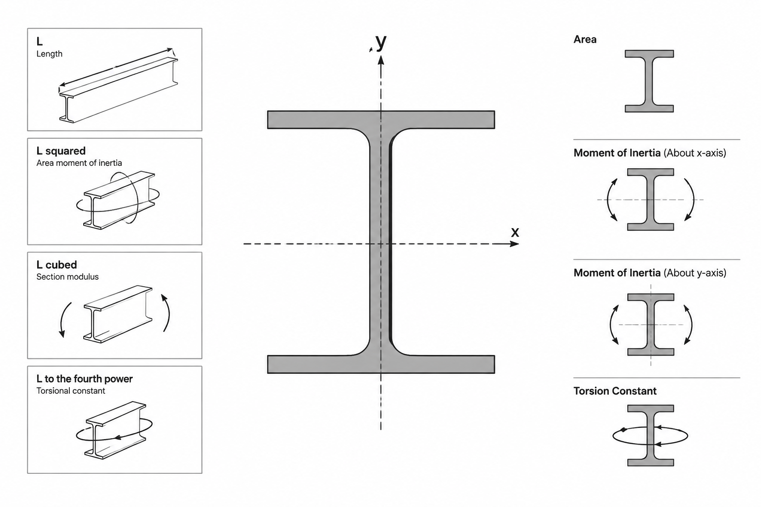
Steel Section Property Units: How to Read and Convert A, I, S, Z, r, J, and Cw
Learn the units used for steel section properties, why dimensional exponents matter, and how to convert shape data without common CAD and calculation errors.
Written by
-
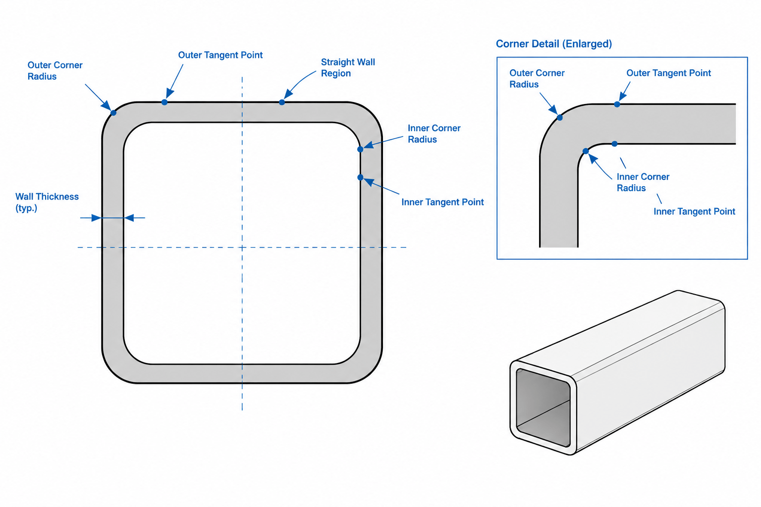
HSS Corner Radii and Flat Width: Practical Guidance for Detailing and CAD
Learn how HSS corner radii, flat widths, wall thickness, and outside dimensions affect steel detailing, connection fit-up, and CAD geometry.
Written by
-
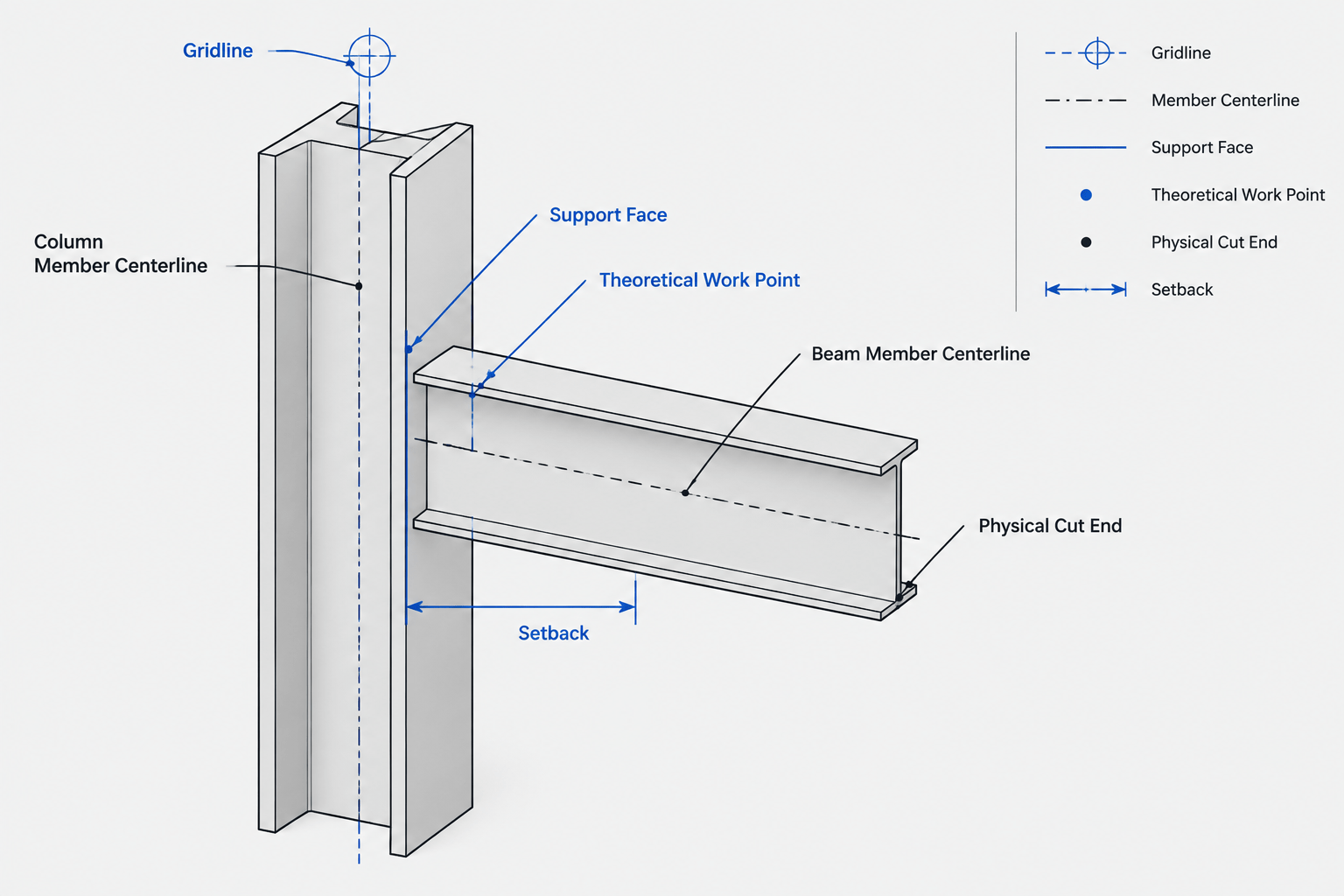
Work Points, Member Centerlines, and Setbacks in Structural Steel Detailing
Learn how work points, member centerlines, support faces, setbacks, and cut lines control structural steel detailing and CAD geometry.
Written by
-
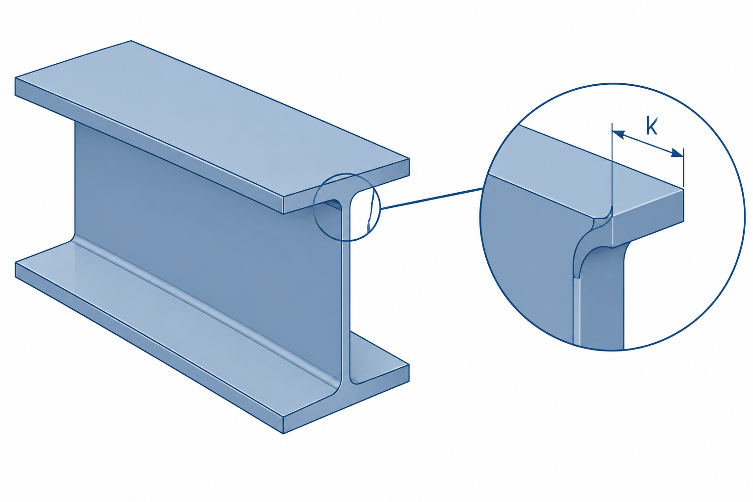
Steel Shape k Dimensions: Rolled Fillets, Detailing Clearance, and CAD Geometry
Learn what the steel shape k dimension represents and how rolled fillets affect connection detailing, clearances, stiffeners, and CAD outlines.
Written by
-
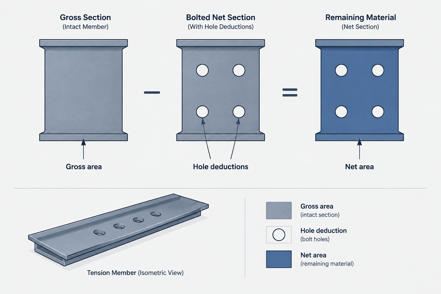
Gross Area vs. Net Area in Structural Steel Members
Learn how gross, net, and effective net area differ in steel members, why shape tables list gross area, and how holes and connection geometry affect calculations.
Written by
-
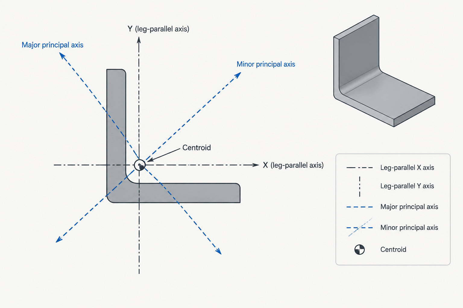
Principal Axes of Steel Angles: How to Read and Use Rotated Section Properties
Learn why steel angles have rotated principal axes, how principal properties differ from x-y values, and how to represent them correctly in CAD.
Written by
-
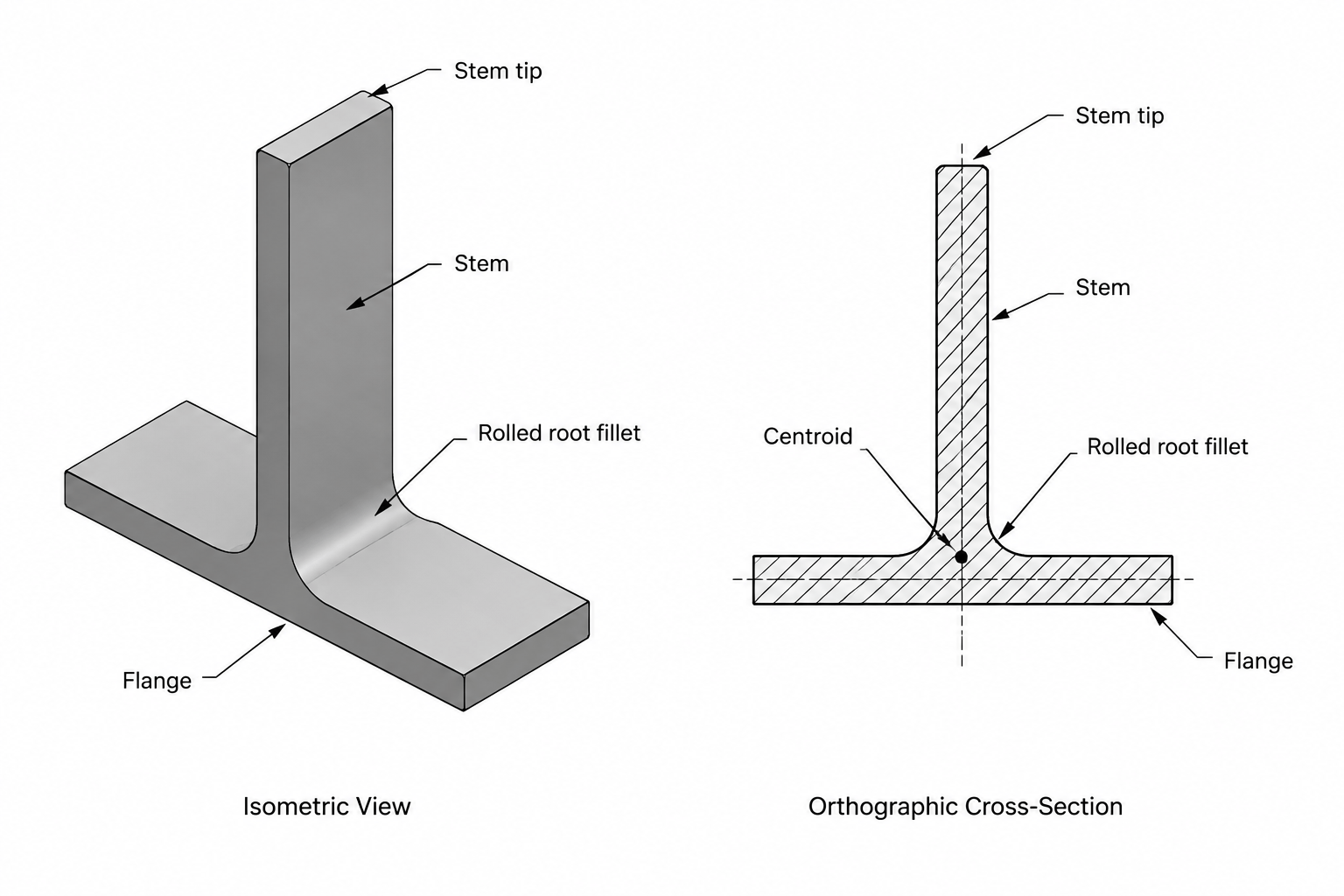
Structural Tee (WT) Shapes: Designations, Orientation, and Detailing Geometry
Learn how structural tee WT shapes are designated, oriented, detailed, and modeled, including centroid location, cut edges, fillets, and connection geometry.
Written by
-
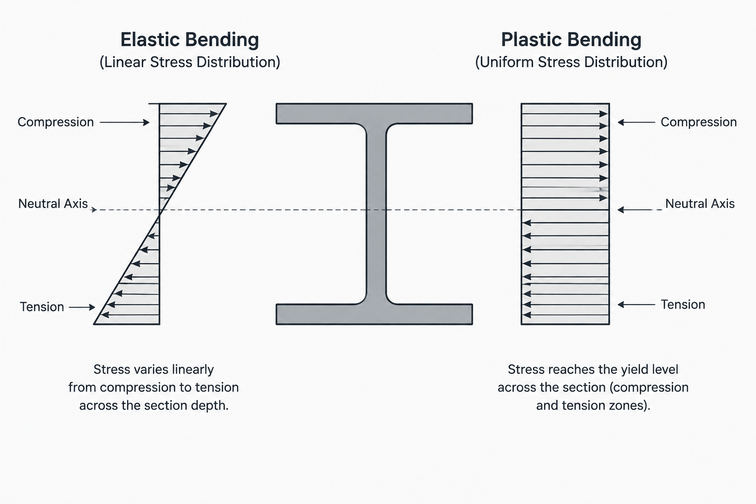
Elastic vs. Plastic Section Modulus: S and Z in Steel Shape Tables
Learn the difference between elastic section modulus S and plastic section modulus Z, how each relates to steel shape geometry, and how to read them in section tables.
Written by
-
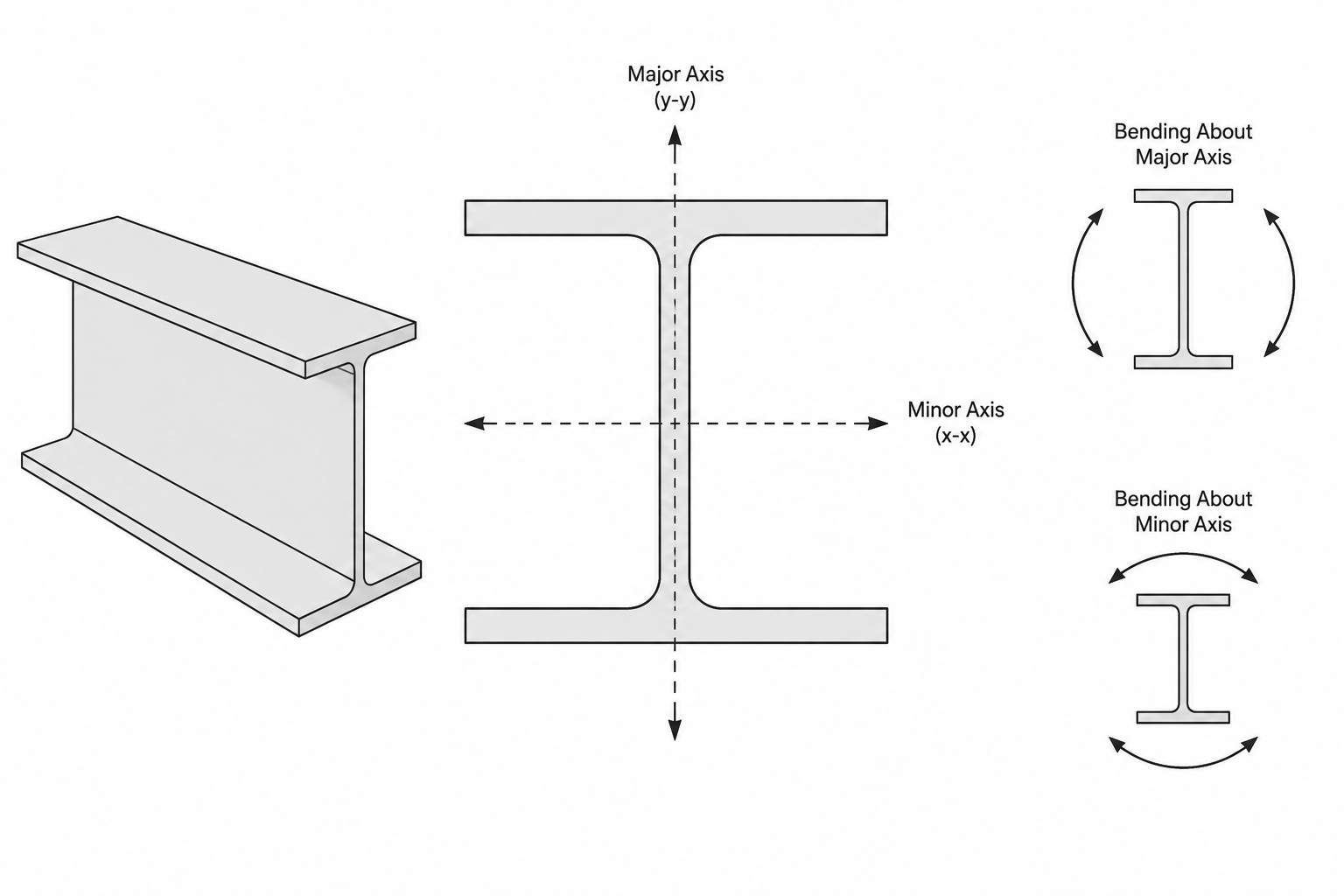
Strong Axis vs. Weak Axis in Structural Steel Sections
Learn how strong-axis and weak-axis bending relate to Ix, Iy, Sx, Sy, orientation, and detailing for W-shapes, channels, angles, tees, and HSS.
Written by